efzauner
-
Posts
719 -
Joined
-
Last visited
Content Type
Forums
Events
Gallery
Everything posted by efzauner
-
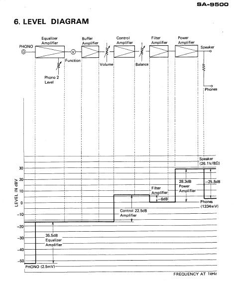
This is not that complicated. I think we have to be careful what is meant by gain. Attached is the gain chart for my SA9500 amp. Note the input sensitivity at Power Amp IN is specified as 1 Volts to provide rated output power of 85 watts into 8 ohms. This is shown on the chart as 1V = 0dBv at the input of the PA OdBv is referenced to 0V so in this case dBv= 20 Log (V PAin/0V) This gives a Vout of the PA of 26.1V that corresponds to 85W into 8ohms if you use P= V^2/R Gain is Vout/Vin. In dB this is 20xLog (Vout/Vin). = 20 Log (26.1/1) = 28.3 dB. So when I mean be careful of what is meant by gain is that if gain is Vout/Vin to provide maximum rated power you are not going to match your levels. What you need to do is find gain for all your amps for an equal Vout given identical Vin. For example, you want all your amplifiers to provide the same output voltage for a given input voltage. If amp A (for you HF section for example) provides 10v out for 1V in, it is a voltage gain of 20dB If amp B (for your LF section for example) provides 20V out for 1V in, it is a voltage gain of 26dB and you would have to use 6dB of attenuation. Note that Amp B provides 2x the voltage. You could use a simple voltage divider circuit using 2 10Kohm resiistors in series. Voltage gain in dB works for any impedance. That is why the chart uses voltage gain because input and output inpedances change in the circuit. If you do not have such a chart then you could determine gain yourself with an audio generator (your laptop or phone and an online audio generater!) and voltmeter If you use power gain, which is 10 x Log Pout/Pin you have to calculate power using voltages and resistance. In this example, without using any attenuation to equalize the amps: Amp A at 10V out into 8 ohms gives you 12.5 watts Amp B at 20V into 8 ohms gives you 50 watts. the power difference between amp B and amp A is 10 x Log 50/12.5 = 6 dB the same as the voltage gain! now all of this assumes equal impedance and sensitivity drivers which is rarely the case! You would have to take both into account and back calculate the PA voltage into the drivers to provide same SPL, and then provide the right attenuation at the input of the PA to equalize them. Have fun! E

-
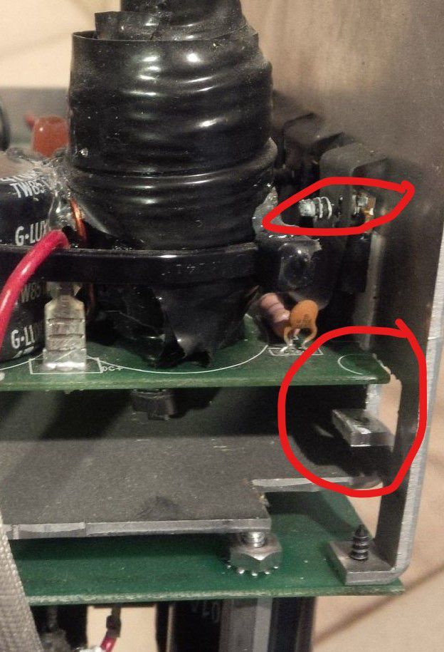
I posted my repair success on my RSW15 on another post. But just some funny things you see on previous repair attempts When finally re assembling the indigo bash board I was missing 6 screws. I just assumed after 2 years I had lost them. Then I took a closer look at the picture I took originally when I disassembled it. There where NO screws! The pcb is floating above the mounting tabs! The guy had put screws thru the TO220 mounting holes systematically shorting every power FET and Diode! LOL no wonder it didnt work! Egg on my face for not catching this originally... oops!
-
Measuring autotransformer values....
efzauner replied to Alexander's topic in Technical/Restorations
The models seem to be using inductors as a voltage divider elements and not as any transformer where the voltage out/in is a function of turns ratio. I believe you have been implying turns ratio into the inductance values. This link uses inductor K coupling factor to create autotransformer models. Some good info here! http://www.beigebag.com/case_tapped_inductor.htm As for phase shift... if you write the inductor model as jwL and use voltage divider math Vout/Vin = jwL2/(jwL1+jwL2) the jw cancels out so you do not have any phase change... This makes intuitive sense as well since if use 2 identical inductors the magnitude of the voltage phasors Vout has to be half of Vin. KVL would not work if the phases of Vin and Vout arent the same.. Am I making sense? E -
Correct way to wire crossover inductor?
efzauner replied to Robbie010's topic in Technical/Restorations
yep inductors in crossovers are used to attenuate higher frequencies... so what if there is a bit more resistance due to skin effect... even if so tiny to be irrelevant at frequencies where crossovers are used as in bass or mid/high cuttoff say maximum 5KHz.! -
I have a pair of K-1056-Ks available.. and I used a previously posted sheet to create a TS parameter driver file for WinISP. These would be to augment the low end of my Heresys for music listening, not for earth moving HT bass.. I have an SWR15 for that. I can play all day with Win ISD but would appreciate your feed back on qualitative sound for the following options. I have a 240wpc crown pa amp to drive these. Does anyone know what the Xmax of these are? Fiddling with the signal I get cone excursion of about 10mm with 100w signal at 35 and 60Hz on a vented design that mimics the KLF10 Box. Does this make sense? I want the box to be not much more than 50 liters as they will be used as base/risers for my Heresy's On the the main question I am thinking of the following options: 1: vented design but with lower F 2: Sealed design with 6db/octave shelf eq 3: Sealed design but adding about 30g of mass to the cone. This seems the simplest design has anyone ever tried this with any LF driver? The last option seems interesting. I could also just make a box with a vent, and play with vent size.. and even seal the vent... Even with a movable partition to change the volume!! to try different configs. thanks E
-
The RSW 15 has a high pass filter of 12dB/octave below 20Hz . So it would be 12 db down at 10hz and 24 db down at 5 Hz. Very odd that your 5 Hz signal is getting thru. PLUS there is power limiting also below 23Hz. Both of these should have protected the driver and PR from over excursion. Something else is going on here. How did the other 2 respond to 5 Hz? To 10 Hz? 20Hz? Just curious.. I should try it on my RSW15! As for the LPF frequency, how are you connecting the sub to your HT receiver? Normally you use the LFE out on your receiver connected to the RSW15 input and set it to LFE. That way the receiver sets the high pass/low pass for your main speakers (if they are set to small) and to your sub.
-
Sub Appears to come out of standby mode but no sound
efzauner replied to Scuzzi's topic in Subwoofers
Lets isolate some things here. First lets get the auto on circuit out of the way. Does it work at all in normal (not auto on) mode? If so, then there is something wrong in the auto circuitry If it shows same issues on both on and auto mode then could be an issue somewhere else with turn on delay etc. You would have get it repaired. E -
I suspect that it may have shown signs of overheating because of the short or just abuse. Maybe the owner thought that it was the only part that needed changing. Dunno.
-
-
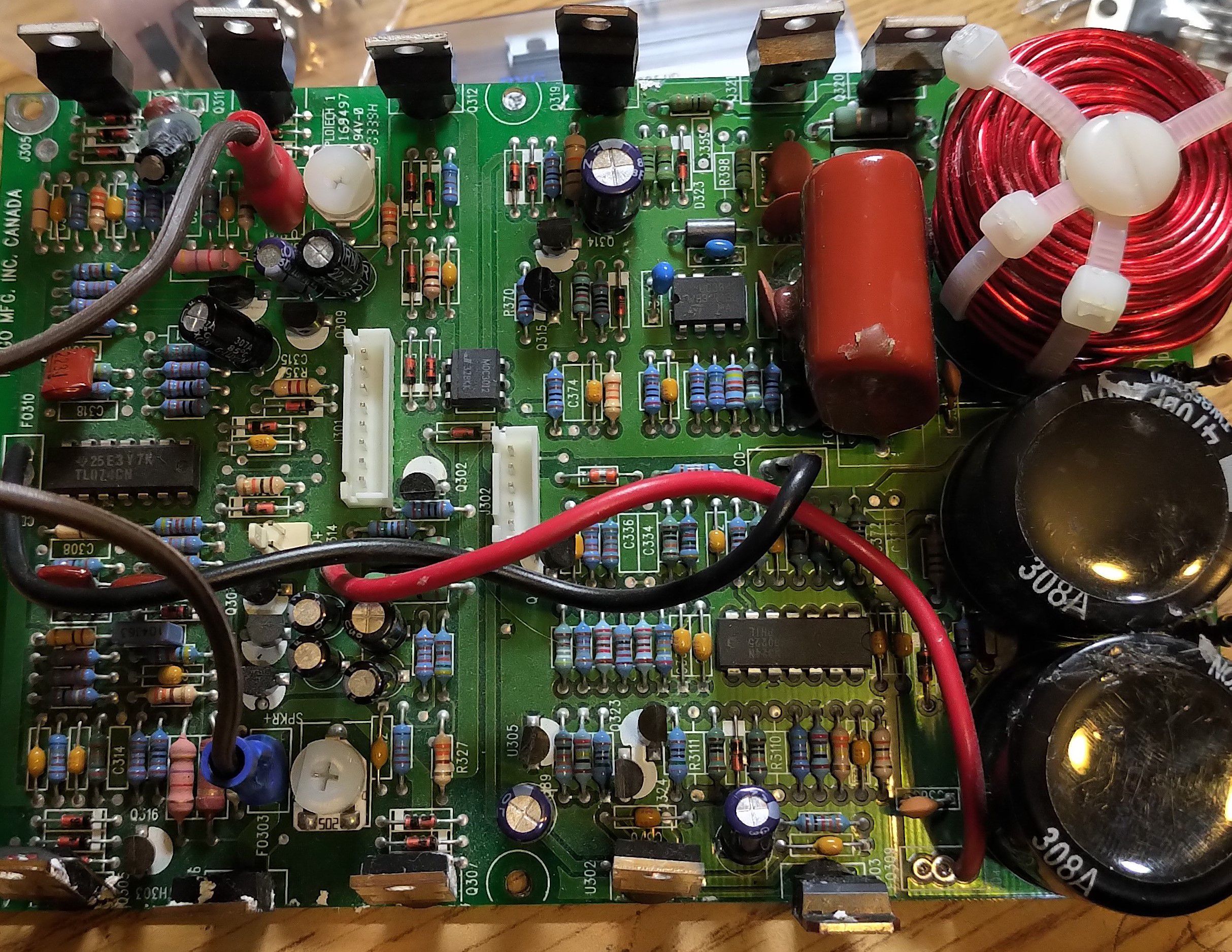
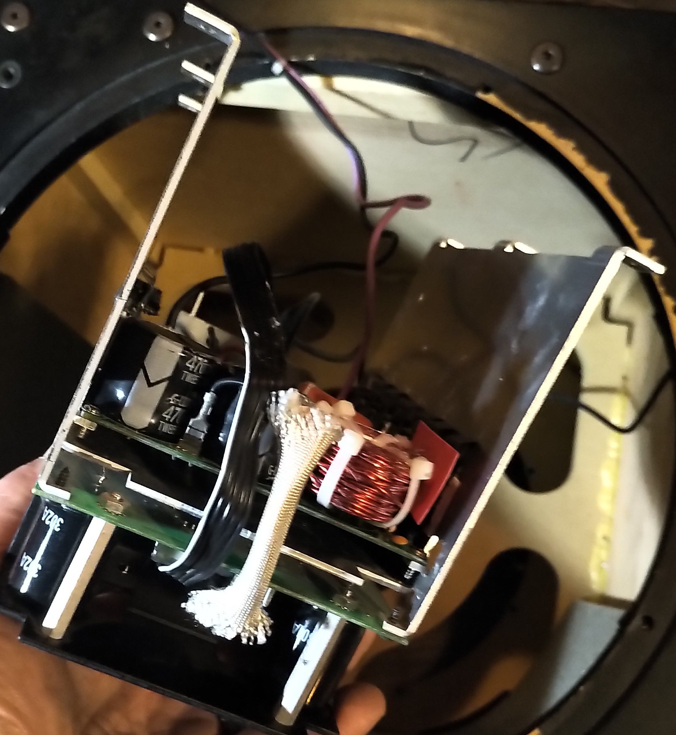
repaired bash amp
-
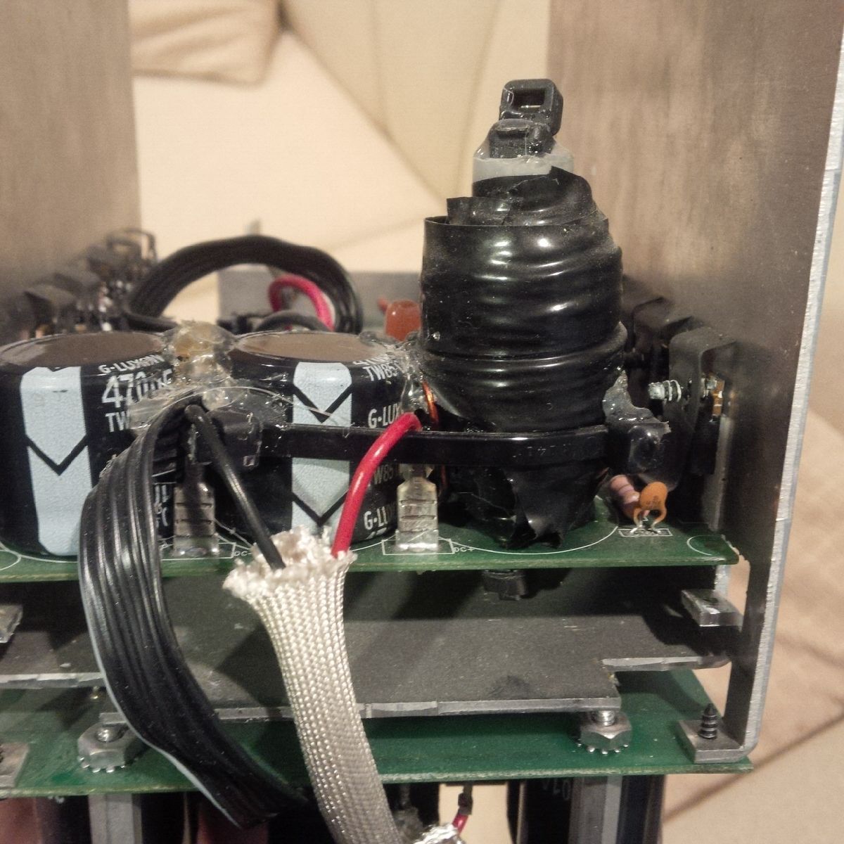
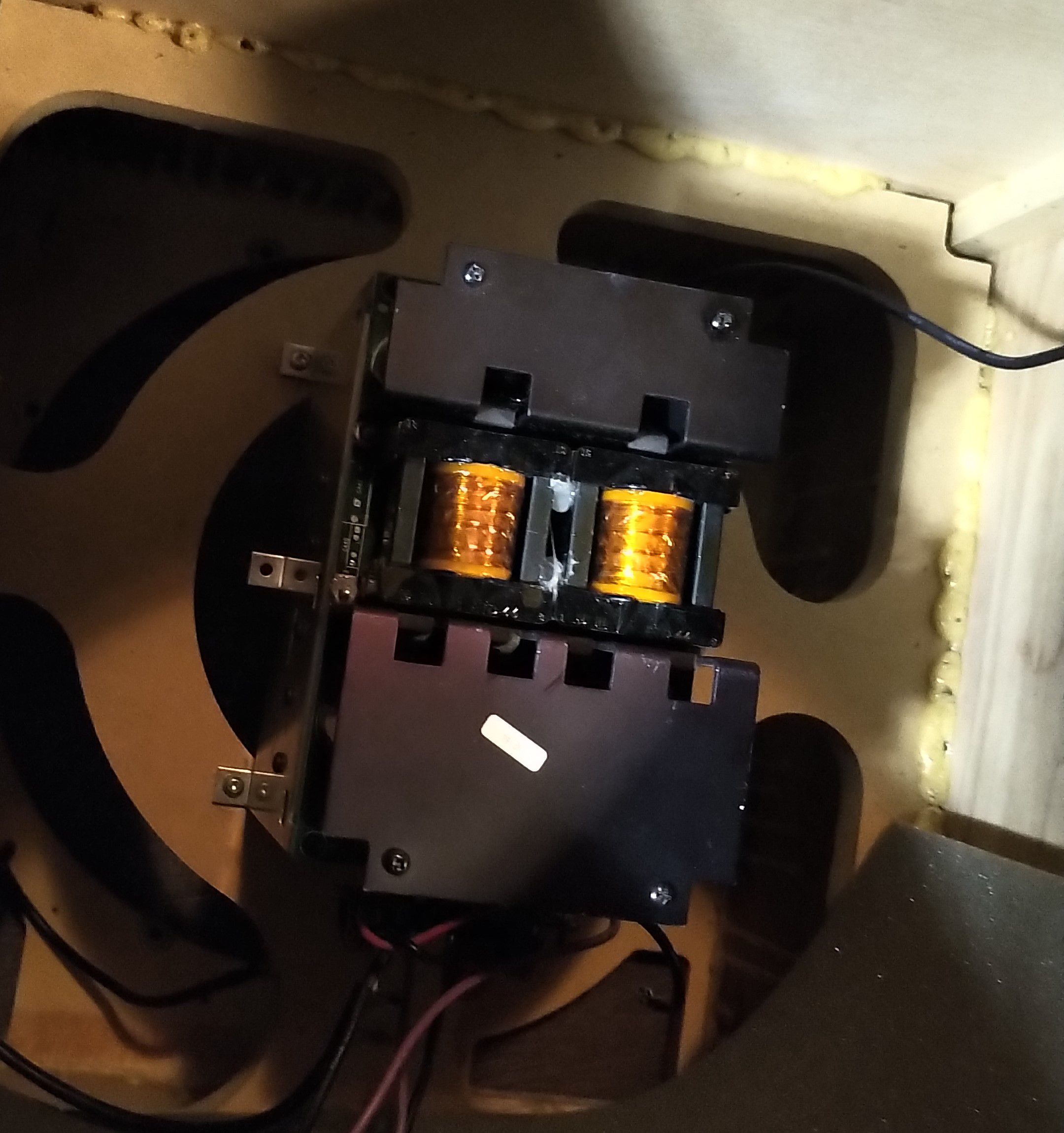
Bash amp assembly with previous home made inductor that I replaced.
-
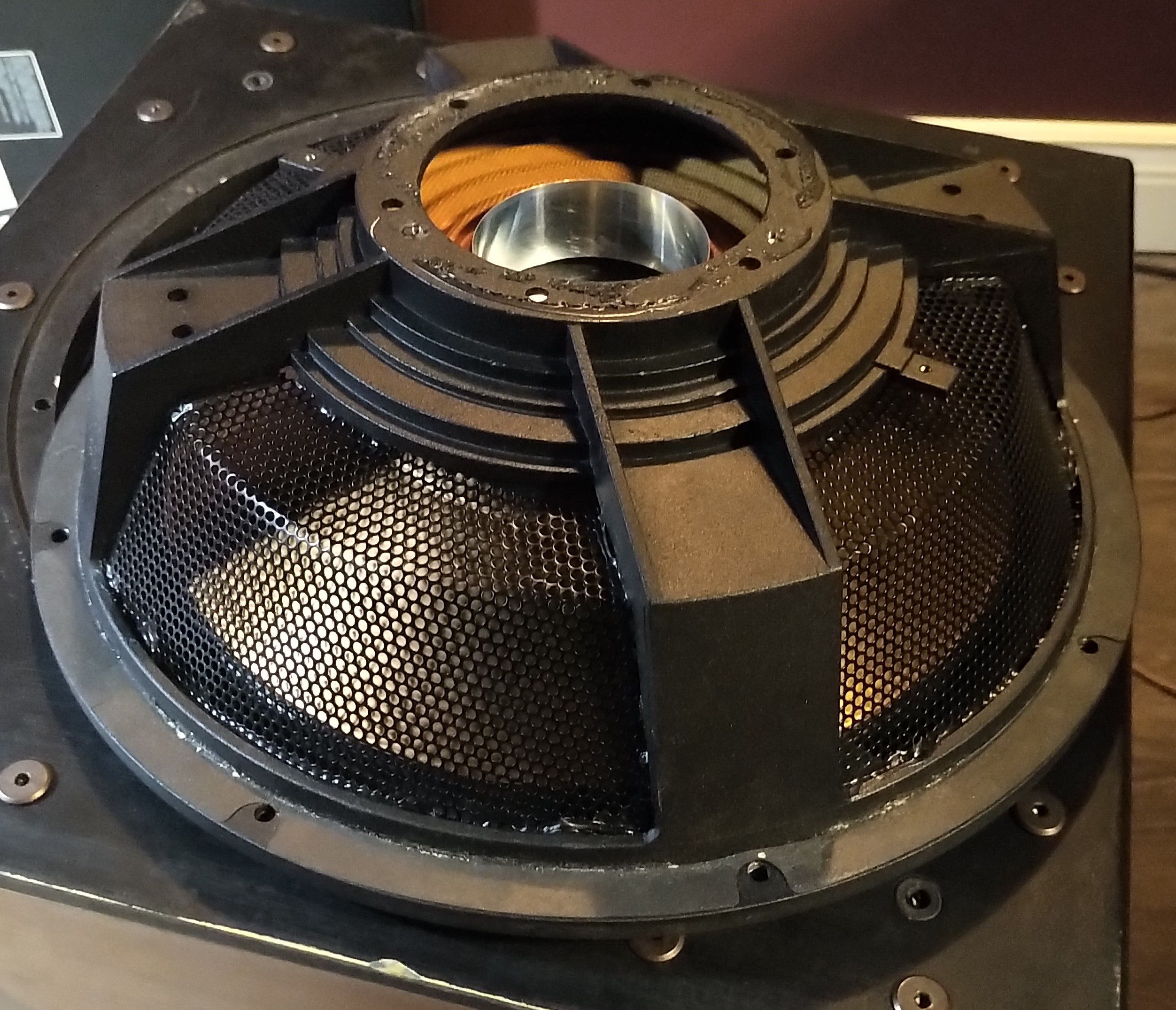
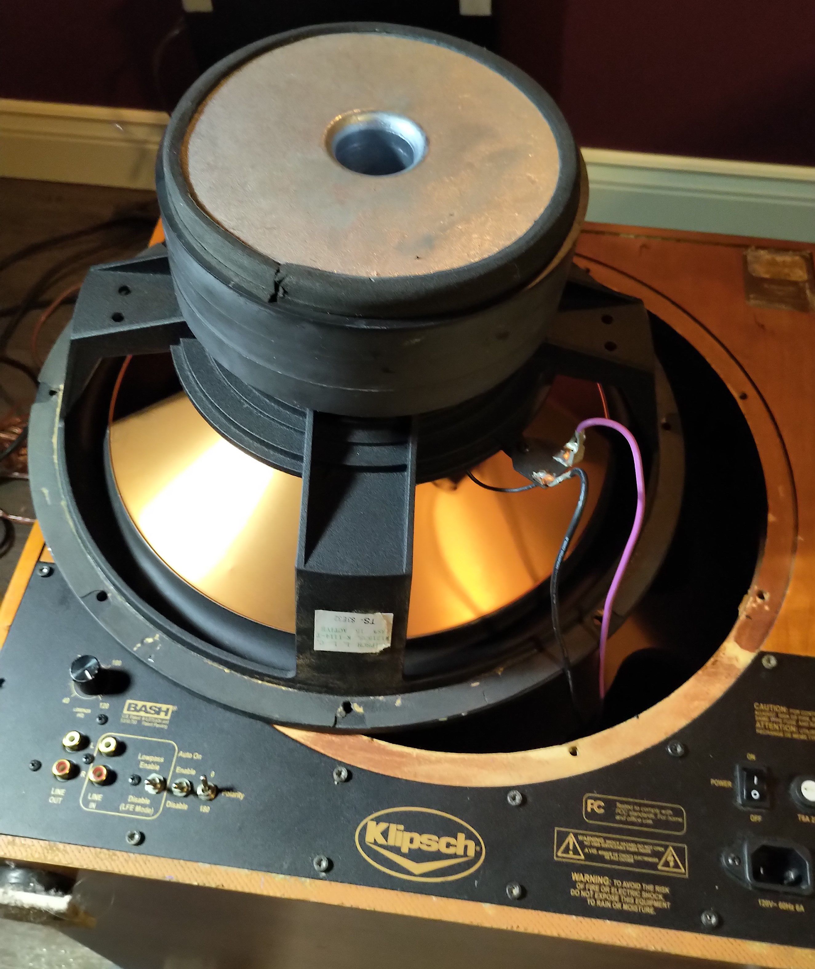
more pics of passive radiator removed to access amp. as well as repaired amp ready to install with new inductor.
-
Hello fans! Over 2 years ago I purchased a non functional SWR15 for $200 Canadian. The owner had attempted a woefully inadequate repair. An attempt was made to replace the main SMPS inductor L302 but no other electronic parts where replaced. Plus the cabinet was not in great shape as it seemed to have undergone some water damage or at least it was in a very damp basement for a while. Fixing the cabinet, re gluing etc was the easy part. I did not try to make it cosmetically pristine. Just working. It is in the corner of the HT room behind the sectional sofa so nobody sees it anyway. I removed the amp and face place electronics board and replaced it with a wood panel so I could connect speaker terminals and use it with an external amp... I began a repair 2 years ago but stopped. Finally got it done. I consider this a more advanced repair and I am not going to go into every details on repair basics. If you don't know how to check PS voltages, check for blown transistors, desolder and solder and mount transistors with ceramic insulator and heatsink compound I suggest you read up on that stuff. The amp is powered by +/- 85v and is in a bridge configuration that is floating. Not easy to connect a grounded scope probe to look at signals. I did not have a differential probe. In the end the repair was winding a new inductor and replacing almost all of the power semiconductors in the PS and PA board. Had it been some other circuitry this may have been more difficult to troubleshoot. Service manual was easily available from HiFi Engine but it was lacking info on the main switch mode power supply 150uH inductor L302 and had no bias adjustment info. Long searches led me to the JBL HTPS 400 and infinity-Intermezzo 1.2 and4-1t manuals. that had the identical Indigo electronics. Note that Indigo makes the entire kit including the feature board with all the LPF and protection circuits. The Infinity manual has some good blown fuse troubleshooting info also. These 2 manuals gave me the inductor value and bias adjustment. Note that its almost as if they keep things out on purpose. The Klipsch manual had no inductor value nor bias info and the JBL manuals lacked the envelope following SMPS schematic! The Infinity manual had both. The only differences are how the main PS board and SMPS Bash amp board are mechanically mounted. In the Klipsch it is 1 assembly on heat sink, on the others they are separate. After disassembly and putting it all on my test bench for testing. I had removed the control panel also so that I could use the power cord and on off switch as well as signal source as necessary. There are a number of circuits for thermal shutdown (with a thermistor on one of the PA mp Mosfets. This was originally thermal epoxied on to the TO222 transistor but I did not want to spend $50 for thermal epoxy so I glued the leads to the side of the case and used normal thermal paste between the thermistor body and transistor heat sink tab. ). Over current sensing. Clipping detection, Soft clipping, Auto on etc. so since I had no clue where everything was I decided to have the entire setup. I did not try to just power the PS and Bash board. It may work. So the main guts are on 2 boards mounted on a common heatsink that screws to the brace between the sub and passive radiator : A general Switch Mode power supply board that provides all DC levels to the various circuits as well as the main 170V to the Bash amp board. The Bash board has the envelope following buck mode switching power supply and the main amp in a bridge-H config similar to car audio amps. a single IRF640 N fet on each side and paralleled IRF9640 P channels on the other legs of the bridge. The envelope following Buck PS has 2 IRF640s and a power diode. First thing I noticed was what looked like a home made inductor.. Heads up! Plugged it all in and found that the bash amp was shorted. Removed that inductor and the short was removed and the mains where back up at 170V. First conclusion was that something after that inductor was shorted. Easy enough to test the power diode and all the power mosfets. That was all that required replacing. I wound my own inductor based on the 150uH from the JBL manual and double tested the value with my old HP impedance analyzer and in a resonant circuit with a known capacitor. And that was it! up and running again! see pics attached... the Klipsch manual is on Hifi Engine. I do not recall where I found the JBL and Infinity manuals. They are over 2Mb and don't fit here but send me a message with your email and I will be happy to email them.
-
So my RSW15 is up and running again with a bunch of Mosfet changes as well as winding a new L302. Many Fets shorted out including the power diode in the SMPS. That must have caused the original L302 to overheat causing the previous owner to try to wind his own (badly) without bothering to check for any other problems. Great buy at $200 Canadian and $20 in parts!
-
This is cool! Just what I need to make a pair of bass bins with the K-1056-K woofers I have! thanks!
-
never mind. answered already cant delete a post?
-
RSW 15 about the best sub Klipsch ever built. http://www.klipsch.com/rsw-15-subwoofer SW 15 best when it was built https://web.archive.org/web/20130308095335/http://www.klipsch.com/sw-15 just in case you where not aware of the klipsch web archive for older products. https://web.archive.org/web/20120121104208/http://www.klipsch.com/discontinued-speakers
-
and the JBL manual is too big so send me a PM and we can do it by regular email
-
here you go hfe_klipsch_rsw-15_service.pdf
-
I am reparing my RSW15 bash amp as we speak. replaced several blown/shorted Mosfets. I think I have it working again. I even had to wind my own L302 inductor. Have to get a thermistor before I can finish it as it was epoxied to a blown fet. One of the issues with these amps is that the the power amp is floating at +/-85 V rails and is a bridge connection You cannot clamp a scope probe ground to the speaker output. I can give you some pointers if you want. Note that the amp is the same as in JBL HTPS400 The JBL service manual is more complete. I can send them to you if you want. E
-
I have had a Dual 510 auto shut off since late 70s and has been in operation without any maintenance off and on since.! Enjoy!
-
cool project. I have a pair of KLF10 woofers for same. KLF 10 vs KLF 30 specs say KLF 10 has 32 -3db point. vs 36Hz for KLF 30.. Do you plan to use same box/port? This is good bass response but not exactly a sub woofer. wondering if you would want a high pass to cut power below resonance and uncontrolled woofer ?
-
bump includes the 2 ports also
-
Questions regarding having new enclosures built for my Heresys
efzauner replied to wuzzzer's topic in Technical/Restorations
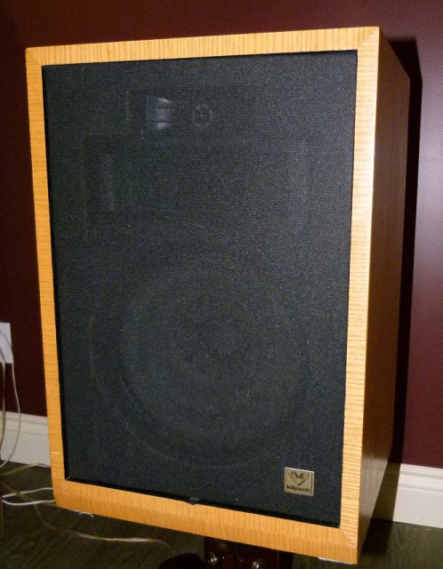
I have Heresies made by someone else over 15 years ago.. Same cabinet but braced inside and re veneered with front mounted tweet an mid.. here is a pic.. they are very pretty and sound amazing...
-
Very pretty. I am looking at doing similar also with Heresy parts. perhaps only the standard 12 inch woofer. What Focal woofers did you use? 8inch? 10 inch? What crossover? I gather you used std Heresy Xover for the mid/high but what for the woofers? Their impedances , efficiencies? etc? You say timber matched, sure for the mids/highs but so much of our hearing is in the under 700Hz range where the woofers operate. I have 2 Eminence Alpha 8A to use. but their impedance curves are very far from the K22 that I fear using the same LF circuit./inductor. thanks