Arkytype
-
Posts
448 -
Joined
-
Last visited
Content Type
Forums
Events
Gallery
Everything posted by Arkytype
-
Here's a handy calculator (and very useful web site) to see how humidity and temperature affects the speed of sound. Plug in different values of Temperature or Relative Humidity and you'll see that changes in temperature affects the speed of sound much more than humidity changes. http://www.sengpielaudio.com/calculator-airpressure.htm Lee
-
Coytee, You have a nice Hewlett Packard 400EL which is a wide band (10Hz-10MHz) and wide range (1mV to 300V) AC voltmeter. The "L" in the 400EL model means that the meter has a linear dB scale on top and a logarithmic voltage scale underneath. Most analog AC voltmeters have a linear voltage scale above the logarithmic dB scale making it harder to see small dB changes. You don’t need a calibrated eyeball to see changes as small as 0.05 dB on your 400EL meter scale! The first step in troubleshooting your problem is to turn both volume controls of your BX-3 to the same “time” setting; e.g. ten o’clock. Now play music and note which La Scala is louder, left or right. For sake of illustration, let’s say the right La Scala is louder than the left. Stop the music and at the rear of the BX-3 swap the left and right channel speaker wires. Again, play music and note which La Scala is louder. If the right La Scala is still louder than the left, there’s something wrong with the left La Scala. If the left La Scala is now louder than the right, then your problem is with the BX-3 or the AVR. Since the BX-3 is a four channel amplifier, you could repeat the above troubleshooting steps using the left and right front amplifier channels. That way you can double check if you have a La Scala or a BX-3/AVR problem. If you determine one of your La Scalas is the problem, PM me and I’ll send you a comprehensive troubleshooting guide which includes using your HP 400EL to determine if you have a crossover network or driver problem. Lee
-
Tapajeurs, et al, There are several caveats to consider when attempting to accurately measure the ambient noise level in a listening room (or any acoustic space for that matter). Let’s begin by using terminology that helps us define exactly what we are measuring. You wrote,“I have a reading of 35db is it good?” A more accurate statement would be, “I have measured the sound pressure level in my listening room and it is 35 dB.” Sound Pressure Level (SPL) is based on an internationally-recognized reference sound pressure of 20 micro Pascals (written 20uPa) and corresponds to a SPL of 0 dB @ 1 kHz. This reference quantity is defined as the threshold of human hearing or auditory threshold. Until your SPL meter has been calibrated with a known SPL, the value you read may or may not be close to the actual sound pressure level in your listening room. OK, you say, let’s build a SPL calibrator that puts out 0 dB SPL, calibrate our meter and we’ll be good to go! Well, we could theoretically build a calibrator that would generate 0 dB SPL at the microphone diaphragm. But that low SPL would be swamped by the self-noise of the microphone capsule and/or by the microphone preamplifier. Instead, we use calibrators that generate higher SPL levels. 94 dB SPL @ 1kHz is a popular calibration level which happens to correspond to 1.0 Pascals and is a sound pressure increase of over 50,000 from our 0 dB reference! Note that you will need a SPL calibrator that allows your measuring microphone to snugly fit into the calibrator otherwise you will get an erroneous reading. Most professional calibrators have a ½” diameter opening. When we measure acoustic spaces to determine say, how quiet a classroom is or the loudness of a ventilation system, we should use a “weighted” SPL reading. An “A” weighting filter corresponds to how humans perceive low to moderate SPLs. That is, the bass and treble frequencies are rolled off below and above 1 kHz. So, if your SPL meter reads 35 dB SPL un-weighted, it might read 25 dB SPL with the A-weighting filter turned on and 25 dBA would be a quiet space! The ER CHEN F-1350 Sound Level Meter you referenced is similar to the several dozen under-fifty dollar SPL meters for sale on the web. Notice that the microphone capsule has a frequency response from 31.5Hz to 8 kHz. Hope you don’t plan to measure your tweeter’s frequency response! Also, we don't know the inherent noise level of the microphone capsule+electronics which will affect the low end of the 30 dB spec. The rated upper limit of 130 dB is probably at 5-10% distortion. Save your money and get something like the Dayton Audio OmniMic V2 computer based measurement system which comes with calibration files and room measurement software. Yeah, it’s $300.00, but the next level of expenditure would be well over $2,000 for something used from Bruel & Kjaer, Larson-Davis or General Radio (GenRad). There are several informative web sites that will give you some insight into acoustic measurements and the math involved. One of my favorite is www.sengpielaudio.com. Here’s a link to "Sound pressure, Sound Intensity and their Levels". http://www.sengpielaudio.com/calculator-soundvalues.htm For you information gluttons, here’s his extensive website index: http://www.sengpielaudio.com/Calculations03.htm Regards, Lee
-
Ok, here's my entry. The guy in the plaid pants and sideburns is Bob Moers who would drive us in his BMW at warp nine down the back roads of Hope. Lee

-
John, et al, Yep, they are right where you said they were! An elegant solution to a difficult problem. Raise your hand if you would have connected the upper and lower sinuses with a PVC pipe. Here's a link to the building of the Plexiglass Klipschorn. Maybe we should have a photo caption contest. Lee https://www.flickr.com/photos/klipsch_audio/sets/72157634899990129/
-
John, The PWK quote from THE "MAXIMUM" CORNER HORN paper where he states, "....and a means of coupling in the top and bottom sinuses,..." is curious. The modern-day Klipschorns do not utilize the volume in the top and bottom sinuses. Unless my Klipschorns purchased new in 1979 are an anomaly, there is no connecting passageway from the top and bottom sinuses to the rear air chamber. In his paper Improved Low Frequency Horn (JASA, Vol. 14, No. 3 179-182, January, 1941) PWK wrote that he did increase the volume of the rear chamber by, ...opening up the otherwise dead air spaces in the front of the cabinet lying on either side of the first horn section. Did he subsequently experiment with opening up the top and bottom sinuses? You might want to amend the Vb=V1+V2+V3 image in your paper. As you can easily see, the top and bottom sinuses are sealed to the top and bottom assembly and then with the side panels in place (covering all the pink surfaces), there is no way to couple the air from either top or bottom sinus to the rear air chamber. Lee
-
If your wiring harnesses includes CAT-5/6 ethernet cable or HDMI cables and you are using zip ties, don't cinch down too hard. The performance of these cables depends upon the precise location of the inner twisted pairs with respect to each other. If you tighten the zip tie so that the outer insulation jacket is deformed, you've gone too far. Velcro is my preferred product for data-type cable bundles. If you are like me, when I finish doing a cable management job, the floor is littered with used cable ties from grouping and re-grouping cables so they look nice. BTW, use flush cutting nippers to trim the zip tie ends, non-flush cutting dykes will leave a sharp barb. A possible solution is to use releasable cable ties. Once you get the hang of pinching the release tab, you'll end up wasting fewer ties. http://www.cabletiesunlimited.com/cable-ties/releasable-nylon-cable-ties.html?gclid=CJbhvLjGwsoCFYQ1aQodTUQFMQ#.VBnWUcKwJIU?keyword_session_id=kt~%2Breleasable%20%2Bties|mt~b|ta~61765769723&_vsrefdom=wordstream Lee
-
Derrick is correct. Sound proofing and room acoustics are related but, two different things. Sound proofing works best in the construction of the HT and acoustic Tx help shaped the sound inside the room. The most effective solution for reducing sound transmission between two rooms is to "float" one (or both) of the rooms. By floating, I mean the walls, ceiling and floors have to be resiliently isolated from the wall studs, ceiling and floor joists. Check out the products from Kinetics Noise Control. They offer effective ceiling as well as floor isolation products that are reasonably priced. With the simple addition of their IsoMax Clips to a drywall furring channel, you can improve a 2X4 2-layer gyp board's STC rating from 50 to 57. http://www.kineticsnoise.com/arch/pdf/isomax.pdf http://www.kineticsnoise.com/arch/tests/isomax.html Kinetics tests all their products at the Riverbank Acoustical Laboratories, the premiere acoustic products testing facility. You can see the testing results for each product on their web site. Lee
-
Wvu80, Thanks for your comments on my post. If you do a Google search for “human auditory memory studies”, you will get far more results for studies of the auditory memory of primates than for humans. As mentioned in the Introduction to the published study in question, primate auditory memory capabilities fall short of their visual and tactile memory capabilities. I encourage the reader to read the study as linked below. As you may know, university-level research can be expensive even when funded by corporate or government underwriting as this one was. With a campus full of potential test subjects, it was natural for Poremba and Bigelow to use this low-cost resource rather than solicit suitable test subjects from the general population of Iowa City. Sure, a test with an equal number of male & female participants and a range of suitable ages and ethnicities would have been ideal but probably cost prohibitive. You wrote: A total of 54 undergraduate students (37 female) with normal or corrected-to-normal vision and hearing participated in this experiment for course credit. There were two parts to the study. In Experiment 1, there were indeed 54 test subjects. In Experiment 2, there were 82 undergraduate students (42 female). Would having 540 subjects in Experiment 1 and 820 in Experiment 2 result in a different study outcome? Maybe, maybe not. You wrote: Part of the stimulus/response studied by the researchers was having the subjects listening to dogs barking while listening to headphones. Barking dogs was but one of the ninety auditory stimuli the test subjects listened to. You wrote: Relying on subjective opinion is what you suggested Mr. DeanG was guilty of. Dean G was not giving an opinion of dogs barking through headphones, and I would argue Dean's ability to discern minute differences in auditory stimuli is MUCH higher developed than most of the undergrad students in the original study. I thought my post was aimed more at questioning Deano’s belief that passive components like a metalized polypropylene capacitor needs to “settle down” after 10 -20 hours of listening. There’s no point questioning what he (or anyone) hears or claims to hear. We all have our filters, biases and emotional blind spots when it comes to the listening experience. Here’s a link to the published study. http://journals.plos.org/plosone/article?id=10.1371/journal.pone.0089914 Lee
-
Deano, you wrote, Ever read Robert Stout's stuff. Yeah, I've read those same arguments years ago. What's your point? Let's try some newer stuff such as research showing how our auditory memory isn't as good as subjectivists such as yourself thinks it is. http://news.nationalgeographic.com/news/2014/03/140312-auditory-memory-visual-learning-brain-research-science/ Lee
-
Deano, You wrote, For whatever reason, some interpret this additional brightness as "harshness". I put this down to break-in, which no one here believes in. Capacitors are a little cranky and the sound will settle down between 10 and 20 hours of listening. Some say it's just the ear/brain "getting used to the new sound" - I don't buy into that. I've spoken to several in the industry, including Richard Marsh, and ALL agree that there is a short settling in period. Don't you find it strange that after the process of "breaking in" components e.g. speaker wire, interconnects, capacitors, etc., that the "sound" is always better, not worse? Surely one capacitor out of the thousands that are broken in using Deano's 10-20 hour window would change the sound for the worse. And what's to keep the component from changing back to its factory-fresh characteristics after a break in period? If I am purchasing capacitors that cost $20-40 each, I want a component that is stable, not one that needs breaking in, curing, aging or whatever the prevailing subjectivist BS jargon is this week. Click on the link to read a classic two-part paper co-authored by Richard Marsh and Walt Jung on picking capacitors. Pretty ground-breaking stuff when it was written for audio magazine in 1980. There is also an article by John Curl on real-time testing of capacitors. http://www.waltjung.org/PDFs/Walt%27s_Blog_2014_Classic_Articles_Page.pdf Lee
-
Thebes, Congratulations on your early Christmas present. That means there's still time for Santa to bring you a nice SET to both warm the room and provide plenty of power for your new toy. Yep, the top is removable; just bring a power screwdriver. Here's a web site with great images of a Style "D" Klipschorn. http://www.hifido.co.jp/KWKlipsch/G0201/P0/A10/E/0-10/S0/C14-81984-14194-00/ You can also Google "Klipschorn decorator model" and click on images. That's where I found this link. Depending upon your wood working skills, you can convert a Style "D" model to a Style "C" or "B". Style "B" has the nice collar separating the bass horn from the top section. Lee
-
Gil, Amen to bulb-type solder suckers--just keep a small drill bit handy for removing clogs. You are correct about the need for solder paste; as long as your component leads are clean , you shouldn't need any. Scotch-Brite pads are great for removing oxidation without damaging the leads. My first real soldering iron was the Ungar Imperial 6200 (40-watt). You could get solder tips with gold plating! Those suckers lasted forever. eBay has several NOS Imperial irons and gold-plated tips. Lee
-
jimjimbo, the X-Tronic 4010 soldering station look like a great deal. Lots of goodies for $90.00. Parts-Express has the Stahl TCSS on sale for under $50.00. I bought several for a university lab and they work great. Be sure to get the TSRT replacement tip set--4 for under $5.00. http://www.parts-express.com/stahl-tools-tcss-temp-controlled-soldering-station-esd-safe--374-200 http://www.parts-express.com/stahl-tools-tsrt-4-piece-soldering-tip-kit-for-tcss--374-202 I've been using the Weller WES51 for several years mainly because of the variety of solder tips available. It has auto shutoff and you can lock the temperature setting. For de-soldering those not-quite-right connections on your networks, get yourself an Edsyn Soldapulit---best thing since sliced bread. Also a roll of de-soldering wick will come in handy in tight places. Get some paste flux, a roll of quality 63/37 solder, quality hand tools and have at it! http://www.amazon.com/Edsyn-Deluxe-Soldapullt-Heavy-Vacuum/dp/B006GOKVKI/ref=sr_1_1?ie=UTF8&qid=1449709533&sr=8-1&keywords=edsyn+soldapullt Lee
-
Josh, Glad some of the info was of use. As for the "sticktion" issue, it seems Ampex 456 was not the only tape type that suffers(ed) this problem. I had to recover a dozen Ampex 456 1/2" 8 track masters from the '80s that had been stored in a pristine environment. All had oxide shedding and rather than risk baking the reels, I opted to clean the heads and tape guides after every song until each tape was dubbed to digital. BTW, the best head cleaning solution is Xylene which you can get at any hardware store. It's what was in the $20.00/4 oz. can of Ampex head cleaner. It will dissolve any oxide buildup on the heads and guides. Xylene and plastics don't mix! I once tried cleaning a VU meter "glass" only to find out it was plastic. Glued that Q-tip right to the meter face! . Also get yourself some unwaxed dental floss to clean the flanges of the tape guides---a Q tip won't get in there. Just moisten the floss with Xylene and floss those guides. The best cleaner/rejuvenator for your pinch roller is Rogersol Rejuvenator #184, a product the printing industry uses to clean their rubber printing rollers. Alcohol will dry out the rubber/neoprene. It looks like the smallest quantity you can purchase is a gallon for about $30.00 + shipping. For you, that will be a lifetime supply but it is probably cheaper than buying a new pinch roller if you can still get them. Get yourself 1000 6" wooden handled Q-tips--beats the flimsy paper ones. http://www.uline.com/BL_34/Cotton-Tipped-Applicators?pricode=WU907&AdKeyword=wood%20q%20tips&AdMatchtype=p&gclid=COn3hv3zz8kCFQ6SaQodAIoCSw&gclsrc=aw.ds Lee
-
Josh, Congratulations on your purchase. Back in the late '80s to mid '90s when I was a real radio injuneer, we had a half dozen of the Otari MX-5050 of different model releases. Most of the decks were used for production and we used Ampex 456 Grand Master for the critical stuff and maybe a 1 mil Ampex tape for the air check machines. All in all, great reliability and a stable tape path. Not an Ampex, Studer or MCI of the day, but they were good workhorses. Your Reference Flux switch will set the output level of your deck based upon the reference fluxivity (don't you just love that word?) used to record your pre-recorded tapes. Back in the day, we had 180, 250 and later 355 nanowebers/meter reference levels which represented VU levels of 0, +3 and +6 dB as read on a true VU meter. The "0 dB reference tape" was (I believe) Scotch 203. So, with Ampex 456 Grand Master, you could safely use a 355 nW/m record level (+6 dB) to maximize signal-to-noise ratio. The Reference Flux switch will work bassackwards to what you'd probably think; changing from Low to High will drop your playback level, not raise it. In order to record a 6 dB hotter signal on the tape, you have to lower your playback level 6 dB. If you are gonna get serious with this machine and perhaps record live music, you need to invest in a reference test tape which will insure your playback mode from the head to the output connector is at "reference". You'll also need an R. B. Annis Han-D-Mag demagnetizer. This is still the most powerful handheld degausser out there and you can use the large end to demagnetize your headblock in one pass! It will also bulk erase you open reel tape to near virgin noise level. Then with outboard test gear or with the two built-in tones, you can setup the record side of your deck from input connector to record head. An oscilloscope is the only way to see your head alignment--the meters are just too broad to "see" 0 degrees phase. If you haven't inspected your heads, get a magnifying glass and give them a look see. There are plenty of web sources to show you if your heads have little wear, keystone wear pattern or just worn to the gap. We'll assume your tape path and tape tensions are set properly--too much tape tension will prematurely wear your heads. Since I haven't bought pre-recorded tape since the '60s, I don't know what the length of current commercially recorded tape is. If you know the tape length in feet and the thickness (1.0-1.5 mil), you might consider transferring the tape to a large hub 7" reel instead of using the small hub. Obviously, the tape has to fit length-wise. You're saying, "But Lee, I've got this nifty LARGE REEL SMALL REEL switch on my Otari". Yeah, but the Otari like most all semi-pro decks don't have constant tension to insure the tape has good head contact. It has variable tension; that is, the takeup reel tension is at maximum with the takeup reel empty and is minimum when the reel is full. Tension is set with a variable power resistor. The main reason for using a large hub reel is that there will be less stretching of the tape especially at the beginning of a reel. You are increasing the wind radius and lowering the torque. If your head wear has a pronounced keystone wear pattern, you won't get the optimum head-to-tape contact. Adjusting the head to compensate is an exercise in futility--you'll find the tape path will not be true from head to head to guides. The Otari heads are good for at least one good relapping--maybe two. The place I used in the '80s and '90s for all my relapping was JRF Magnetic Sciences. John R. French is strill around has the expertise to relap everything from a 1/4" 1/2 track head stack to a 24-track 2" head stack. A Tascam 80-8 (8-track 1/2" tape) I serviced for 20+ years got three head lappings before I bought new heads from him. If you have him do an optical alignment (extra cost) it will be so close to correct azimuth that just a touchup will be required. http://www.jrfmagnetics.com/ http://www.rbannis.com/products/handmags.html Lee
-
jimjimbo & mike stehr: Be careful, Deano might accuse you two of being trolls by asking the same questions I would have. I think we'd all like to know the Klipsch engineers, by name, who think the... "inside of the cabinet is about the worse place there is for a network." For theater or fixed commercial installations, locating a network outside the enclosure might be a necessity or convenience; but for home use, a bad idea. First, you've got the WAF. Second, you've got the WAF. Third, have you ever tried dusting a network board filled with odd shaped nooks and crannies created by the inductors, capacitors, autoformers, swamping resistors, etc.? You'd end up doing more damage than any purported "mechanical and acoustical vibration" could. Lee
-
Klipsch raises prices on Heritage (again)
Arkytype replied to Ouachita's topic in General Klipsch Info
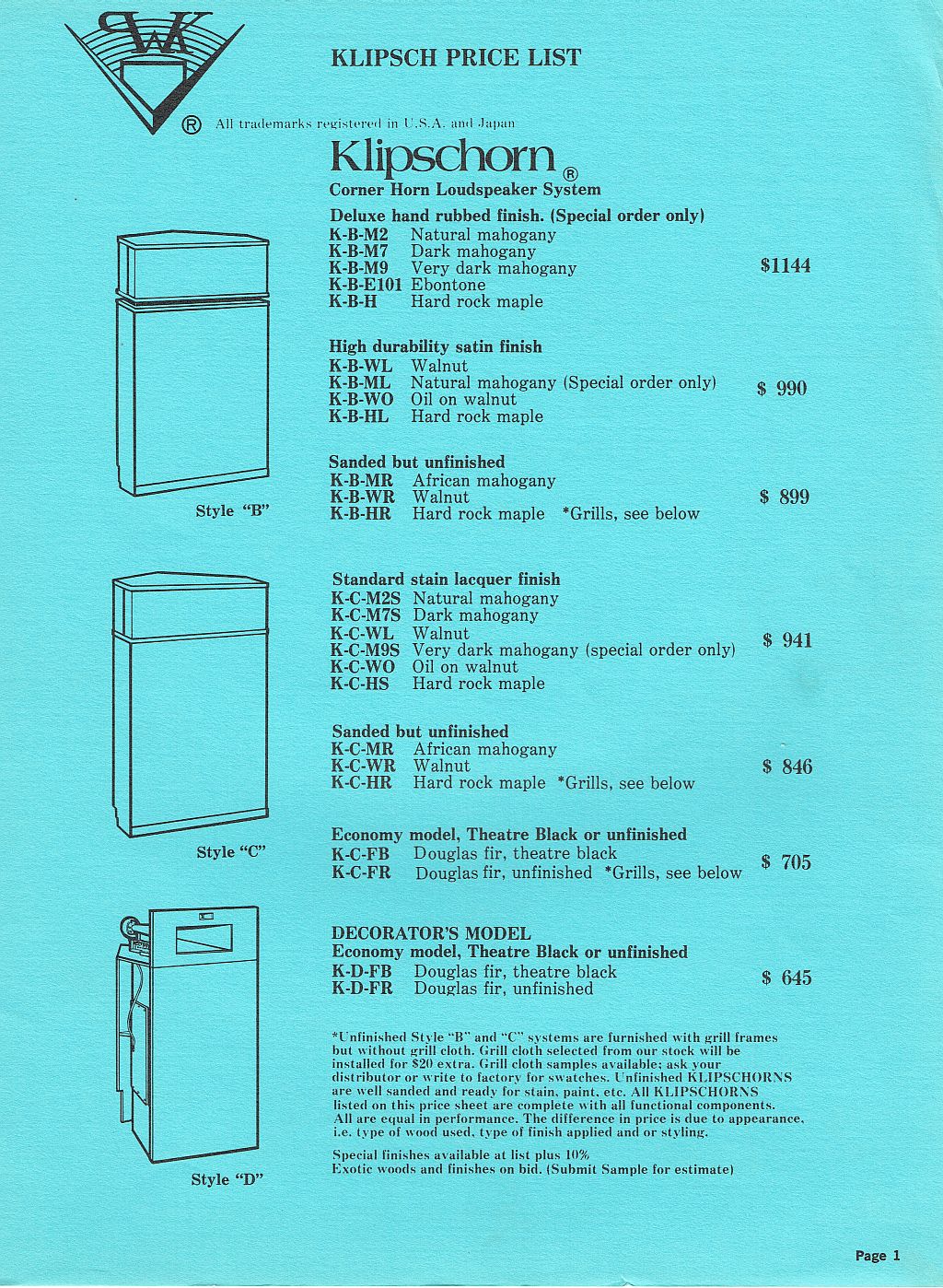
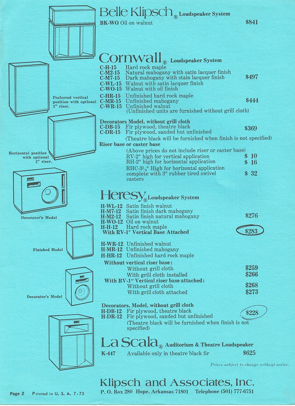
On January 21, 1976, I sent a check in the amount of $2,041.00 to Klipsch for my Rosewood Klipschorns and single Belle. The pricing is odd in that a July 1973 price sheet shows a single walnut Klipschorn listed for $990--$53.00 dollars more than my single rosewood Klipschorn! Back then, Klipsch as well as most every equipment manufacturer offered a dealer's salespersons "accommodation pricing" on their gear, hence the "Less accommodation discount for personal use of Lee Clinton". I don't think the Klipsch discount was 50% which was common for electronics manufacturers. The rosewood was Honduran, not Brazilian as Brazil had implemented an embargo on exporting rosewood wood logs. Before the embargo Klipsch did build gorgeous Brazilian rosewood loudspeakers on special order. The attached price sheet is from July of 1973. A pair of style B walnut Klipschorns sold for $1980.00. At today's dollar inflation rate, those would cost $10,606.00. The new Klipschorn pricing is about 13% higher than the cost adjusted for 1973 dollars. Lee
-
Please remember that Klipsch needs #6 lugs, a lot of links are to #8 lugs. Dennis, you are correct--I had forgotten the terminal cited was for a #8 stud. It will fit the Klipsch terminal block just fine width-wise. The Klipsch barrier block measures about 0.331" between the insulating ears. I did a little research on the Mouser site and came up with some choices for a terminal that will handle up to #10 wire and is suitable for a #6 stud. http://www.mouser.com/Connectors/Terminals/_/N-5g5u?P=1yzmo5bZ1yz0vctZ1z0xbyiZ1z0xbx2Z1yqs5ojZ1z0xbvs Note there are different styles of terminals, locking fork, block fork, spade tongue, ring, etc. All listed will fit the #6 screw just fine--it's just a matter of personal preference. You'll get maximum metal-to-metal contact with the ring terminal, but you'll have to remove the screw each time you want to change connections. I like the locking fork type because it won't fall off the barrier block if the screw is loose. edzu1234, you can click on the Data Sheet for each terminal to find out what the base metal is; some are copper while others are brass. All are generally bright-tin plated to keep oxidation to a minimum. Lee
-
You wrote: Does any know where I can buy Small Copper Spade Connectors that will handle 10 to 12GA speaker wire for La Scala Crossovers. Thank you in advance. The best I've found for #10 wire and the Klipsch barrier terminals are the 3M BS-33-8-P. While they are a crimp-on style, I just solder the wire to the terminal without crimping it. You can order the BS-33-8 which is uninsulated and use heatshrink (for appearance) if you are soldering it. The 3M terminals are copper base metal with a bright-tin coating. Mouser Electronics has been my go-to source for many years. http://www.mouser.com/ProductDetail/3M-Electronic-Specialty/BS-33-8-P/?qs=sGAEpiMZZMvz8LftK4jermgtdJWRly%2fklyjIGBpEj30%3d http://www.mouser.com/ProductDetail/3M-Electronic-Specialty/BS-33-8/?qs=sGAEpiMZZMvlX3nhDDO4APO3uE60z4QokrlD21fAn%252bg%3d Lee
-
Great Deal Crossover Upgrade by ALK
Arkytype replied to joessportster's topic in Technical/Restorations
Deano, You wrote: Data on Litz performance was posted here long ago. Yeah, I found the data on a nine-year-old thread where you were also praising the Litz coils to high heaven. Oops! I have listed below some good reading for those willing to set aside their prejudices. You wrote: I also won't be using Litz coils because I don't like the way they're made. They do measure a little better in the area that counts, but the loss reduction really becomes a non-factor as soon as the midrange and tweeter output is reduced. In other words, you gain a little and then lose it when you attenuate (perceptually) -- it's much to do about nothing. Coils should have no air between their windings and the windings need to be rigid. Just in case you’ve forgotten all that Al taught you about network design for the past 10+ years, here’s a quick refresher: The total insertion loss of a network is an aggregate of all the losses of each component. To go gaga over the use of some magical dielectric in a capacitor and ignore the fact that the inductor is the weakest link in a network is folly. While the "Q" of a low-quality capacitor might measure 200, the best inductor might measure 100. Litz wire inductors are demonstrably better than solid wire or foil inductors at tweeter frequencies. When you shelve the midrange or tweeter output level external to the filter, the advantage of a Litz wire inductor is that it becomes frequency and level independent. To say that their advantage is a non-factor as soon as the midrange and tweeter is reduced indicates the shelving was done within the filter or that the designer does not understand the fundamentals of filter behavior with losses. Coils should have no air between their windings and the windings need to be rigid. Why don't you offer some concrete evidence to prove this; better yet, post a link that everyone can read for themselves. I suspect this quote is just like one of dozens I've read that you've posted over the years---just subjective blather that some low-information members take as gospel. Posted by Deang on 03 July 2006 - 11:30 AM in 2-Channel Home Audio Steep slopes. The best imaging networks I ever heard was Al's ESNs. Posted 17 October 2015 - 09:23 PM I don't care for the ESN designs. The sound is dry, two-dimensional, and the transients are practically non-existent. In small rooms, you can hear the sound moving between the drivers, which has to be one of the most unnatural phenomena I've ever experienced from a loudspeaker. Posted by Deang on 28 March 2008 - 06:25 AM in 2-Channel Home Audio The key to surviving on the Klipsch forum is saying one thing and doing another. Do as I do not as I say. You wrote: Stop trolling. When you stop making open-ended statements such as, "Coils should have no air gap." and not continue the sentence with "because my measurements confirm such and such or, here's a peer-reviewed paper showing the advantages of a coil with no air gap.", then I'll stop "trolling". All I'm doing is calling into question your unsubstantiated statements. If you take that as a personal attack, then run tell a moderator that you are being picked on. https://community.klipsch.com/index.php?/topic/151287-foil-inductors-why-the-new-trend/page-2 https://community.klipsch.com/index.php?/topic/66857-inductor-face-off-ii/ Lee
-
Great Deal Crossover Upgrade by ALK
Arkytype replied to joessportster's topic in Technical/Restorations
Deano, You wrote: I also won't be using Litz coils because I don't like the way they're made What is it about the construction of a Litz wire inductor that you don’t like? The shape? The specific gravity? Then you wrote:They (Litz coils) do measure a little better in the area that counts…….. What parameter did you measure with your $44.50 LCR meter? Certainly not Q, not dissipation factor, not accurate DCR. And finally, you wrote: Coils should have no air between their windings and the windings need to be rigid. What proof do you offer to support this claim? Do you have definitive measurements that show the superiority of, say, a foil wound inductor over a Litz wire inductor? Here’s a quote that’s been hanging above all my measurement benches for the past 35+ years. It’s as applicable today as it was in 1883. Perhaps you should heed Lord Kelvin’s advice. I often say that when you can measure what you are speaking about, and express it in numbers, you know something about it; but when you cannot measure it, when you cannot express it in numbers, your knowledge is of a meagre and unsatisfactory kind; it may be the beginning of knowledge, but you have scarcely in your thoughts advanced to the state of Science, whatever the matter may be. Lord Kelvin, 1883 Lee -
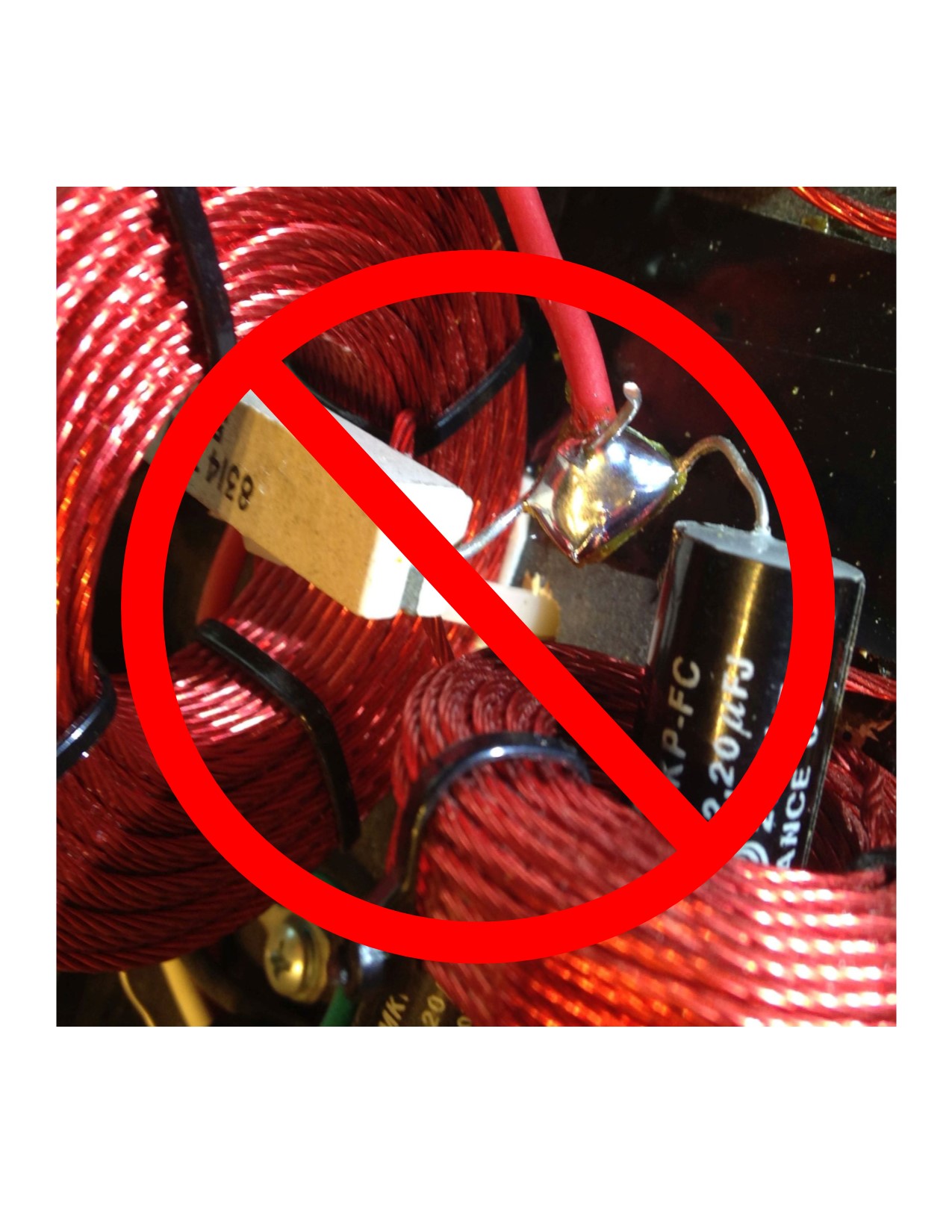
Deano, You wrote: Those aren't swamping resistors. One resistor is in series with the HF driver and is used to attenuate the output of the driver. The other three resistors are part of three independent LCRs used to correct for aberrations in the frequency response. Gosh, I didn't think you'd swallow the hook line and sinker. It was a comment made in jest. Tell us more about the three independent LCR sections. What aberrations are you trying to correct? Do you have measurements to share? wvu80, You wrote: Lee, what are you calling a swamping resistor? Would that be the four pink resistors on the side closest to us? A quick search of past forum posts will yield plenty of info on Al's use of a so-called swamping resistor to minimize load impedance variations to an amplifier. Lee
-
Great Deal Crossover Upgrade by ALK
Arkytype replied to joessportster's topic in Technical/Restorations
Put your pom poms down and think about your own character here. He's not welcome here (once again) and If you are going to keep chumming his business there will be plenty here to add a negative to that as a warning to "unknowns" about doing business with the jerk. Wow! is that a threat to Dave and others for exercising his free speech? What rank do you hold in the Thought Police? Lee -
That sucker's got four swamping resistors! Lee