Arkytype
-
Posts
448 -
Joined
-
Last visited
Content Type
Forums
Events
Gallery
Everything posted by Arkytype
-
Chris, I know Al didn't send that email to John and I hope my wording and intent was clear that he didn't. Until John fesses up, we'll never know. Lee
-
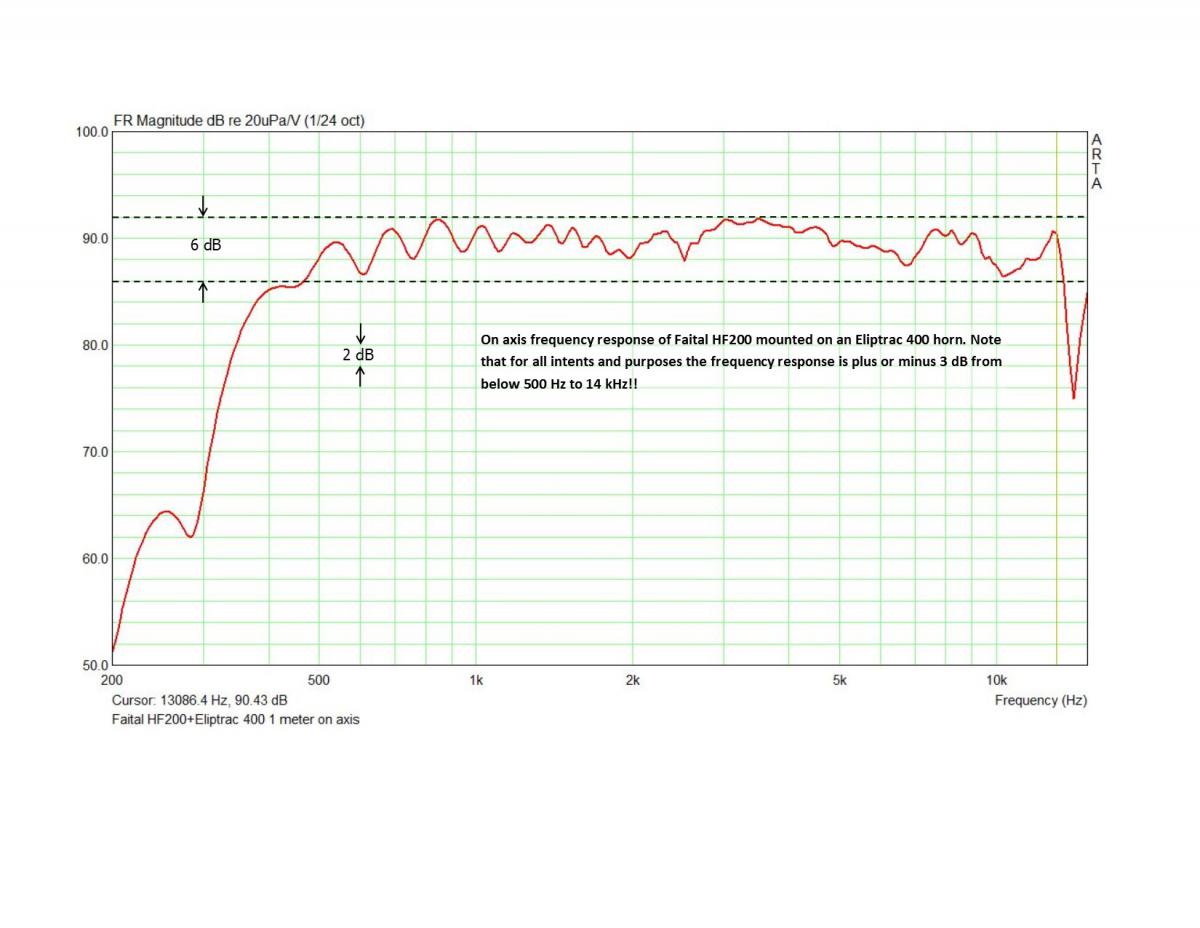
John, You wrote, “A member of this forum emailed this plot to me. It's a measured response of the B&C DCM50, a JBL and the K55M taken by a supplier that markets the B&C driver (the middle plot in the attached).” That “supplier” you knowingly failed to credit is Al Klappenberger who posted it on March 11, 2010. Now why on earth would you want to cite one of his measurements when you’ve recently said the following about (or to) him: October 19: In reply to one of his impassioned posts, you wrote, “No one cares.” October 21: “W Tee Eff, what can you do other than do what the ALK expects of you?” October 25: “Why should I waste my time with you (ALK) when you read (or comprehend) 1/2 of what's provided to you?” November 8: After dtel’s wife wrote, “one (ALK) has already been banned”, you wrote, “Mission accomplished.” I would call into question your double standard of behavior. On the one hand you damn Al and on the other you choose to use something he posted that might corroborate a point you are making. You wrote, “Given the enormous popularity of this driver, it suggests that this response, as Shakespeare would say, is much ado about nothing....” In reply, I’ll quote PWK who wrote in the February 1977 Dope From Hope, “The midrange is “where we live”; this is the frequency range where the ear is most sensitive to both tonal anomalies and to distortion.” (emphasis mine) The attached plot was made by me, not Al and shows an alternative to the DCM50+Selenium horn that you are offering. It’s a Faital HF200 mounted on Dave’s Eliptrac 400 horn. Now, what’s not to like about that on-axis response? Yeah, it’s a more expensive combination but worth saving the extra shekels for IMHO. You wrote, “A member of this forum emailed this plot to me.” If this is true, then you have admitted to violating Christy’s rule against posting emails and you should be given nine Warning Points. OK, Christy, did John cross the line here? Rules are rules. Here’s what she wrote on November 7th, “Posting by "proxy" is not allowed on this forum. I'm hoping members are not engaging in this type of activity. Posting of messages between parties, private emails etc. are also not allowed. There will be no more verbal/written warnings in this thread. Next step is nine warning points or being banned.” (emphasis mine) Lee

-
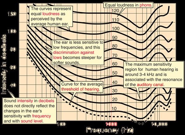
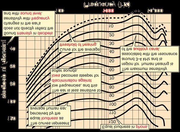
Deano, You wrote, Hey, check it out -- human hearing has a natural dip between 2000 and 5000, and it's a good one too. It looks like John couldn't have picked a better spot for his aberration -- chances are, it's probably not even audible! :-) Are you serious? You are reading the curves bass ackwards. The curves are called "equal loudness" not "frequency response of the human ear". Human hearing doesn't have a "dip", it has a "peak" in the 2-5 kHz range. Click on the show entire loudness curve set then add discussion of curves as annotation. The easiest way to visualize the human ear's "frequency response" is to flip the curves as I've done for you. Lee
-
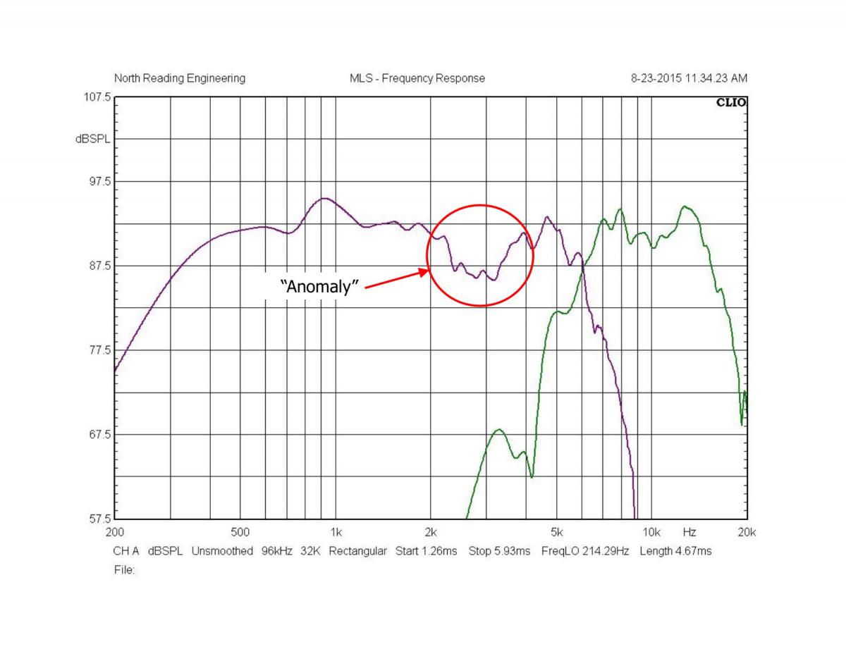
Mike, You wrote, John is the only guy here focusing on the acoustic response. You other three couldn't voice a system to save your life. If the attached plot from John's website is an example of his voicing skills, then, yeah, we three could probably do as well. That response droop is where our hearing is most sensitive and is somehow caused by the horn+driver+network interaction. Here's what John wrote about the response "anomaly", Are the responses perfect? No. Can I eliminate that response anomaly? Yes but it will add to the package and that adder is about $200 to the overall cost. Maybe I'll add it as another network option. FWIW, I've measured a lot of horns including ones made by folks that post on this site. I've also measured the response on networks made by others. From where I'm at, this setup can compete with any of them. Lee
-
The first part of my post was taken from Dean's re-posting of an older thread in which John Warren asked Al about his networks. I guess Dean thought he'd embarrass Al by bringing up a ten-year-old thread. The balance of my post was simply an attempt to refute the assertions John made back then. They are still relevant today. Lee
-
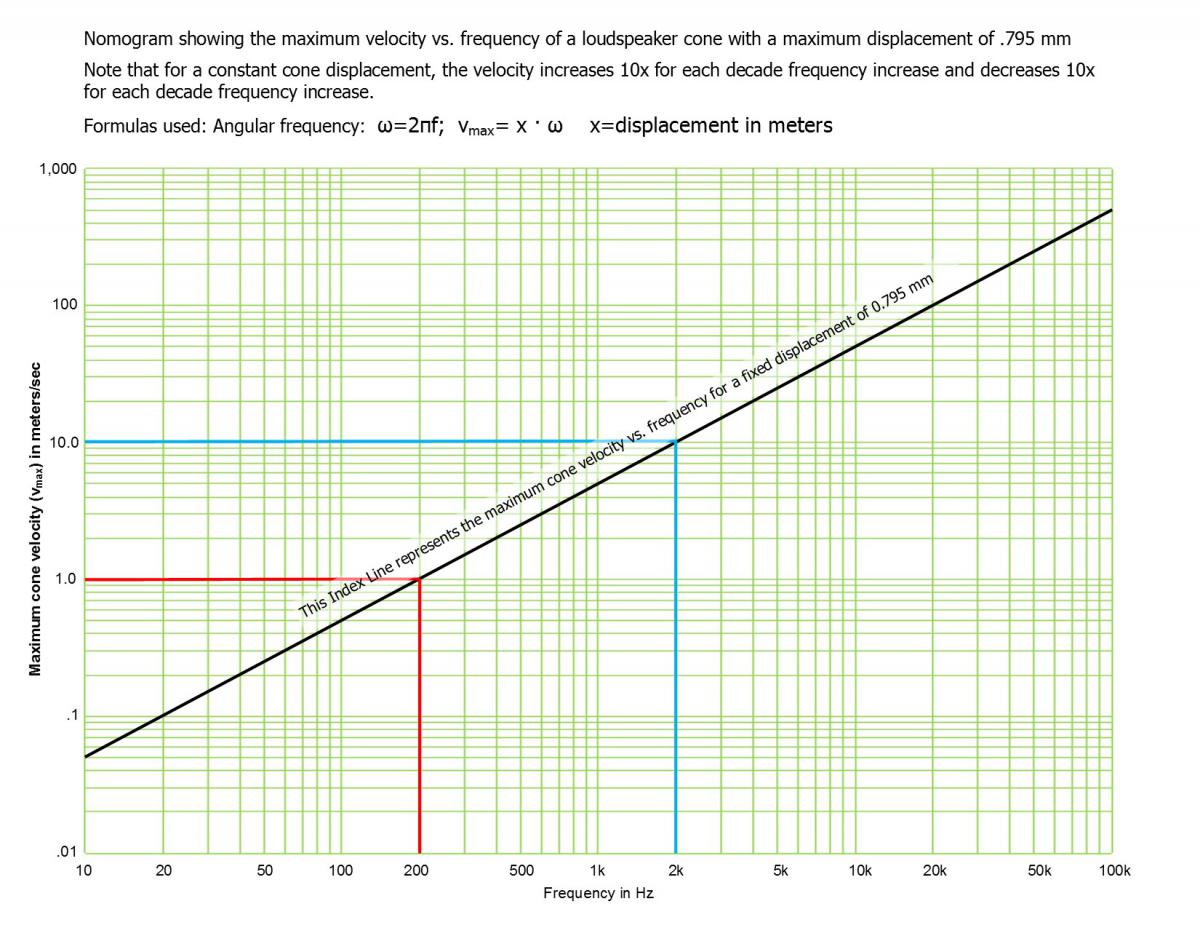
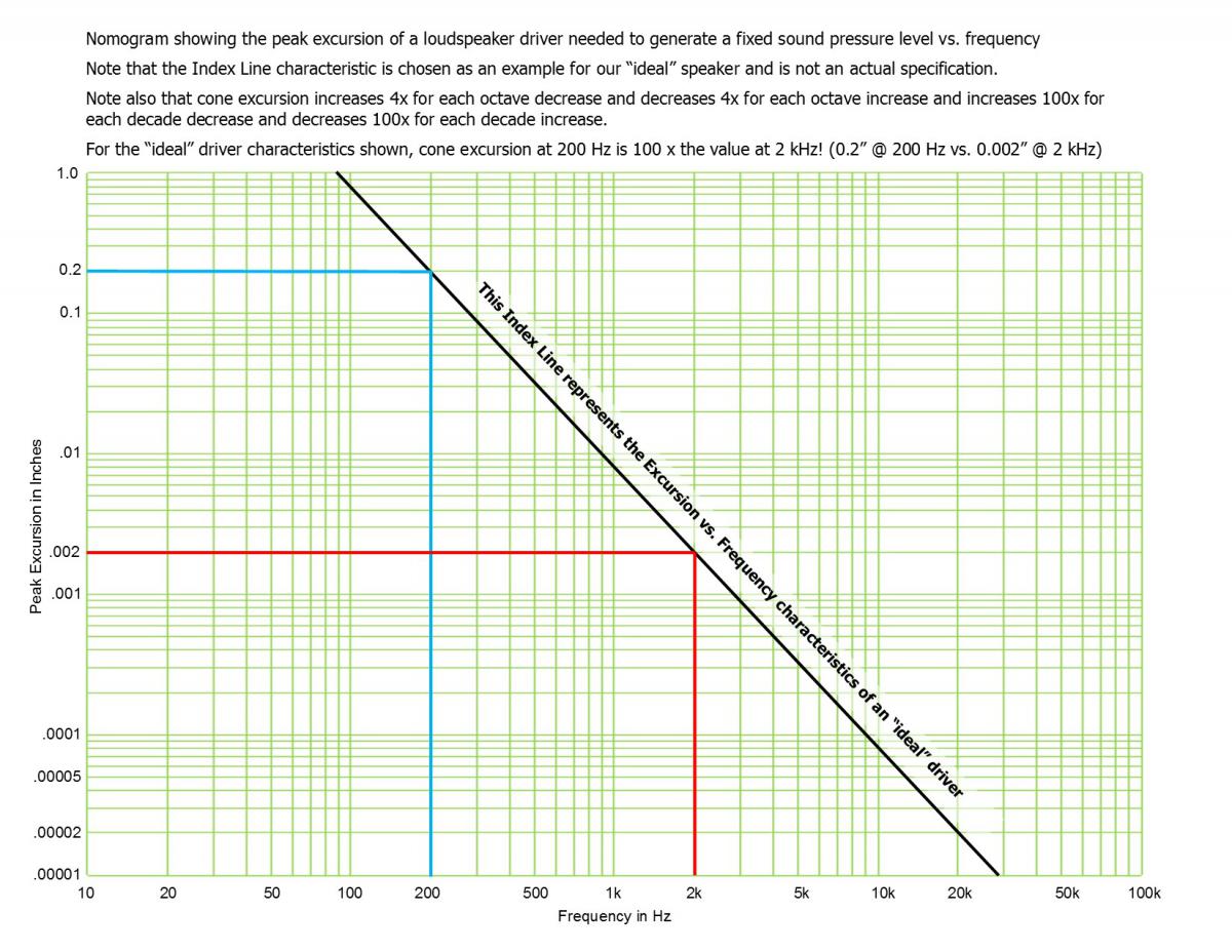
Deano wrote: I posted the old link because John asked a question. The question was in response to a statement by Al. The statement was this: "The very best way to transfer power is to match impedance." I tried for a decade to understand this, and I used to tell Al, quite often actually - that John is not a dumb guy, that a guy who spends his life studying motors, might be trying to teach you something important. John Warren to Al: '"You must explain to me. To obtain a linear spl [sic] as a function of frequency a loudspeaker(s) cone must have a constant acceleration, independent of frequency, over the entire bandwidth of operation. That criteria is fact and is a topic that has been discussed for many years in the literature (Small, Locanthi as examples). Small, in fact, has a paper that explains how to preserve a constant voltage transfer in a passive network, the necessary requirement for constant cone acceleration. He states, "consideration of the electroacoustic behavior of the common loudspeaker drivers leads to the general crossover network design requirement of constant total voltage transfer." (Proc. IREE Australia 31, 1970) That said, how can a constant power transfer satisfy this criteria? That force that drives the cone is F = (Bl) E / (Zc + ((Bl)2/Zm)) where: B = flux density in gap l = length of wire in gap Zc = dc resistance of coil and coil inductance Zm = back EMF E = driving voltage What Small is saying is that above resonance (i.e. in the operating range), the force driving the cone is "essentially" a linear function of the driving voltage E. Since the sound pressure is F/Sd (where Sd is the radiation area), the sound pressure then becomes a linear function of the driving voltage. And like I said before, for a fixed sound pressure (i.e. flat fequency [sic] response) the only thing that is needed is a constant acceleration. You fail to see that the integration of filter theory REQUIRES A FUNDAMENTAL UNDERSTANDING of the interelationship [sic] between the acoustic mass, the electrotransduction [sic] factor BL and how it is reflected back to the amplifier. You deal with everything from the "microwave" world which, last I looked, has NOTHING whatsoever [sic] to do with sound reproduction. I'll assume that you will NEVER be able to explain why the "constant impedance" network is an advantage from a SPL vs. frequency perspective and not a "microwave" perspective."' John, First, let’s examine your premise that in order to have a “linear SPL as a function of frequency a loudspeaker’s cone must have a constant acceleration, independent of frequency, over the entire bandwidth of operation.” After reviewing my technical library of books and papers, I could find no example where the term “acceleration” was used to describe the motion of a loudspeaker cone. Acceleration is not even in the indexes of Harry Olson’s Applied Acoustics or Leo Beranek’s Acoustics . and these guys literally “wrote the book” on acoustics, loudspeakers, measurement, etc. I believe that in the context of our discussion here, the proper term to express the motion of a loudspeaker cone is velocity, not acceleration. I’ll leave it to the Gentle Reader to look up the difference between the two related terms. Olson writes, “The acoustic power output is the product of the resistive component of the air load and the square of the cone velocity.” Beranek writes, “The performance of a direct-radiator loudspeaker is directly related to the diaphragm velocity. Having solved for it, we may compute the acoustic power radiated and the sound pressure produced at any given distance from the loudspeaker in the far field.” (emphases mine) A loudspeaker cone can only experience an acceleration if the velocity vector changes amplitude or direction. As you can see from the attached nomograms, there is no way a loudspeaker cone can experience “a constant acceleration”. It doesn’t matter whether the loudspeaker is reproducing a steady tone or a movement from Carmina Burana, there’s no “constant acceleration”. With a 2 kHz tone, our displacement limited loudspeaker cone is experiencing a velocity of 10 m/sec away from the magnet for the first half of our 2 kHz sinewave, stops and undergoes a 10 m/sec velocity towards the magnet and repeats. The acceleration is constantly changing with either a positive or negative vector—not unipolar as your wording would imply. Or am I missing something here? Second, you wrote: Small, in fact, has a paper that explains how to preserve a constant voltage transfer in a passive network, the necessary requirement for constant cone acceleration. Please explain why a constant voltage transfer in a passive network is a requirement for a constant cone acceleration. I just explained why a loudspeaker cone cannot experience a constant acceleration. Or am I missing something here? Third, Small’s paper is only valid for a two-way loudspeaker system and only if the crossover network is a first-order (6 dB/octave slope). Knowing that, it imposes unrealistic constraints on someone wanting to connect two loudspeakers using his “constant voltage” crossover network scheme. Small writes, The derivation of (equation 1) assumes two conditions: that the drivers are mounted closely together and that they are identical. Oh, and don’t forget, “…the drivers used must have a useful frequency ranges which overlap by about four octaves. Huh?? John wrote, I'll assume that you will NEVER be able to explain why the "constant impedance" network is an advantage from a SPL vs. frequency perspective and not a "microwave" perspective.” In the Conclusion of his paper, Small writes, For systems having unavoidably large driver spacings, there is no perfect crossover design. Intuition suggests, however, particularly when room reverberation is considered, that in this case constant power transfer (constant-resistance) networks would provide the best results on average. Looks like to me Small has just vindicated Al’s use of constant power transfer networks. Or am I missing something here? Finally, in the words of Al K., The requirements for filters to work at microwave are so stringent that a microwave design will operate easily at audio. The designs that can get by at audio will fail miserably at microwave. It shouldn't take a genius to see why microwave standards applied to audio is an improvement. Lee Constant-Voltage Crossover Network Design.PDF
-
Deano, I can't vouch for Al, but I've had my daily dose of Steely Dan. How 'bout you? Lee
-
Deano, you wrote: I think I built the network below about ten years ago. I then took Al's idea of lifting the common connections for the squawker and added the two jumpers so all of the autoformer settings could be used. I then added the 3rd order tweeter section, and the "Super AA" was born. You actually can't let the BMS roll off like the K-55, it extends out quite a bit further -- it needs at least the single coil. Al of course gets full credit for applying the resistor (swamping resistor) in such a way as to turn the autoformer into a standalone attenuator -- the rest of us just found some interesting iterations on the theme. However, we know where credit goes, to whom, and for what. I'd say the credit should go to the guy who designed the Super AA in the first place. Lee
-
Travis, You wrote: The smiley faces don't work. You were more arrogant and insulting in this thread than Al was, even worse you are his tool. Which is a shame given the length of time you have been on here and the knowledge you have shared on here previous to this, without being arrogant or abusive. Especially in the area of reel to reel. Now he is gone, again. So I guess the question you probably need to be asking yourself is "am I on their radar?" Yes, you most certainly are. Do you care? Time will tell.. Will you continue to defend Al 's behavior and actions or act as his conduit/proxy? That is of course up to you. I would say that you are probably going to need a serous attitude adjustment if you are planning on continuing that for any significant length of time. The Dark Side has its perquisites. Lee
-
Dean, You wrote: "Lee, There isn't anything in this thread that correlates to the older thread." Well, let's see; on March 22, 2005 you were still questioning how Al's swamping resistor worked by writing," Al, can I play Angel's Advocate here? The resistor across taps 0 and 5 on the autotransformer -- what is the difference between putting it there, or at the amp's outputs, or the speaker's input terminals (it is after all, input to ground). Power is "wasted" to flatten the impedance -- I mean, that's what swamping resistors do. By adding it into the network, it's probably adding an additional 3 to 6db of insertion loss (as compared to the AA)." And the next day, I'll be darn if you didn't post a link to John Murphy, just like you did on October 14, 2015. Shall I find more citations from your ten-year-old posts that don't correlate with the current thread? Despite the many hours Al spent with you patiently explaining his microwave filter-based approach to network design, the how and why of a swamping resistor, how two diplexers could form a bandpass filter, why minimizing driver overlap is a good thing, as well as other "basic" filter knowledge, you still seem to reject all that design know-how and praise a low order filter's ability to allow more than one driver to radiate the same program material. I'd include helpful links for you to explore here, but it would be a waste of time. For the Gentle Reader who has not opened the 10-year-old link Dean provided, it'll be the best explanation of how and why Al designs his networks. Lee
-
"It's like déjà vu all over again." Posted 28 October 2015 - 08:01 AM 10 years ago: https://community.kl...t acceleration Dean, I'm surprised you'd have the nerve to post a link to a ten-year-old thread which, for the most part, covers what has been discussed in this thread ad nauseam . Ten years has intervened since those posts and what have you and John learned about network design? Apparently nothing as you both are bringing up the same misstatements, misconceptions and opinions. Back then, Al was a little more reserved in his posts and was simply trying to educate, correct your false statements/premises and set the record straight on how and why he designs his triplexers the way he does. The tenor of his latest posts are due, in part, to the fact that he's tired of explaining what you and John failed to learn ten years ago. Now you be sure to run to the nearest Moderator and complain that Lee is picking on you again. A friendly note to the powers that watch over our discourse: If calling a fellow forum member a sock puppet and posting the symbol for effyou (it's still up on the web site last time I checked) and a poor taste reference to Belle Klipsch is not an example of "condescending, rude behavior.", then this post should pass your zero tolerance sniff test. Lee
-
dtel’s wife wrote: This is uncalled for. Anymore after this will result in warning points. John Warren wrote: 1. The NRE-net has a very large reactance associated with the autotransformer, horn reflections, etc. The reactance is highlighted by our little mountain climber (let’s call her Belle). I wrote: Hey John, If you see Belle while mountain climbing, say hello for us! I don’t think John’s “Belle” has anything to do with the late Belle Klipsch. If it did, then yea, it was uncalled for and I certainly would not have written what I did. Lee
-
Hey John, If you see Belle while mountain climbing, say hello for us! Lee
-
Dean, You wrote: Using a 100 watt amplifier, a tweeter with an 18dB/octave slope, crossed over at 5000Hz, will receive 1.6 watts from the amplifier. That same tweeter, crossed over at the same 5000Hz with a first order or 6dB/octave filter, will get hit with 25 watts. I’ll give you the benefit of the doubt and express your statement in terms of what you probably meant to say. Otherwise it is meaningless. For a 1st order HP filter with a crossover frequency, Fc of 5 kHz, power is reduced by 6.02 dB at each octave frequency below Fc. For example, at 2.5 kHz, power will be -6.02 dB (1/4th or 25 w); at 1.25 kHz, power will be -12.04 dB and so on. For each higher order filter, the power reduction will increase an additional -6.02 dB per octave. Lee
-
Dean, On October 18 (Post #109) you wrote: “Besides, I never claimed to be a filter designer or an engineer - just someone who knows how follow a schematic, and make a nice build out of it.” On October 23 (Post #255) you wrote: “My only possible criticism to building Diplexers for loudspeakers lies with the low pass. The idea of course is to match the impedance of the high pass to the impedance of the low pass. The high pass is swamped back and stabilized, and the low pass is based on this idea of 6 ohms in series with 1mH of inductance. However, the impedance of the low pass is not static, but dynamic - it's reactive and going all over the place. Then we have the effects of power and thermal compression -- any numbers derived during test conditions go out the window under a real load over any extended period of time.” And, “What has always sounded best to me is the single coil in series with the voice coil, and the lower you can get the DCR the better it sounds.” Parlez-vous filters? Boy, you sure sound like an old-time filter designer there! I can just imagine the Pickett & Eckel Deci Log Log Duplex slide rule hanging off your belt…… But then you wrote, “People should try to see crossovers as filters (because that is what they are), and with having the same effect as tone controls -- because ultimately, that's exactly what they do.” So, I’m sitting in my Eames Lounge chair listening to Béla Bartók’s Romanian Folk Dances on my Rosewood Klipschorns and, gosh darn it, that violin just doesn’t sizzle like my Guarneri. "Oh, Jeeves, be a good man and change the taps on my tweeters. Let’s try +3 dB this time. And bring me a hot toddy, I’m feeling chilled. For Gawd's sake, try not to get fingerprints on the wood this time." Yeah, I suppose you could torture the definition of a tone control to include a crossover network but it’s a poor analog…….. Lee
-
On 10/22 @ 0503, John posted with the words "microwave engineers" highlighted. Al was noting that microwave engineers use the Smith Chart as part of their filter designs. Lee
-
BTW: The Smith chart is used by microwave engineers because the outer circle represents 360 degrees down a transmission line. John, Dean, et al, I wouldn’t be so hard on Al for using “microwave engineers” techniques for designing his filters. Would you be equally hard on PWK if he had used similar techniques? Well, in fact, he did! Check out Volume 7 No. 1 (January 4, 1966) issue of The Dope From Hope where PWK acknowledges learning his “Transmission Lines and Wave Filters” from Dr. Frederick Terman in 1933. At that time, transmission lines and wave filter applications dealt almost exclusively with radio engineering. The term "audio engineering" wasn't in the lexicon of the time. Who’s Terman? One of the giants in early RF design and product development. Note that “RF” stands for radio frequencies, not audio frequencies. His books include: Fundamentals of Radio, Radio Engineers’ Handbook, Radio Engineering . Notice the word “radio” in those titles; Terman taught RF-based engineering and the wave filter topologies developed in the early days of radio. While Stephen Butterworth’s seminal paper, On the Theory of Filter Amplifiers was published in 1930, the paper was all but ignored for years. As PWK wrote in the above cited Dope From Hope, “Practical applications of wave filters to loudspeakers has been studied for over 30 years.” In the Volume 11, No. 2 Dope From Hope, Note that PWK is still tinkering with “constant-k” filter topology developed for radio engineering. The preceding was not in any way to denigrate the accomplishments of PWK. It was only to point out that the use of crossover networks for audio frequencies is a direct evolution from filter theory developed for radio and transmission lines. I’m sure the “family tree” of passive filter design has many branches and it would be an interesting exercise to see how topologies such as Butterworth, Bessel, m-derived, constant-k, Cauer, Chebyshev, etc. developed. Lee
-
John, You wrote: "what can you do other than do what the ALK expects of you?" I guess someone at Klipsch removed the "double you tee eff" you started that mangled sentence with. While Al & I both suffer fools lightly, neither of us "expects" the other to do anything. Fortunately, we are of like minds on this thread's topic and as a result, our respective posts may overlap with similar sentiments. For those of you who don't know why John posted the two un-captioned Bode plots 10/21/15 @ 8:47, I'll tell you. The Bode plot on the right was a measurement by the late Richard C. Heyser, inventor of Time Delay Spectrometry or TDS. That Bode plot is part of the test report of a Klipschorn which appeared in the November, 1986 issue of Audio magazine. Guess John thinks that because Dick Heyser, PhD, presented his Bode plot, ol' John was in good company by posting his. The only thing you and the late Dick Heyser have in common is that you both have PhD degrees. The primary difference between you and Dick Heyser is that only one of you seems to be educated beyond his intelligence. Lee
-
Diddled by the dangling dong of Destiny!! OK the emoticon should be the lower case second letter of the English alphabet surrounded by parentheses. Lee
-
The emoticon should have been a (. Thanks Obama. Lee
-
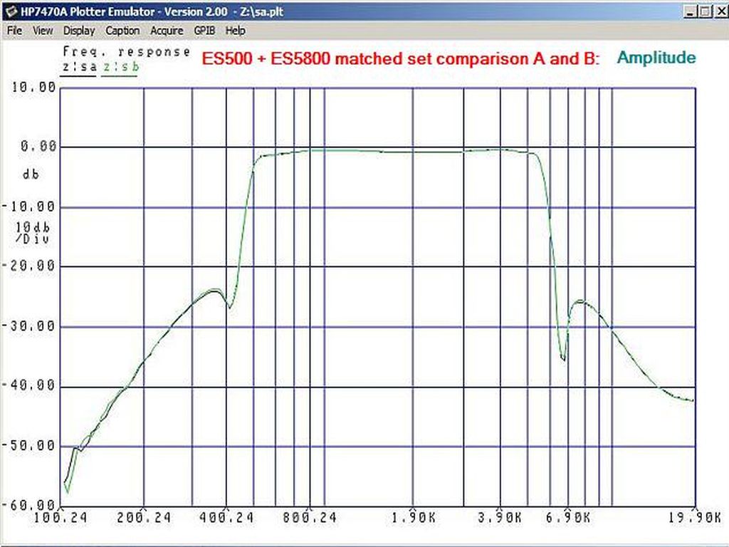
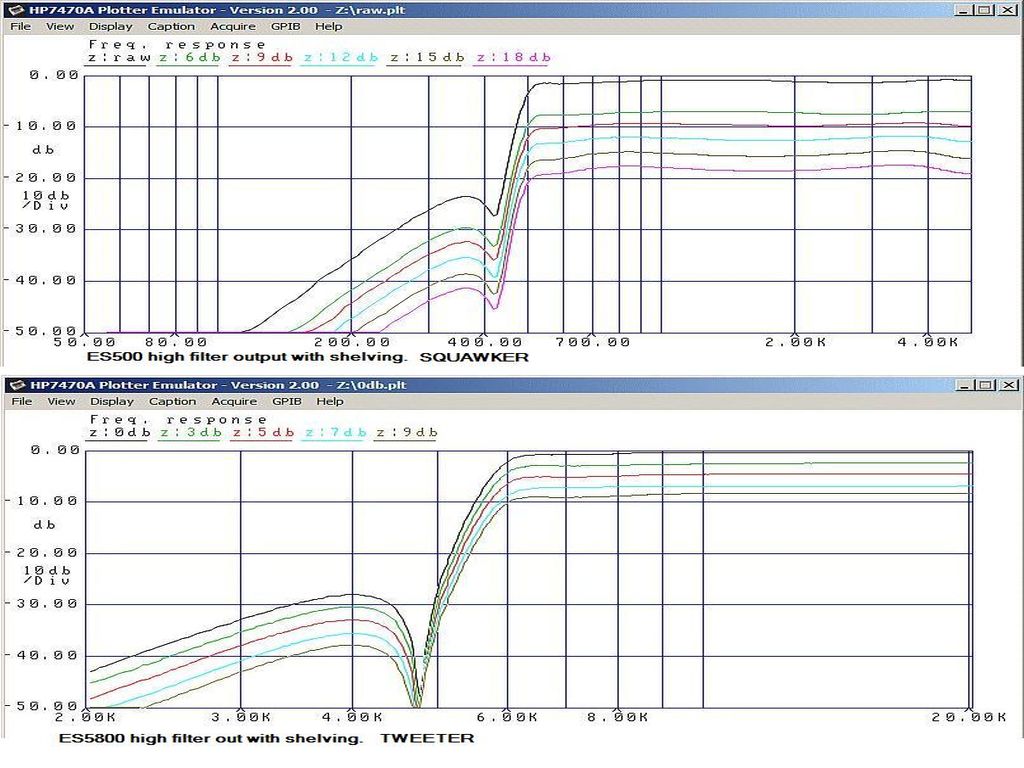
John, I was able to "reverse engineer" your network schematic in less than a half hour. Anyone can look at the images you posted, draw out the components and follow the connecting wires. With the exception of an unswamped autoformer, it's a pretty generic design. The schematic was then sent to Al who used his software to compute probable component values. If other forum members would like to see the probable component values, I can post it. The reason Al asked you to provide those electrical plots was, (a) to determine if you knew how to measure the parameters in question and, ( if you haven't done the measurements yet, what the heck are you doing in the crossover network business? So, now that we've reverse engineered your "autotransformer based crossover network" to our complete satisfaction, what excuse will you now proffer not to publish them? Attached is a plot of two midrange ES sections showing how closely each pair of networks Al builds is matched. Do you measure each pair of network you build to insure similar matching? Wanna share a plot? Another plot is the complex impedance of an ALK network as seen by the amplifier. The third plot is the shelving range available for the ES500 high filter output and ES5800 high output. Not bad for a SOCK PUPPET!! SmartWool Sock Puppet
-
John, You wrote: "...please note that I publish plots for the very sake of exposing every possible parameter I can. I publish everything." We've seen acoustic plots of your stuff. Now how about publishing some electrical plots of your network showing the filter slopes and maybe one showing the complex impedance; Zo vs. phase will do nicely. For completeness, how about a set with passive driver loads and then a set with the actual drivers (your choice of tweeter). Lee
-
Dean, You wrote: "It has always been an unspoken rule that you don't enter another vendor's thread unless you have something positive to contribute. The proxy posts and idiotic emoticons were clearly an attempt to pollute John's thread." So, if a competitor to Klipsch Group, Inc. is hawking a questionable "upgrade" to one of their premier products, the Klipschorn, we as good forum members should either falsely praise the product with huzzahs or remain silent. Not gonna happen. Some forum members have made significant upgrades all across the Klipsch product spectrum. Dave Harris in particular has developed well over a dozen improvements, the most notable (at least to me) being the Eliptrac 400, a huge improvement over the K-400 horn. My first post to John was simply to question why two frequency response graphs he posted showed a 6-7 dB droop between 2 kHz & 4 kHz. His reply was, "But is [sic] sounds pretty damn good and no dulling as you're inferring." Boy, if I'm a potential customer for one of his (taking a big breath here) "Top section baffle insert designed to accommodate three driver assemblies with autoformer based crossover network", whew, I'd want more than a verbal assurance that the "anomaly" is not going to detract from my listening enjoyment. As an aside, John can call his network whatever strikes his fancy; but to say it's a transformer based crossover network is like a loudspeaker manufacturer saying their product is a woofer-based loudspeaker---it makes no sense. The autoformer, capacitors and inductors all work together as an ensemble to divide the frequency spectrum between the three drivers. No one component should be singled out like it's a feature. The probable reason PWK specified the capacitors the way he did was not because they sounded better than polypropylene or other types of film capacitors--he chose what was available at the time that had the necessary value and voltage breakdown. Film capacitors with those specifications were probably not in production "back in the day"; or, if they were, they were prohibitively expensive. But I'm only guessing. You wrote: "I use paper in oil and the wax paper Jupiters to retain the original sonic signature.... So, I don't see how you can get any closer to the original builds than what I'm doing." There are vintage car guys and gals who would never replace the drum brakes on their vintage Mustang with safer aftermarket disc brakes because they also want to be closer to the original build. They may also be closer to their maker when they have to make a high speed panic stop!! You wrote: "I don't care for the ESN designs. The sound is dry, two-dimensional, and the transients are practically non-existent. In small rooms, you can hear the sound moving between the drivers, which has to be one of the most unnatural phenomena I've ever experienced from a loudspeaker. Is this what we should expect from superior network design?" PROXY ALERT!!! DON'T READ BEYOND THIS LINE IF YOU DON'T WANT TO KNOW WHAT AL WROTE IN RESPONSE TO THE ABOVE STATEMENT I asked Al when you had an opportunity to listen to his Extreme Slope network. Here is his answer: "Dean's experience with ES networks was when I loaned him a set of ES400 + ES5800 which he stuck in his Klipschorns up in his attic loft. The room was too small even for Klipschorns, let alone extreme-slope networks! Of course the sound jumped around between drivers; he was sitting too close to them because of the size of the room! He simply was stuck with a low and unrealistic level which is a justification for driver overlap and the "singing in the shower" artificial ambiance it gives you." You wrote: "I am 100% done here." Dean, as you wrote, "I'm allowed to have my opinions." Hey, the more you reply the more you reveal--so keep it up!! Lee
-
Dean, You wrote, You had no business sending Lee into John's thread and then callously following along. However, some of us expected something from your end, because we figured the thought of John coming up with something for that set up was going to drive you nuts. As a rule I don't engage in a battle of wits with a half-armed opponent, but I might make an exception in your case. Al didn't send me into JW's thread; I e-mailed Al on 10/6 to let him know that I saw the post and pointed out some of the claims that were made. While Al may have strong opinions on a subject, he is his own man and doesn't "callously follow along" anything or anyone. You then wrote: I wanted you to patent the whole network concept, not just the swamping resistor, which I fully now realize doesn't work the way you think. Oh? Why don't you explain to Al and everyone reading exactly how his network really operates. Be sure to include a pole-zero diagram of the lowpass section so we'll know you aren't as full of cr@p as a Christmas turkey. Lee
-
Dean et al, Here are some of Al's design philosophies which you should already know by heart. They are taken directly from the "Questions, Answers and Downloads" section of his web site; so, technically, this is not a proxy post. "Providing a stereo amplifier with a constant 8 Ohms load is not actually required. Very few crossover networks designed by others are constant impedance. The stock networks for Klipsch Heritage speakers is all over the place. Some cause 8 Ohms speakers to look more like 70 Ohms in the midrange! The actual merit of a constant impedance is that it is the mark of a properly designed filter. This is a lesson learned through years of experience designing filters a microwave frequencies. With stringent requirements on "return loss" at microwave frequencies you quickly learn to do it correctly. There is simply no good reason why a network should NOT have a constant impedance! The fact that good amplifiers with high damping factors can handle bad loads is no more a reasonable argument for poor designs then a highway engineer would claim that a road should have lots of curves and bumps simply because cars have steering wheels and shock absorbers! Another way to put it is that a network that provides a constant impedance will sound better, not just because it loads the amplifier with a constant impedance, but because it is a correctly designed network. On the other hand, if you have an amplifier with poor damping factor, like a 5 watt SET, it will operate much better if it sees a constant impedance load. The frequency response can actually follow the load impedance curve!" Who would you want to buy an aftermarket network from; someone who has built and sold 1500+ "correctly designed" networks or one with a questionable design? You were given a golden opportunity by Al to build his Universal networks. How did that go? Is your lack of sales success with that network the source of your animosity toward Al or are you just a sorehead? Lee