Arkytype
-
Posts
448 -
Joined
-
Last visited
Content Type
Forums
Events
Gallery
Everything posted by Arkytype
-
Be careful what you wish for! Lee
-
Dean, you wrote, The swamping resistor is an intergral [sic] part of Al's designs. However, the ability to adjust the attenuation is more of a convenience feature. I personally don't think it's a requirement unless you like trying a lot of different horns and drivers. Moving the autoformer tap may be a convenience, but that’s no excuse for not using a 50 cent resistor to provide your amplifier with a more linear impedance load. You wrote: If you have something you know you want to stick with, know how much to attenuate the driver, and know what the impedance is at the crossover point -- you can use impedance scaling to find the primary capacitor value. I would imagine this is what John did, and it works perfectly fine. John’s one-solution-fits-all network and top section baffle require the customer to choose between two HF options on the front end. If the customer later chooses an alternate HF driver requiring a different crossover frequency, he or she will have to scrap the entire network. With the limited attenuation range of John’s autoformer, one is forced to stick with an alternative midrange driver with nearly identical sensitivity such as the B&C DCM50. Changing to a 16 ohm driver is out of the question. One of the great design benefits of Al’s family of crossover networks is that you aren’t stuck with a single solution. So, pretty much regardless of which Klipsch loudspeaker you own, you can upgrade not only the HF section by choosing from several aftermarket horns and drivers, but are able to choose the LF or HF crossover network that best matches your choice now and in the future. You wrote: There is more than one way to do something well. The swamping resistor is just one way of getting it done. With apologies to our porcine pets, adding a swamping resistor to John’s network would be like putting lipstick on a pig! Is using low-Q, lossy inductors instead of high-Q, low-loss inductors wound with Litz wire an example of “one way to do something well”? The Butterworth design topology John copied from Klipsch is old school at best. To paraphrase the late great Yogi Berra, the reason everyone uses Butterworth filters is because everyone uses Butterworth filters. This type of filter is all audio people understand and it’s what you get with the on-line crossover calculators. Looking at the schematic of John’s network (see my earlier post), one can see that he uses two Butterworth 3rd order filters with their inputs separated by the autoformer and a high-pass filter consisting of a single capacitor connected to the woofer. This design is flawed in-part because the reactance cancellation needed between the filter sections (to achieve a more nearly perfect and constant amplifier load) is absent. This clearly gives us a better reason to put the transformer at the termination end than for just the convenience of correct shelving! It is a win-win situation compared to a bad and outmoded design. You wrote: What about this guy (John Murphy), is he lost, or should we recognize his credentials and consider that he might actually know what he's talking about? The “guy” you are referring to is the well-respected John Murphy. Who hasn’t downloaded a free copy of his TrueRTA audio spectrum analyzer software? His DATS and WinSpeakerz programs are great, affordable tools. His paper represents a common-sense approach to crossover network design. However, with the exception of using a Linkwitz-Riley type filter in one of his examples, his discussion is centered solely on using the Butterworth type of filter.. I hope you aren’t trying to compare his design acumen to that of John Warren; it would be an insult to Mr. Murphy. You wrote: I don't like the proxy posting while Al plays the cheerleader. Seriously? So, you weren’t acting as John Warren’s proxy with your last two posts? You were certainly happy and willing enough to be Al Klappenberger’s proxy in these posts: https://community.klipsch.com/index.php?/topic/145971-new-tweeter/?hl=de120 Lee
-
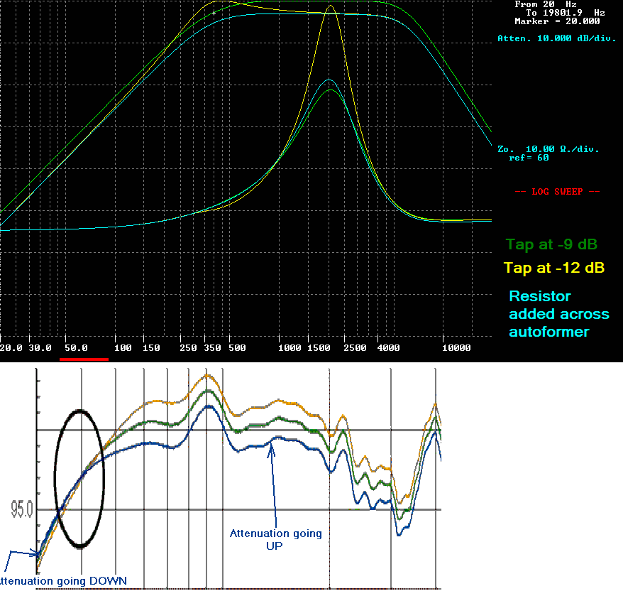
Hello All, Al Klappenberger has written me an e-mail which does a better job explaining how to design crossover networks better than I could ever do. So, for those of you who have missed Al K., here (unedited) is what he has to say about John Warren's "autoformer based crossover network": Lee, I'm sure you have noticed that I have been following this thread. I am writing you to help explain what is going on here. JW's web site states: "The autotransformer provides for the ability to change the midrange output. The so-called "swamping" resistor (or shunt resistor) across the input side of the autotransformer winding is not needed in the design." The acoustic plots he provides clearly show what has been pointed out by many people on the forums, and that is, you can NOT move the autotransformer taps without the electrical crossover moving on the Klipsch networks. JW has his autotransformer wired exactly as it is in the Klipsch AA network: before the squawker filter (which the AA does not have) and after the single capacitor of a 1st order 400 Hz filter (13 uF in the AA). What is not often noted is that moving the tap also causes the passband to tilt. This is shown on JW's plots by the fact that the curves of different tap settings move apart as frequency increases. It also shows the attenuation moves in the opposite direction below 400 Hz. It actually goes UP slightly with increased attenuation settings as the high frequencies move DOWN!! The reason is that the electrical crossover moves down allowing more energy at 400 Hz to get through to the driver. There is NO innovation here but rather a clear example of why you can NOT move the taps without adding a parallel "swamping" resistor to restore the impedance reflected through the transform back to where it was. I have attached a computer simulation study to illustrate the effect. The green curves show the frequency response and impedance seen by the amplifier in JW's network as closely as I can duplicate it. This is with the autotransformer set at -9 dB and the single capacitor selected to yield a 400 Hz electrical crossover. That is the small white "+" marker showing 400 Hz at 3 dB down. t The lower traces are the impedances seen by the amplifier. The yellow plot is after moving the autotransformer tap to -12 dB. No other changes. Note that the level above 400 Hz goes DOWN and the tilt becomes obvious. The level BELOW 400 Hz actually goes UP! The cyan trace is with a "swamping" resistor added across the autotransformer to reduce the impedance back to where it was. The passband frequency response is now flat and "shelved" like it should be. JW's acoustic plots show that the part values he used were picked to allow the 400 Hz ACOUSTIC crossover to stay in one place. This requires a HUGE amount of effort picking part values or, more likely, just plain luck just to avoid using a 50 cent 10 ohm resistor! Another problem here is that the lowpass filter connected to the DCM50 driver is designed for 8 ohms. A 16 ohm driver could NOT be used without totally upsetting the response. With the autotransformer wired between the filter and the driver and a 10 ohm resistor across the autotransformer, any driver impedance or sensitivity can be used simply by moving the tap. The 8 ohm filter will never see a load greater than 10 ohms. There will be no passband tilt and you will have a correct "shelving" adjustment. I suspect the real reason a special autotransformer was designed is because the original 3619 I used for years is no longer made. The new 3619-ET is available from Universal Transformer only to myself and Dean Wescott (Deang). Likewise, the 3636 is only available to Bob Crites. All of these autotransformers were specified to be bifilar wound. BTW: You have my permission to use anything in this letter, in part or in its entirety, in any way you please. Respectfully, Al Klappenberger So, there you have it from the master. Now let's have some reasoned discussion, shall we? Lee

-
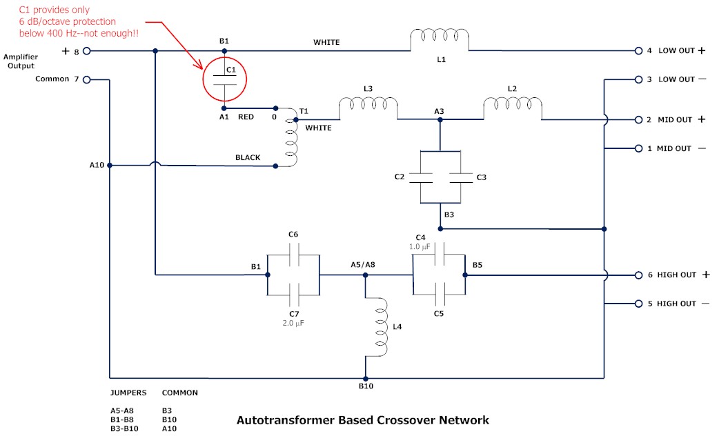
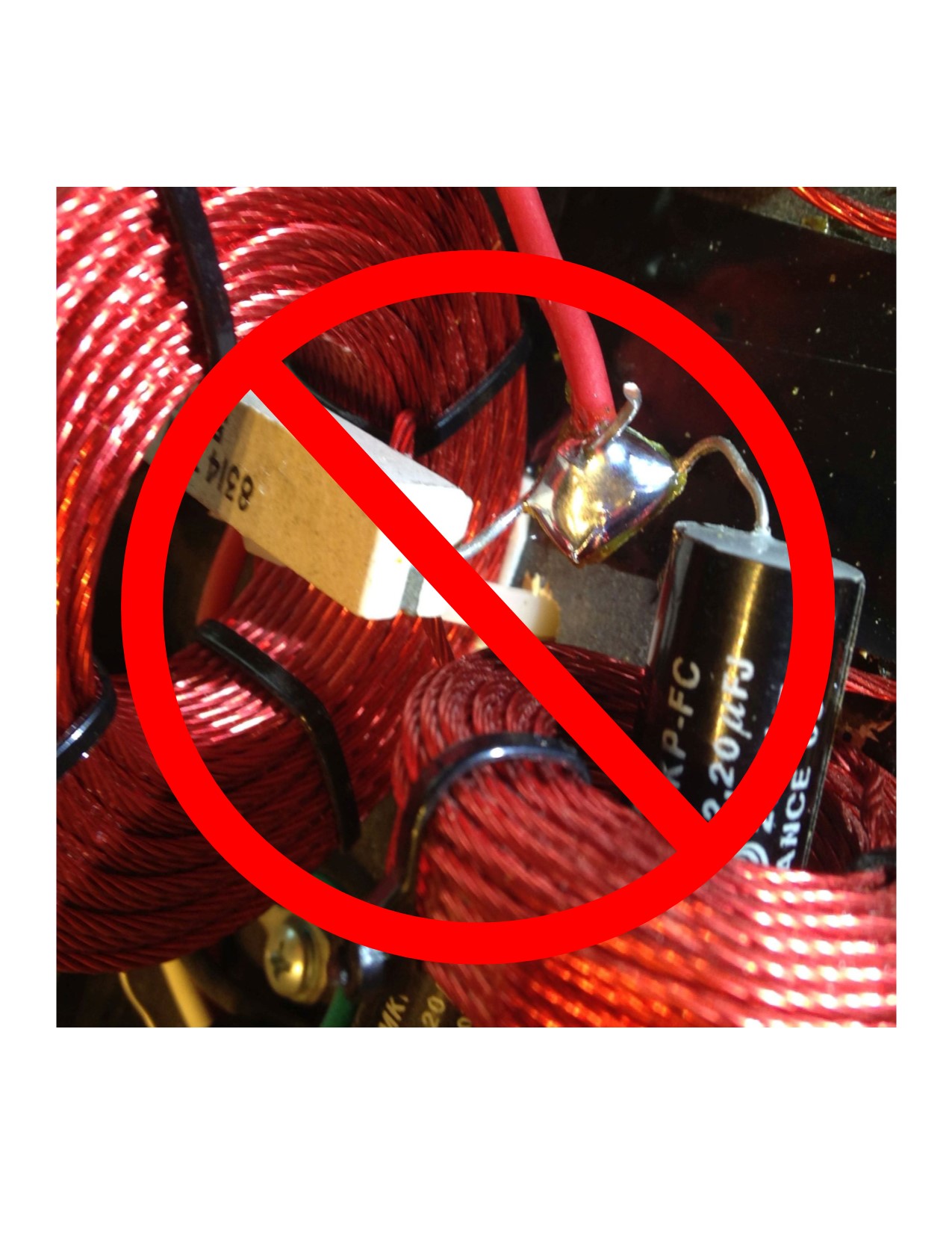
John, First, I wrote: I won't start by criticizing your numerous grammar or spelling errors in your forum post and web site; instead, let's start with how your "top-section baffle insert" is going to sound based upon your published data. Then you wrote: ...from the get-go you made it clear that you were really in this for the fight, nothing more. So from my perspective why bother trying to engage in a dialogue with you. When someone with (or without) a PhD posts misspellings and butchers the King's English, I immediately lower my expectations and hold their credibility suspect. As your company purports to offer "TECHNICAL WRITING AND DOCUMENTATION SERVICES", perhaps you should consider how others view your credibility based upon the above criteria. Up to this point, I'm not "in this for the fight"; just offering helpful advice. The "autotransformer based crossover network" you are hawking is flawed. It is flawed because the Klipsch crossover network from which it was copied is also flawed. The chief culprit is the autotransformer (I'll use the preferred term autoformer from here on); or rather how the autoformer is used in the circuit. The use of an autoformer is an elegant, low-loss way to attenuate the level to, say a squawker driver without the attendant issues of using a fixed resistive pad. For those who may not know, an autoformer is a type of electrical transformer in which the primary and secondary share a single winding. The source (amplifier side) is connected across the ends of the single winding and the load (squawker driver) is connected to one of the winding's end points and a tap somewhere in between. An autoformer can be misused by the unwary or inexperienced crossover network designer who thinks that all you need to do is connect the input of the autoformer to the amplifier side and the squawker driver to the appropriate tap on the load side and, voila, levels are matched! What's not to like? What's not to like is that the amplifier sees a load impedance change with each tap setting. The voltage change (up or down) through an autoformer is proportional to the ratio of the number of turns the source is connected across, to the number of turns the load is connected across. That is, the voltage ratio equals the turns ratio. However, the reflected impedance seen by the amplifier changes as the square of the turns ratio! Here's an example of exactly how the load impedance can swing wildly just by changing taps: Let's take the venerable 3619 autoformer used in the Klipsch AA network and connected to the K55V 16 ohm driver. If you set the 3619 taps to -6 dB (3 and 0), the amplifier doesn't see the K55V as a 16 ohm load; it sees a 64 ohm load! Set the taps to -9 dB (2 and 0) and the load impedance jumps to 127 ohms! If you are running a SET amplifier, good luck driving that load! While I used the Type AA network in my example, your "autoformer based crossover network" suffers from the same impedance swings. The solution? Hint: It's a passive device with axial leads and has a nominal value of 10 ohms. Yep, you just put that "swamping resistor" across the input to your autoformer and those pesky impedance swings are reduced to a load any amplifier can deal with. So, John, for less than a dollar, you can turn your flawed copy, er design, into a more competitive product. But then there's that frequency response anomaly to deal with. Sorry, can't help you there! Lee
-
Naw, it only took a minute or two to recognize a Klipsch knock-off and sketch it. Just so I didn't feel like I was wasting my time, I rotated the tires on my car at the same time. Lee
-
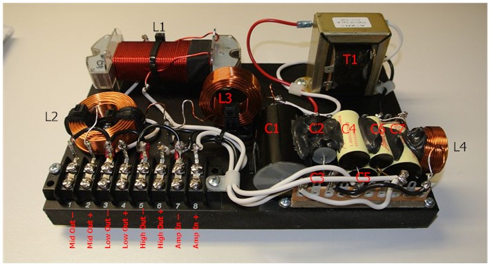
As ad addendum to my previous post, I've labeled the components on John's "Autotransformer Based Crossover Network" so you can more easily follow the schematic. The two "solder rails" to which the capacitors are connected are labeled as A1 thru A10 (at the top of the capacitors) and B1 thru B10. The screw terminal block is labeled 1 thru 8. Lee
-
John, I've posted a schematic of your "autotransformer based crossover network" based upon images on your web site. Feel free to correct it. Better yet, why not post the schematic of the network you use for say the K-77 tweeter? What kind of warranty repair service are you prepared to offer your customer when they fry the voice coil in their B&C DCM50 driver? Your network has a fatal flaw in that you failed to heed B&C's specifications regarding the protection of the driver from excessive low frequency energy. It clearly states that you must use a "12 dB/octave or higher slope high-pass filter." Your network has but a single capacitor (labeled C1 on my schematic) which offers, at best, a 6 dB/octave slope. For those of you in Rio Linda, that means at 200 Hz, the B&C driver will have to absorb twice the power B&C recommends. Hey, he even brags about it by stating, "Low frequencies that would distress the midrange compression driver are attenuated by a single series capacitor..." That statement is disingenuous at best. After reading "We're not adverse (sic) to showing response plots. That's what engineers do, they measure things that guide design changes and decisions.", I thought, great! maybe ol' John will show us electrical plots of his network if I asked him nicely. Well, upon further reading on his web site, he contradicts that "show and tell" attitude by writing, " We do not publish electrical performance of networks because, to the end user, that data is really just bullshit and of no real value. It might look great but how the loudspeaker chain interprets the signals is all that matters." Next time, we'll discuss the "new autotransformer". Lee Lee
-
The plot below is this crossover region in question. As you can see the red plot is the horn without the network and the blue, purple and green are various topologies considered in the design. Also, not shown is how the mid and the tweeter integrate to "smooth" this response. Hmmmm... how is the tweeter's acoustic output gonna fill in the response pothole at 3 kHz? In keeping with your pledge to "...measure everything we sell and provide response plots to you.", how 'bout showing us a frequency response of the combined output of one of your two-way systems with either the Faital or K-77 HF. Quite apparent however is the dip in the response of the system without the network. I do thank you for bringing this to my attention and I will revise the webpage to make this clear. Why did you remove that plot from your website? Are you confirming that the Selenium HM3950 horn + B&C DCM50 driver exhibit the 6-7 dB droop without a network? Regarding the data sheet for the B&C. How is that applicable? My plots have the B&C on a Selenium horn and, as such, the reflections, responses etc. will not be the same. I prefer to see a driver's plane wave tube response; that way we can compare apples to apples without the influence of a horn which may not be optimized for the driver as it appears is the case for the Selenium you chose. And while on the subject of response peaks and dips, anyone that has any experience measuring horns knows that a response within about 10dB is pretty GD good! Well, maybe a 10 dB swing is pretty "GD good" for your stuff, but take a closer look at the B&C DCM50 data sheet. The frequency response is within plus or minus 2.5 dB from say 450 Hz to 6 kHz with their 320 Hz exponential horn; a 5 dB variation. Yours? Plus or minus 5 dB, a 10 dB variation. Lee
-
John, I and some other forum members have no objection to using this venue to "hawk your wares". Having said that, the one hawking their wares is fair game for praise or criticism. I won't start by criticizing your numerous grammar or spelling errors in your forum post and web site; instead let's start with how your "top-section baffle insert" is going to sound based upon your published data. There are two frequency response graphs posted under KLIPSCHORN MIDRANGE, TWEETER AND NETWORK SOLUTIONS on your web site. They are annotated as 8-23-2015 11.34.23 AM and 8-23-2015 11.40.50 AM. Both response curves show a 6-7 dB droop in the measured response between 2 kHz and 4 kHz. What gives? The B&C data sheet for the DCM-50 shows no such droop; instead, the amplitude is seen rising starting at about 2 kHz and has a 4 dB or so peak just below 3 kHz. Granted, the B&C DCM-50 was tested with a 320 Hz exponential horn. So, either the Selenium horn or your network is causing an unacceptable dulling of vocals where our hearing is most sensitive. Lee
-
Looks like there were several versions of the splitter bar for the Klipschorn. I suspect that the La Scala and Belle may have had different configurations as well over the life of their respective productions runs. Attached is a drawing of one of my Klipschorns made after meticulous measurements; ya gotta remove the tailboard and screen material to get up in the guts of the horn! Lee Sideview throat dimensions FINAL.pdf
-
how to protect a vintage Scott faceplate?
Arkytype replied to jimjimbo's topic in Technical/Restorations
Jim, Be careful what you use to clean the panel. Back in the '80s I scored a Denon receiver for a song at a pawn shop. Got it home, whupped out the Formula 409, sprayed the front panel and in mere seconds the lettering dissolved! Nowadays I use Simple Green for most of my cleaning. Lee -
It’s like déjà vu all over again! (apologies to Yogi Berra). I was going thru some old measurements recently and came across the three horn comparison I did lo these many years ago. I posted the color version to make it easier to distinguish each response. BTW, all horns were normalized @ 1 kHz (the vertical line above the “g” in Log). Lee
-
.
-
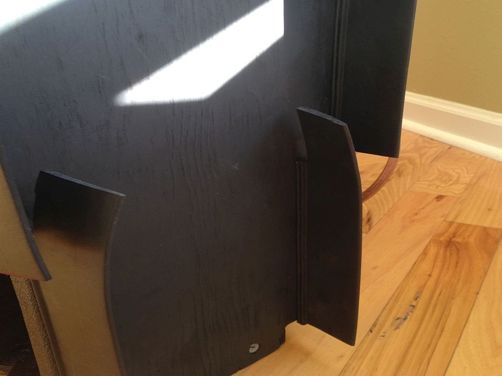
Here's the Klipschorn in the corner showing how all the pieces work to form a good seal.
-
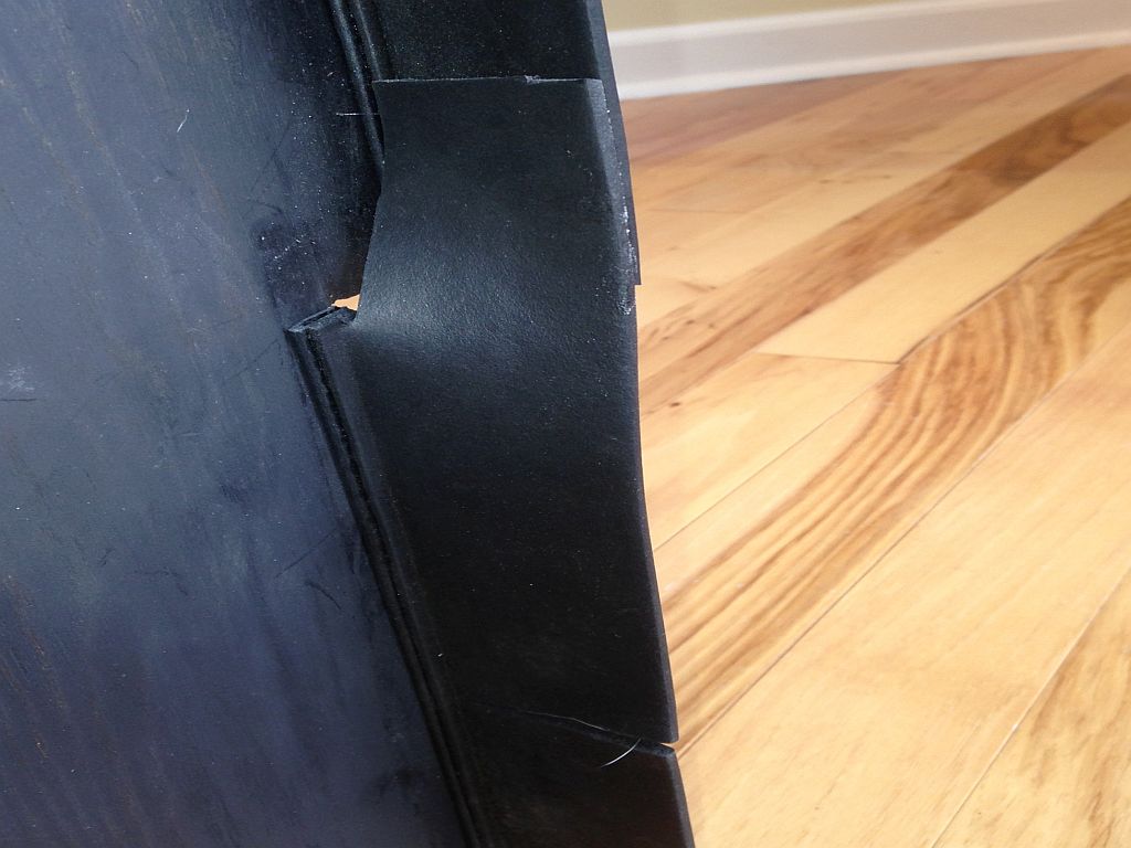
This image shows the flaps of the top and bottom section joined together. Where'd that damn dog hair come from?!
-
Dave wrote,Can't quite figure that out. What are the breaks between the upper and lower flaps for? Looks like the whole thing would stick out from the wall quite a bit. The tailboard has an offset to accommodate most any baseboard molding; so you'll need two lengths of either foam pipe insulation or the product I'm using for each side of the tailboard. I'll attach a few images of my final tweaking. The bottom piece extend upwards into the main tailboard seal and I've cut a notch about 3 1/2" above the floor so the bottom piece snugs up against the 3 1/2" high baseboard. I also ended up gluing the flaps together so that when the Klipschorn is shoved into the corner, there are no "air leaks". In hindsight, I'd probably buy the 3" wide flap.
-
Dave, DOH!! True, it's all about the flux. As the heads wear, the gap widens reducing output and high frequencies. IMHO, ferrite heads were mostly advertising hype; while they didn't wear in the conventional sense, they sure pitted and were not a candidate for re-lapping. I've re-lapped my fair share of audio heads up to one inch (cheap studio owners!). With the proper jig, patience and the correct lapping materials, one can get at least one additional lifetime out of an Ampex, MCI, Otari, duplicator etc. record or playback head. Revox A-77 heads were easy to lap as they had a circular head profile. While this meant they wore out sooner, the heads were in contact with the tape longer than with a "steeper" contour. The result was great HF response and no drop outs when using 1.5 mil tape. Here's one of the jigs I used for 1/4" tape heads. http://www.recordist.com/ampex/docs/repairtips/heads/nortronics.pdf The main issue I encountered with tape stock (Ampex 456) 1/4", 1" & 2" recorded in the early 80's was "sticktion". Apparently the binder would seep/weep to the oxide side of the tape causing the tape to squeal and even stop when played. I never tried the "bake and play" method as the tapes were of limited commercial value. Lee
-
Overall, the book is a qualified good read. Apparently Herr Milner doesn't understand that "sound waves" as he describes them cannot propagate in the vacuum of space. Since no one was around during the so-called Big Bang, his artistic license is a bit over the top. Okay, he's keeping it between the ditches--so far. The primordial sound wave of the big bang is now around 500 million light-years across, reverberating throughout the still-expanding universe. The tone is too faint and low to be heard without the most sensitive equipment, but it’s out there and all around us. The final mix isn't complete, and we don’t know how the record ends. The hum left over from the big bang continues to pump through the speakers of space- time. Describing how magnetic tape recording works, he runs off the road into the ditch by writing, With tape recording, which works on the principle of electromagnetism, there is no physical contact between the inscriber (the recording head) and the medium (the tape). Instead, the current flows past a highly magnetic material, creating patterns of varying magnetic polarity on the tape. As with disc recording, playback means reversing the process. The magnetized tape is passed over a coil, creating changes in magnetic flux. The changes in flux create the electric current that an amplifier converts into watts. Because the current can be represented without physical contact, a tape recording is remarkably durable. Those magnetized patterns will last virtually forever. The main challenge of preserving magnetic tape is not the problem of information loss but rather the breakdown of the tape’s substrate, the actual material it is made of. Huh? Exactly what technology is he describing? Get the Kindle version, it's cheap and if you are interested in the history of recorded sound, this is as good as any account. Lee
-
Guys & Gals, www.rane.com has written four Rane Notes that cover grounding, hum and RF issues when connecting audio gear. I've used these as a pocket reference for many years when solving hum, buzz and RF issues with broadcast and consumer audio products. Take the time to read them and you will solve your issues. Rane Note 110, Sound System Interconnection will probably solve 95% of your issues. If you scroll down to the bottom of each note, you can download the file as a .pdf http://www.rane.com/note110.html http://www.rane.com/note151.html http://www.rane.com/note165.html http://www.rane.com/note166.html I'm not sure if it's covered in any of the notes but providing your gear with a balanced power source and a dedicated ground will almost guarantee a hum, buzz and pop-free audio/video system. I made my own balanced "power supply" using a 2 kw transformer mounted in a NEMA box. http://www.b-p-t.com/what-is-balanced-power.html Lee
-
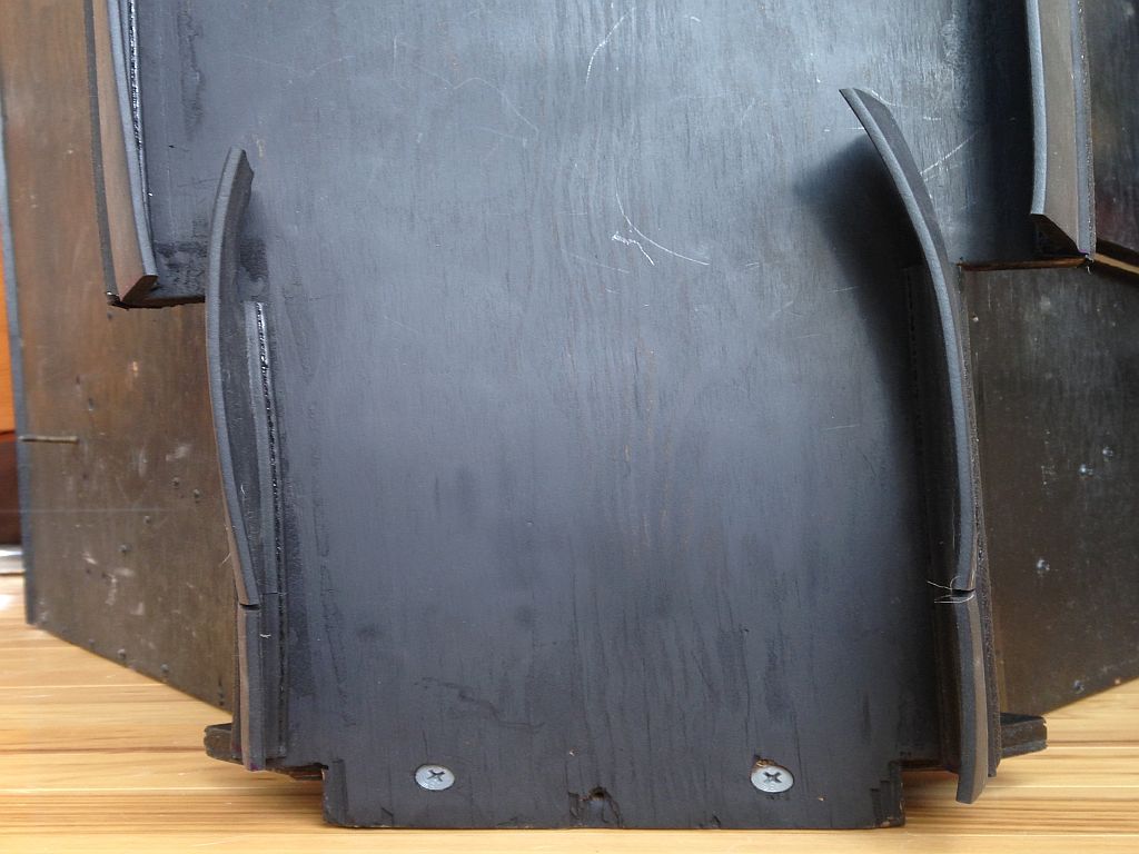
OK, looks like I was diddled by the Dangling Dong of Destiny. After my first post, I got an error message and it went downhill from there. Here's another pix of my tailboard seal showing the lower section. Lee
-
Congratulations on your new Klipschorns. While pipe insulation makes for a quick and dirty bass bin seal, you might want to think about a product that doesn't leave a nasty glue residue and allows the bass bin to get closer to the corner. http://www.mcmaster.com/#catalog/121/3500/=vv459a This is similar to the material Klipsch used to offer as a bass bin sealing kit. The product I use has a 1 3/4" rubber flap but they do offer a 3" (for really out-of-square corners?). For a pair of Klipschorns you will need just over 13 feet. That's enough for both the upper and lower offset tailboard sections. You don't have to order this stuff in the 10-25-50-100-foot lengths, just type in "14" in the "other" box and "1" in the "each" box. Cutting the stuff can be a challenge. I used a jig saw with a fine-toothed metal cutting blade for the vinyl-covered metal core and then scissors for the rubber flap. For the top of the bottom tailboard section, I overlapped the bottom flap about 2" into the top section for a better baseboard seal. If you are content to use foam pipe insulation, I'd recommend the rubber type over the closed-cell foam; you'll get a better seal as the rubber conforms better to out-of-plumb walls. Lee
-
Congratulations on your new Klipschorns. While pipe insulation makes for a quick and dirty bass bin seal, you might want to think about a product that doesn't leave a nasty glue residue and allows the bass bin to get closer to the corner. http://www.mcmaster.com/#catalog/121/3500/=vv459a This is similar to the material Klipsch used to offer as a bass bin sealing kit. The product I use has a 1 3/4" rubber flap but they do offer a 3" (for really out-of-square corners?). For a pair of Klipschorns you will need just over 13 feet. That's enough for both the upper and lower offset tailboard sections. You don't have to order this stuff in the 10-25-50-100-foot lengths, just type in "14" in the "other" box and "1" in the "each" box. Cutting the stuff can be a challenge. I used a jig saw with a fine-toothed metal cutting blade for the vinyl-covered metal core and then scissors for the rubber flap. For the top of the bottom tailboard section, I overlapped the bottom flap about 2" into the top section for a better baseboard seal. If you are content to use foam pipe insulation, I'd recommend the rubber type over the closed-cell foam; you'll get a better seal as the rubber conforms easier to out-of-plumb walls. Lee
-
Sealed the wall seals with 1/2" pipe tubing and let her rip! Klipsch used to offer an add-on kit to seal the Klipschorn bass bin to the corner. It was very similar to this product from McMaster-Carr. http://www.mcmaster.com/#catalog/121/3500/=vv3id7 I bought part number 1120A861 which has a 1 3/4" rubber flap. They also make the same product with a 3" flap. For a pair of Klipschorns you'll need 10'-2" for the upper tail board and 36" for the offset bottom of the tail board. For the lower part, I overlapped the rubber seal so that the upper and lower flaps would work together at the baseboard area. You don't have to order in the 10-25-50-100-foot lengths, just enter your custom footage in "other" and then "1" in the each box. So, for a pair of Klipschorns you'll need 13.16'. Just order 14 feet and you'll be good. Cutting the material to length can be frustrating. I found a jig saw with a fine metal cutting blade works great on the vinyl/metal part and a pair of scissors to cut the rubber seal. If you are content with using pipe insulation, go with the rubber type instead of the closed-cell; it'll conform better to the corner. Lee
-
Buying modified KHorn's - good or bad idea
Arkytype replied to richieb's topic in 2-Channel Home Audio
Steve, I was only pointing out that: What you posted on January 16th is at odds with what you posted in May 2014. Your seeming disdain for any modifications to the Klipsch loudspeakers is a bit hypocritical. You were aware of ALK's networks and were considering a purchase of Al's ES networks. Lee 1 Steven 0 You not only installed non-stock parts in your Klipschorns, you started a topic entitled "My new DeanG networks" July 17, 2014 where you gave them a rave review. While (according to Dean) they are Type AA networks, they are not stock Klipschorn networks. Following the logic of your recent posts, your Klipschorns have "lost the unique-ness (sic) of the brand" and with the network upgrade, could be called Stevehorns. :>) Lee 2 Steven 0 I agree with your statement to richieb re his purchase of Dave's restored Klipschorns, "But they are your ears and it's your money." Since it's the bonus round, we'll leave the score tied at 2 all. Lee