mike stehr
-
Posts
6513 -
Joined
-
Last visited
Content Type
Forums
Events
Gallery
Everything posted by mike stehr
-
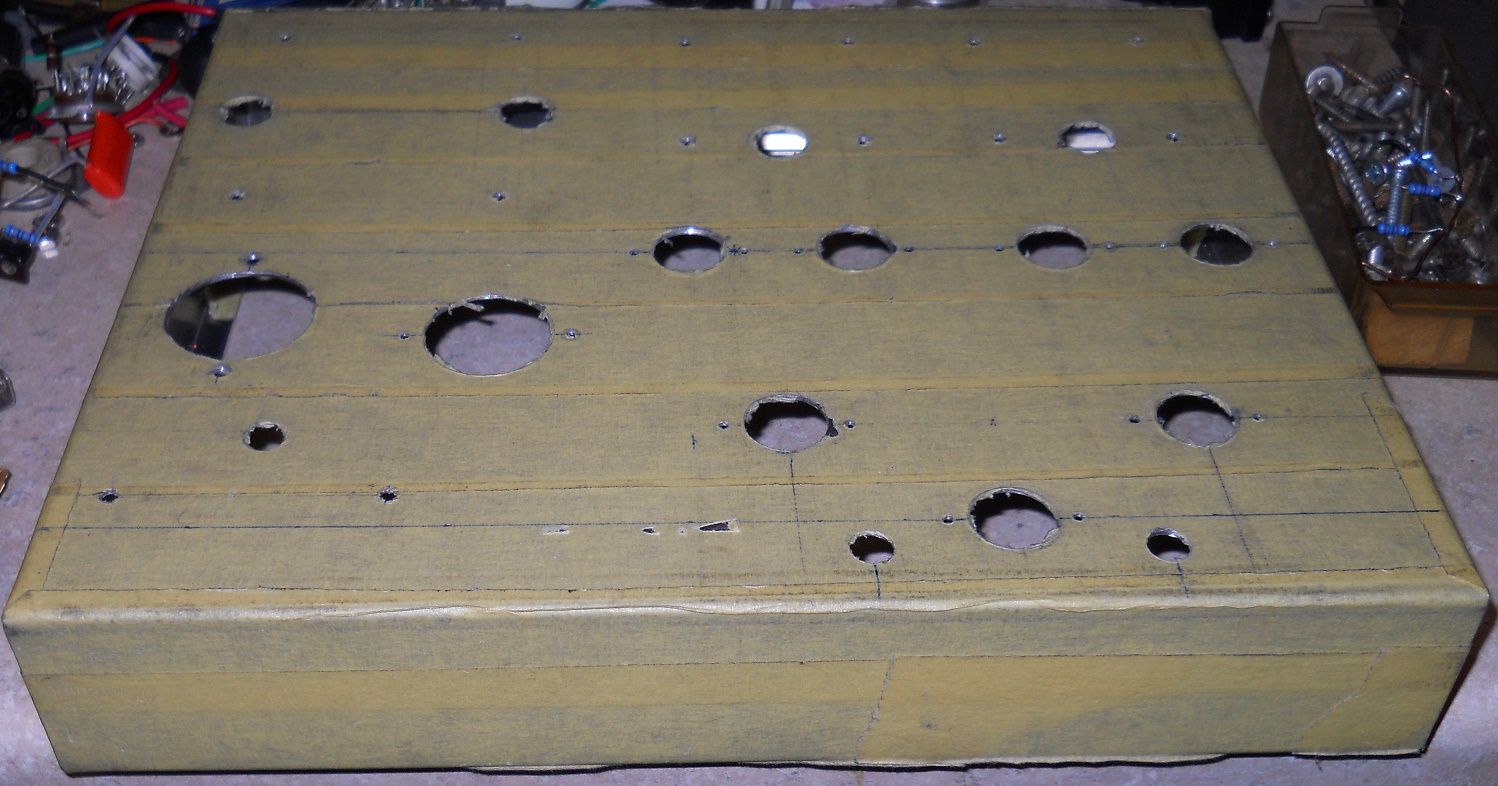
I used a stepped bit. I have a smaller one, and a larger one that maxes out at 1-3/8". How often will one need a 1-3/8" chassis punch/die? They can leave a nasty burr on the bottom of the piece being drilled. But if one can flip the piece over and get at the burred side, one can use the bit to de-burr the hole. I think the key is to keep the piece being drilled as anchored as possible along with the press. (I have a cheap tabletop) The bits are aggressive, especially larger one.
-
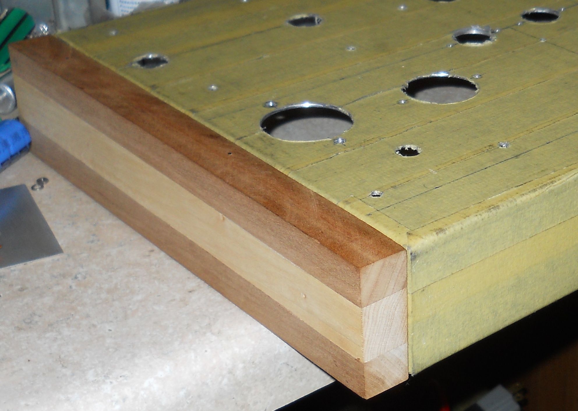
A few more holes...

-
When you mentioned 10 watt mono amplifiers, I thought you were referring to what I have. Those are parallel push-pull 6V6, (142AA?) each at 20 watts.
-
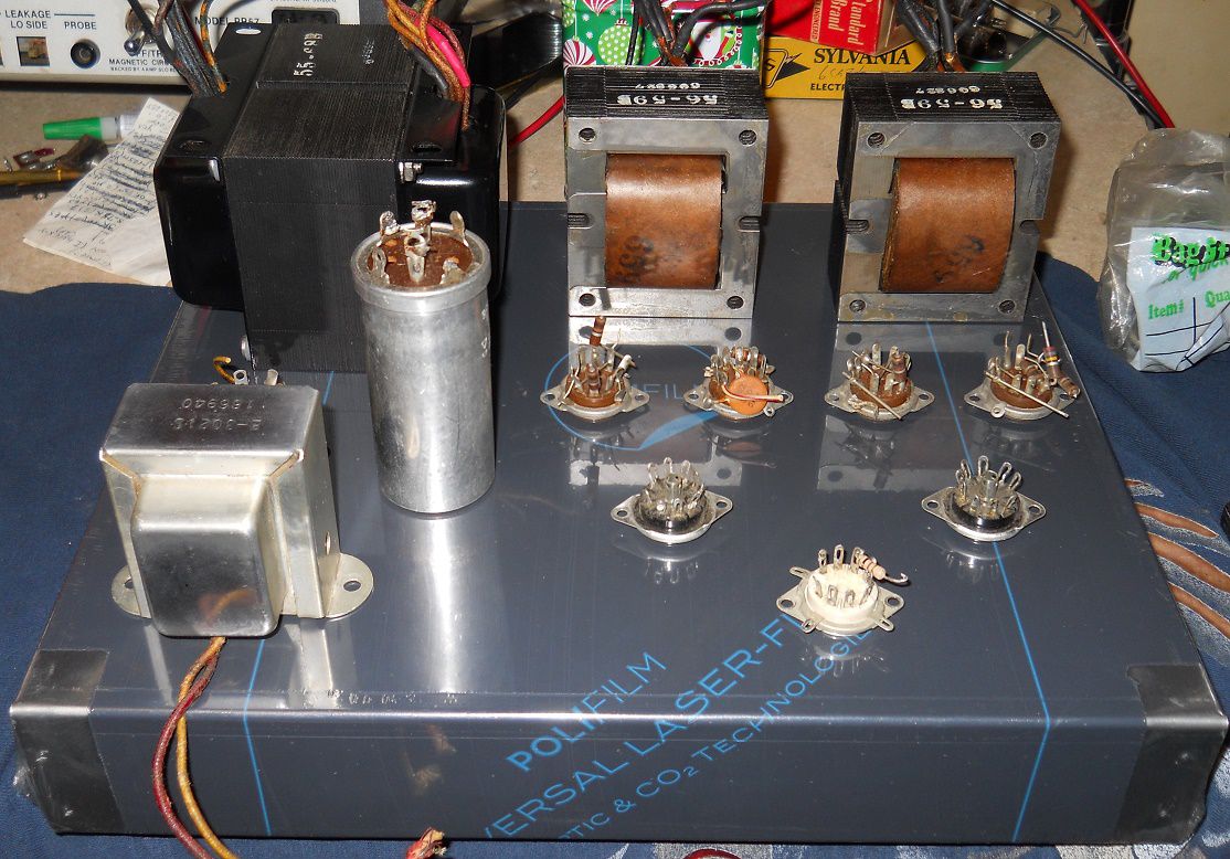
Do they look similar to this one?
-
Breadboarding with a DC tube power supply is one way to build and test tube amplifier circuits. One is limited by voltage/current output of the supply, however.
-
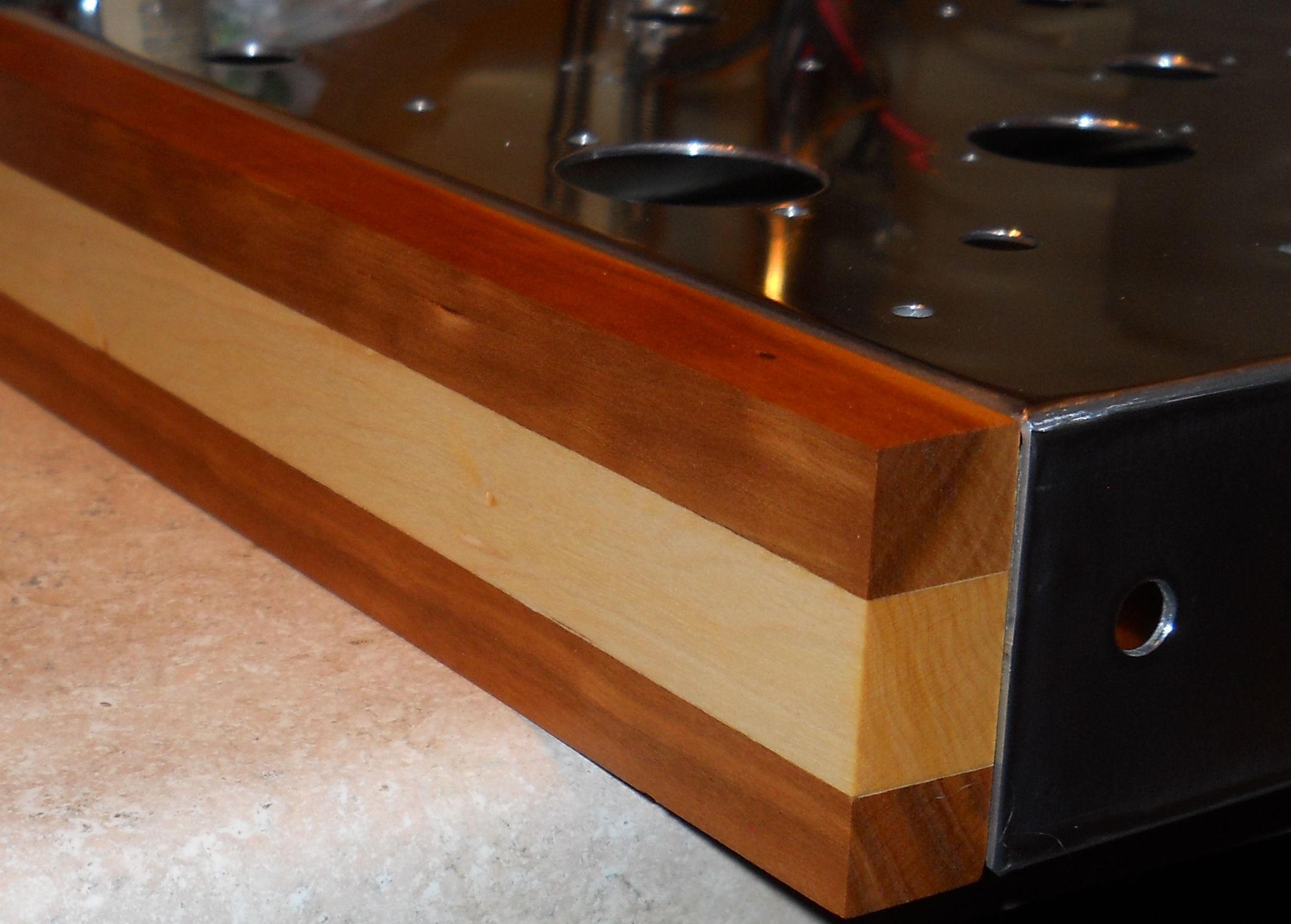
A different approach...
-
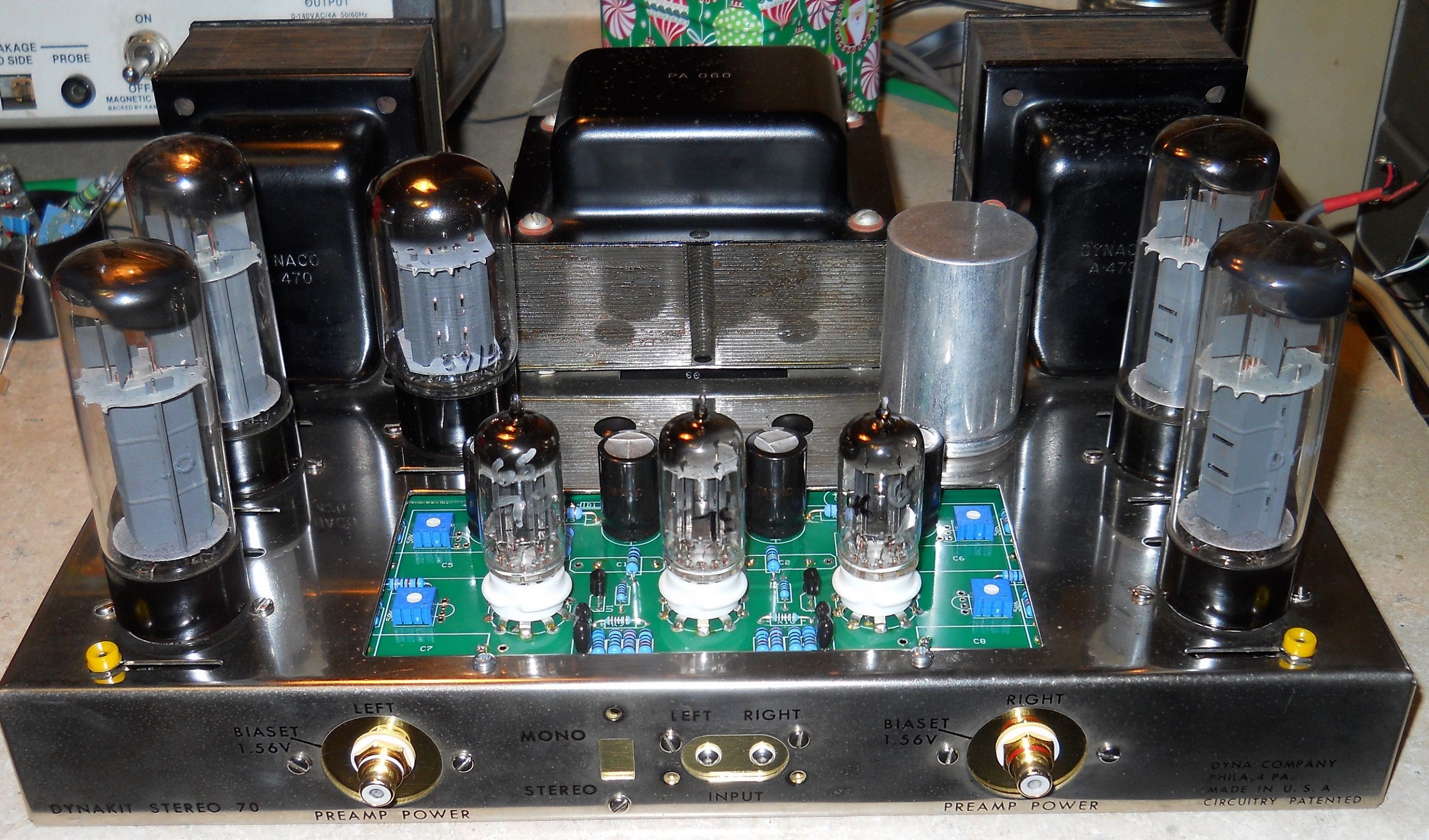
Working on this for a friend... Old school Dynaco ST-70, with cloth leaded OPTs, what appear to be the original EL-34 output tubes, and the VTA version II PCB.
-
I had some Suntan branded trim pots once...they were garbage. Go with Bourns.
-
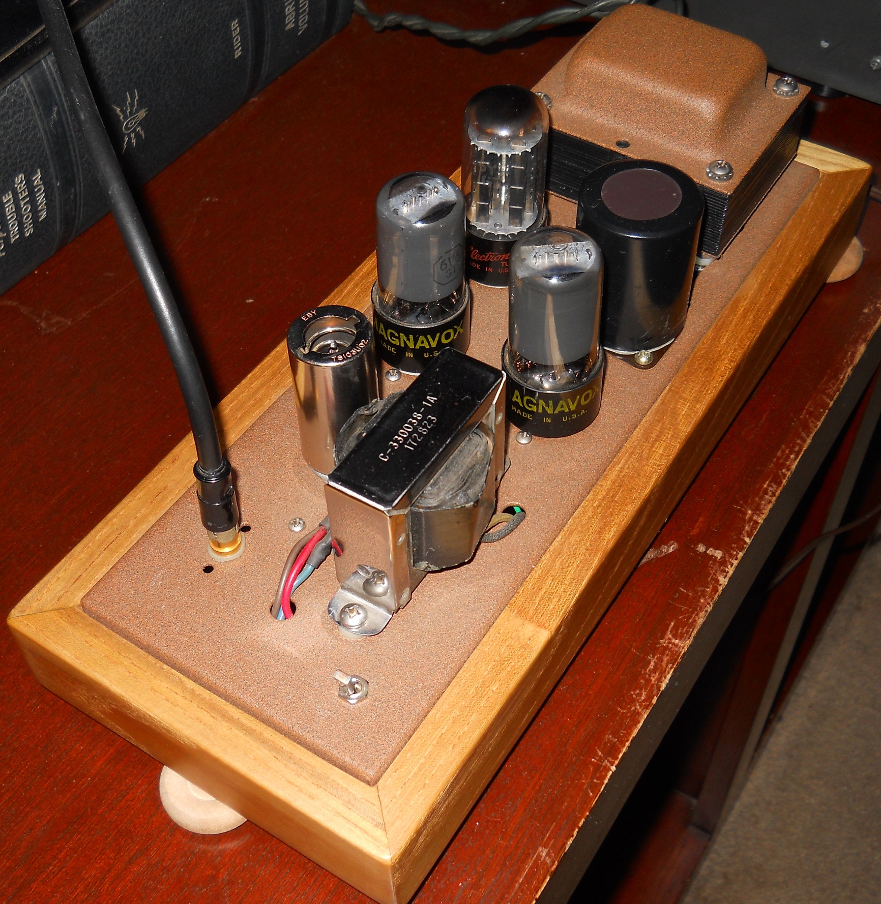
Magnavox 6V6 PP console amps.
-
Nice!
-
-
-
Should there be a poll in the Garage Section?
mike stehr replied to Zen Traveler's topic in Garage Sale
Let's have a poll on that...will he return or not... -
I went ahead and checked out both channels on the oscilloscope using the 5R4 rectifier. Before I connected the signal generator, I went ahead to see how the output channel A and B looked on the scope without a signal. With the inputs shorted. Channel A has a nice noisy looking ripple waveform going. Channel B has the same ripple waveform with a nice spike in the middle...almost like a square wave sort of spike with a sharp slope. Too bad I can't recall if the slope was leading or lagging...dur... I didn't bother to connect the signal generator. It would be too difficult to see the waveform through the ripple. Indeed. Even my local audio mentor brought it up. To be honest, I have no problems with the Pilot schematic/circuit. But I am not fond of how the circuit is laid out in too small of a chassis, with a weird Pi filter that parks B+ for the OPTs at the screen pin of one output tube of the push-pull pair. I measure the screen pins, and I have more voltage on the screens than the plates. (The two tubes without the 270-ohm screen resistors) Or the fact everything is grounded to the sockets, and many chassis' grounds as well. I suppose I could connect the amplifier to my bench speakers to hear how noisy it is or figure out why. But it this point, I'm really pondering buying a bud/hammond aluminum chassis of larger dimensions. Then I would have room to lay-out/wire the circuit my way. With a choke loaded supply, or CLC to drop B+ with a bit better regulation. Before I do that, I best make sure these output transformers are up to snuff...I don't like that spike... I'll determine the primary impedance and run a simulated primary resistance with a resistor and an 8-ohm load resistor. Then run a signal generator into the primary and monitor the 8-ohm secondary with a scope using sine and square waves. Monitor for any anomalies between each output transformer, and if the characteristics match up for both pair. Thanks for the help, Mike
-
Okay, then that confirms my math for determining plate current from cathode voltage. You must have used the Sam's schematic with the plate voltage value. The original Pilot SA-232 schematic shows 320 volts on the plates. I have no idea why there is voltage differences between the schematics. The Pilot schematic mentions; "measure at 117VAC". But I'm sort of curious if maybe they measured at 115VAC? The Sam's schematic falls more in line with voltages stated measured at 117VAC from what I come up with. If a guy looks at the values for both Pilot and Sam's schematics, and determine total plate current from cathode voltage, they both just hammer on the 6BQ5s, if my math is right... You mention the amplifier (sounds?), or (operates?) best with the tubes at near max dissipation? I can just imagine back in 1960... "This amplifier sounds wonderful for a few months, and then the tubes glow red." Seems kinda rich even back when readily available 6BQ5/EL84 were 3-4 bucks a pop. Using a combination variac/isolation transformer, with 117VAC in, I get 360 volts B+ on the first cap, with 335 or so on the plates, and 12 volts on the cathodes. My numbers for dissipation of the output tubes are the same as you mentioned. I swapped in 150 cathode resistors, it raised the plate voltage 3-4 volts, and lowered the cathode voltage about a volt. It still comes out around 13-14 watts per tube. Keep in mind I'm trying to average things out, because I'm not using matched output tubes. I don't really want to cook my good 6BQ5s, so I'm using a junk quad to get going. They match emission-wise on a tester, but that's pointless in circuit. If I sub in a 5R4 rectifier, I get 312 on the first cap, around 285-290 on the plates, and around 11 volts on the cathodes. The drops the dissipation number down to 10 watts for each tube. Roughly 85% of the total 12-watt dissipation rating I'm guessing. It doesn't drop much voltage on the driver and phase inverter tubes, so it may actually pass a signal.
-
I know you mention a long time ago, but do you recall having to re-bias the amplifier's output tubes at a lower dissipation rating?
-
-
What is the best woofer match for the Cornscala?
mike stehr replied to mopardave's topic in Technical/Restorations
MoCorn CornPar Klipschmouth Dodgewall Chryswall -
What is the best woofer match for the Cornscala?
mike stehr replied to mopardave's topic in Technical/Restorations
I'd call it for what is; Crites Style D two-way...single cab or split cab. I listened to the two-way split style D. That convinced me enough to go through the trouble to put all the components for Crites Style D into a Jensen Concerto "ultra-flex" cabinets. -
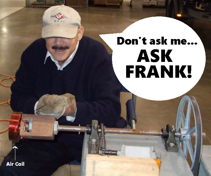
I had no clue about this Frank person, so I did a search and found a youtube video with regard to himself and Carver products. Right off he mentions he doesn't want to throw out any technical fluff, and then starts to throw out a bunch of fluff like a snake oil peddler. Then proceeds to wax on about ole Bob like he invented human hearing or some such. I made it about a minute through the video before cringe factor set in.
-
Ouch Carver Crimson 275 Measurements | Audio Science Review (ASR) Forum
-
My 2A3 amp started out using those pseudo 300B solid plate 2.5-volt TJ voice of music balloon globes. I suppose they were used so one could use direct heating; a bit easier to pull off than 5.0 volts AC. The output transformers are Scholl if I recall, with a 3.6K primary using 4- and 8-ohm taps. The amplifier outlived the TJ globes, so I swapped to 2A3. I've used Sovtek 2A3 tubes for couple few years and still have them. Still have the TJs. Used Sylvania 5930/2A3W. Ugly, but tough... Currently I'm using GE 2A3s. H plate or some such. It's a good sounding amplifier to my ears...
-
...change of Gender?
-
Looks like you're using 6EA7 instead of 6DN7?