robotc
-
Posts
22 -
Joined
-
Last visited
Content Type
Forums
Events
Gallery
Everything posted by robotc
-
Your crossover looks great. I am really interested to hear how you find the sound from the new version. The resonance at 200Hz was definitely due to the rubber feet. At that frequency the whole enclosure was vibrating strongly. I am not sure if it would be audible when listening to music because the peak was so narrow. Removing the rubber feet went a fair way to reducing the resonance. I can post the measurements if you are interested. Are you making any measurements of your speakers? Robert
-
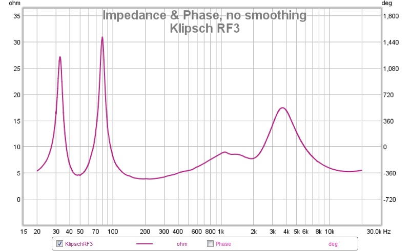
I haven't visited the forum for a while and just found your post. The only resonance that showed on the impedance plot was around 200Hz. I did a bit of investigation and found that this was the resonance of the whole enclosure vibrating on the rubber feet. I braced and damped the enclosures but I couldn't see any differences in the before and after impedance plots. However the changes made a big difference subjectively. The tweeter attenuation on the plot I posted was 10dB. This gave the flattest measured response but I felt subjectively this was too much Robert
-
RF3 Impedance

-
Discontinued Klipsch speaker specs no longer available
robotc replied to robotc's topic in Technical/Restorations
You're right. Klipsch have removed the specs from the Aus site and replaced them with the pictures and general description from the US site. Why have Klipsch done this??? What's the point?? -
CORRECTION TO CIRCUIT I was hoping this wouldn't happen but it did The polarity of the tweeter was incorrectly marked on the schematic. Here is the correct version klipsch RF3 mod.xover revised.pdf
-
The resistance is not critical. I modeled the crossover with the total resistance of the 1.0mH inductor plus resistor as 8.2R but an ohm difference either way shouldn't make much difference. The series LCR is there to level out the tweeter impedance at resonance. The load is 4ohms across the whole frequency range. Robert
-
Chris A's suggested mod for 400/401 horns is awesome
robotc replied to jwgorman's topic in Technical/Restorations
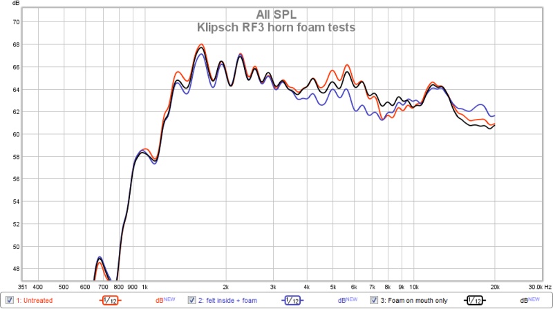
I did some testing of foam in the horn of my RF3 speakers a while back. The results I got might not apply to the horns you are modding but the results might interest you. I decided not to use foam inside the horn because I thought it might affect the geometry too much. Instead I stuck felt on the surface covering about half the depth of the horn. I also stuck a strip of open cell foam around the outside of the mouth. The effect on the frequency response is shown in the attached graphs. The measurements are at 80cm with no crossover attached. I didn't like the effect on the sound produced by the felt but I have stuck with the foam around the horn mouth. Robert
-
Finally here is my crossover design for the RF3. I think I will start a new topic sometime and explain more about what I have done to arrive at this circuit. But for now here it is for anyone who wants to try it. The effect of the notch filter on the woofer is easily heard if you disconnect the tweeter and play music through the woofers only with and without the notch filter. The tweeter crossover was altered to account for the removal of the treble output of the woofers by the notch filter. I have not settled on the amount of attenuation of the tweeter. At the moment I think 6dB is about right. Robert Edit: The schematic had the polarity of the tweeter incorrectly marked. See later post for revised version
-
Hi Guys I haven't forgotten you. I'm back home and will post the xover in a couple of hours time . A few things to check- I want to make sure I post the correct version Robert
-
I have just noticed that the US Klipsch web site no longer lists the detailed specs of discontinued models. There is just a brief description and pictures and then a link to the current models. If anyone is looking for specs, the Australian Klipsch web site currently has the more detailed specs available. Just type the model in the search box on the home page Robert
-
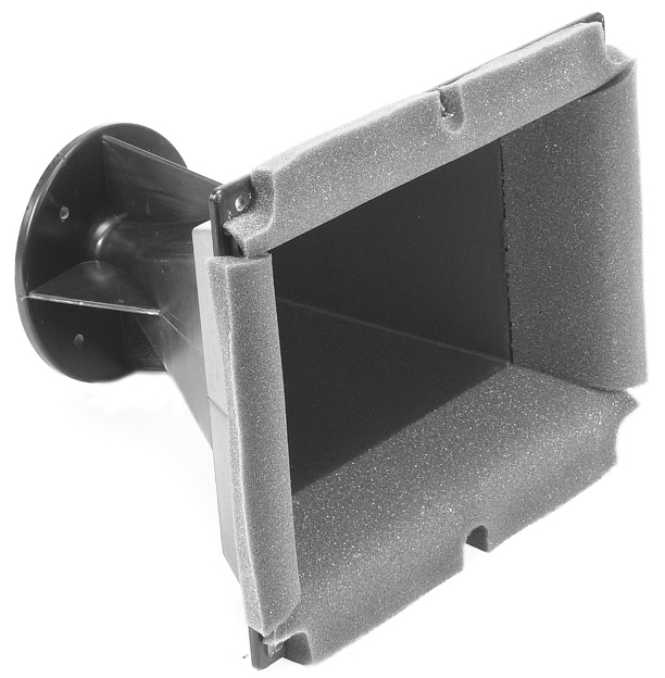
Yes it is open cell foam.The Peavey horn looks like the horn is molded so the foam sits flush with the inside surface and wraps around the mouth edge. I tried felt inside the RF3 horn because i figured thick foam inside would change the horn dimension but to me it didn't sound right. A foam strip around the mouth did improve the sound. Robert
-
I tried inside the horn (see photo of a Peavey horn) but I didn't like what it did to the sound. I ended up with a strip around the edge of the horn on the outside sounding the best to me - but the effect was not dramatic. Robert
-
One mod you might like to try is placing some foam around the mouth of the horn just on its outer edge. I ended up using 10mm open cell sealing strip. The foam seems to level out the response above 5kHz. I found the effect on the level is measurable. In my opinion the effect on the sound is not massive but it does make it a little clearer and more focused. There is an interesting article about this by Jeff Poth called Foaming at the mouth You might want to try some foam on your horns (its cheap) and see if you can hear a difference. Robert
-
Sorry I cant help you with the RC-3 and RS-3 crossovers. I bought my speakers with an RC-3 center but I sold it because I only listen to 2 channel music. I'm not into home theater so the changes I made have been for music not movies. Robert
-
I have never heard a pair of RF7's but I would guess they are better speakers. I paid around $400 for my RF3's about ten years ago. At the moment in Australia I could buy a new pair of RF7's for US$7400 (discounted!!) or a good second hand pair for around US$5000. I can upgrade my speakers with new parts for a fraction of that.
-
Yes I do. BUT... I am currently away from home and wont be back until 22 December. I have my laptop with all the measurements but I don't have the papers with the final crossover schematic. I would prefer to wait until I am home again rather than try to remember and get it wrong. I am happy to post it then. Depends what you mean by modified. The crossover I have is a complete new design. See my previous post. Robert
-
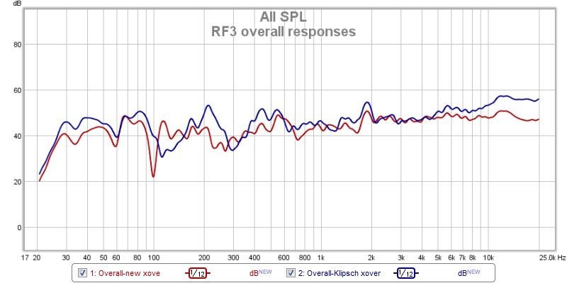
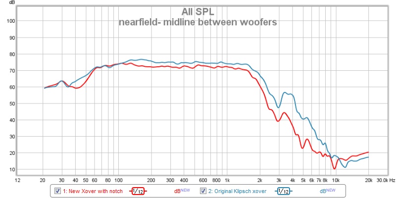
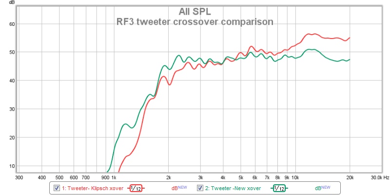
Hi Rob I have designed a new crossover from scratch. Using the frequency and impedance files I measured using REW, I used a program called Passive Crossover Designer to produce designs that I constructed, then measured and listened to. After a lot of trials I came to my final design The crossover is still a temporary version mounted on a matrix board. If you wanted to try just the notch filter it is a parallel LCR combination in series with the woofers, so you could just put it between the existing crossover and the woofers The Klipsch tweeter response through the filter is tilted upwards towards the higher frequencies. I don't know why Klipsch did this but it may be they reduced the level from 2kHz to 5kHz to compensate for the extra output from the woofers cone breakup. When I used the notch filter I felt the tweeter needed more output around 2kHz to 5kHz. The Klipsch xover also has a rising output right up to 20kHz. Again I am not sure why but it might be to increase the off-axis level of the horn. I decided to level out the response. The measurements I posted were taken at one meter from the speakers (farfield). This means the room has a drastic effect on the measured low frequency response. I have attached a plot showing the nearfield response taken a few mm from the front baffle midway between the woofers. As you can see the response is much smoother however the measurements around the crossover frequency are not so accurate. The dip around 40Hz is the region where the port fills in the response. With the notch filter the cone breakup is still there but much reduced I have also attached a plot showing the overall frequency response for the Klipsch xover and my version. Farfield measurement so the low frequencies are all over the place. The only thing I have not sorted is the amount I need to reduce the level of the tweeter. It needs a few dB attenuation.
-
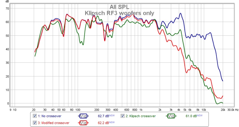
Hi everyone I just found this thread and thought I could add something to it. I have owned a pair of RF3's for about 10 years and love a lot about the way they sound but I have come to realise over time that on some types of music they can sound harsh and tiring. Aluminium cone woofers, as used in the RF3's, are prone to breakup resonances which I believe lead to the harshness I have made a lot of measurements and tested a lot of different crossover variations to try to achieve a less tiring sound but still retain the life and realism of the original design. The attached plots show the frequency response of the RF3 woofers, measured on the axis of the top woofer at 1m. The cone breakup around 4.2kHz is clearly visible on the plot with no crossover. The measurement with the Klipsch crossover shows that the resonance peak is still present and the output at 4.2kHz is only about 5dB down from the output at lower frequencies. The third plot shows the woofer output with a modified crossover which includes a notch filter. The level at 4.2kHz is now about 20dB down and much less audible.(Modifying the woofer filter in this way means the tweeter crossover must also be modified) Regards Robert
-
Klipsch RF7 (old version) crossover modification
robotc replied to Yasnyi Sokol's topic in Technical/Restorations
Hi Alexander It is interesting to see the original RF7 tweeter crossover response modeled. This is similar to the response of the RF3. My theory is that the Klipsch design engineers deliberately sloped the tweeter response to compensate for the extra energy produced by the woofer cone breakup around 3-5kHz. Once you remove this breakup with a notch filter i believe you need to level out the tweeter response. I have attached modeling of the original RF3 tweeter response( which also has a rising response to higher frequency) and my modified crossover which is 3rd order with a Zobel and an LCR to give a virtually flat impedance. Original New Robert
-
Klipsch RF7 (old version) crossover modification
robotc replied to Yasnyi Sokol's topic in Technical/Restorations
I am not sure about the wisdom of using a first order crossover here. The output at the tweeter resonance (around 1kHz) looks to be only about 10dB down on the output at 6kHz. Are you modelling the crossovers you have designed? Using Passive Crossover Designer I modeled the electrical response of the crossover you posted in post #17 . The response is into 8ohm. This is not the whole story because you need the frequency response and the impedance of the speaker driver to model the sound output. However the shape of the crossover electrical response might give a clue as to why there is too much output at the high frequency end.
-
Klipsch RF7 (old version) crossover modification
robotc replied to Yasnyi Sokol's topic in Technical/Restorations
Hi Alexander I was really interested to read about your measurements and modification to the RF-7 crossover. You have done a lot of work testing and preparing the information you have posted. Congratulations. I have been making similar measurements and modifications on my RF-3 speakers which, like the RF7, have twin aluminium cone woofers and a tractrix horn tweeter (speaker drivers are different models of course) Like the RF7, the RF3 metal cone woofers have a large resonance ( at around 3-5kHz), which can only be reduced significantly with a notch filter similar to the one you used. The difference with the resonance reduced in level is clearly audible. I believe this extra (unwanted ) sound energy around 3-5kHz is a big part of what gives the speakers the ‘klipsch sound’ which can be very impressive and realistic with some instruments (eg saxophone) but which can become unpleasant and harsh when listening to music, especially at high levels. Robert -
Hi Check out this link to the Klipsch forum. It lists a lot of Klipsch crossover schematics including the RF7.