


mboxler
-
Posts
574 -
Joined
-
Last visited
Content Type
Forums
Events
Gallery
Posts posted by mboxler
-
-
45 minutes ago, babadono said:
Mike, how is that figured? I just plugged in the 4mH and 100 uF into the basic equation. Do you have to take voicecoil L into equation as well?
Yes you do. One of the few things ALK stated that I agree with is that the K33 looks like a 1mh inductor with a DCR of 6 ohms @400hz.
What equation are you using? Here's an LTSpice simulation of an AK-3 woofer low pass as well as a REW voltage plot.
Mike

-
12 hours ago, babadono said:
Looks like the Fc of the lowpass filter is about 251 Hz.
If you are referring to the electrical cutoff, it's closer to 350hz on an AK3 Klipschorn. I imagine it's still close to that on a La Scala, but I'll measure the impedance of a K33 mounted in a La Scala later today to be sure.
Mike
-
On 1/29/2024 at 9:36 AM, Invidiosulus said:
i still have a pair of K-400 horns sitting around here somewhere.
Once the weather gets nice I plan on getting some on and off axis measurements with the K-55-V just to satisfy my curiosity.
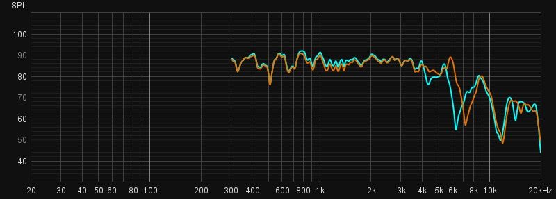
As is usually the case, the truth tends to be somewhere in the middle. To satisfy my curiosity, I ordered a pair of Altas PD-5VH's. Below are plots of a new PD-5VH (Blue) and an old K55V push pin (Orange). Both measurements start at 300hz on a K-400 horn with no filter. I'll let you decide the frequency responses of each driver. Again, the Altas driver is brand new. I don't know if the FR will change over time.
Mike
-
 4
4
-
-
15 hours ago, Mycuff said:
I did not mean to roll a grenade into this forum. Holy cow what just happened?
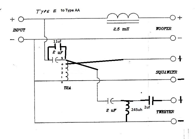
After all that drama, I forgot to answer the other part of your question...
1) Either add a 10uf to 12uf capacitor in parallel with the main high pass capacitor, or replace it with a 12uf to 14uf.
2) Move the K55V to tap 4 of the T2A.
3) Move the K77M to tap 5 of the T2A.
4) Change the K55V and K77M polarities back to normal.
5) On the tweeter filter, add a parallel 245uf inductor and second 2uf capacitor.
Please excuse my poor illustration 😀
-
3
-
 1
1
-
-
28 minutes ago, OO1 said:
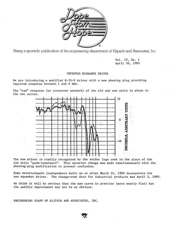
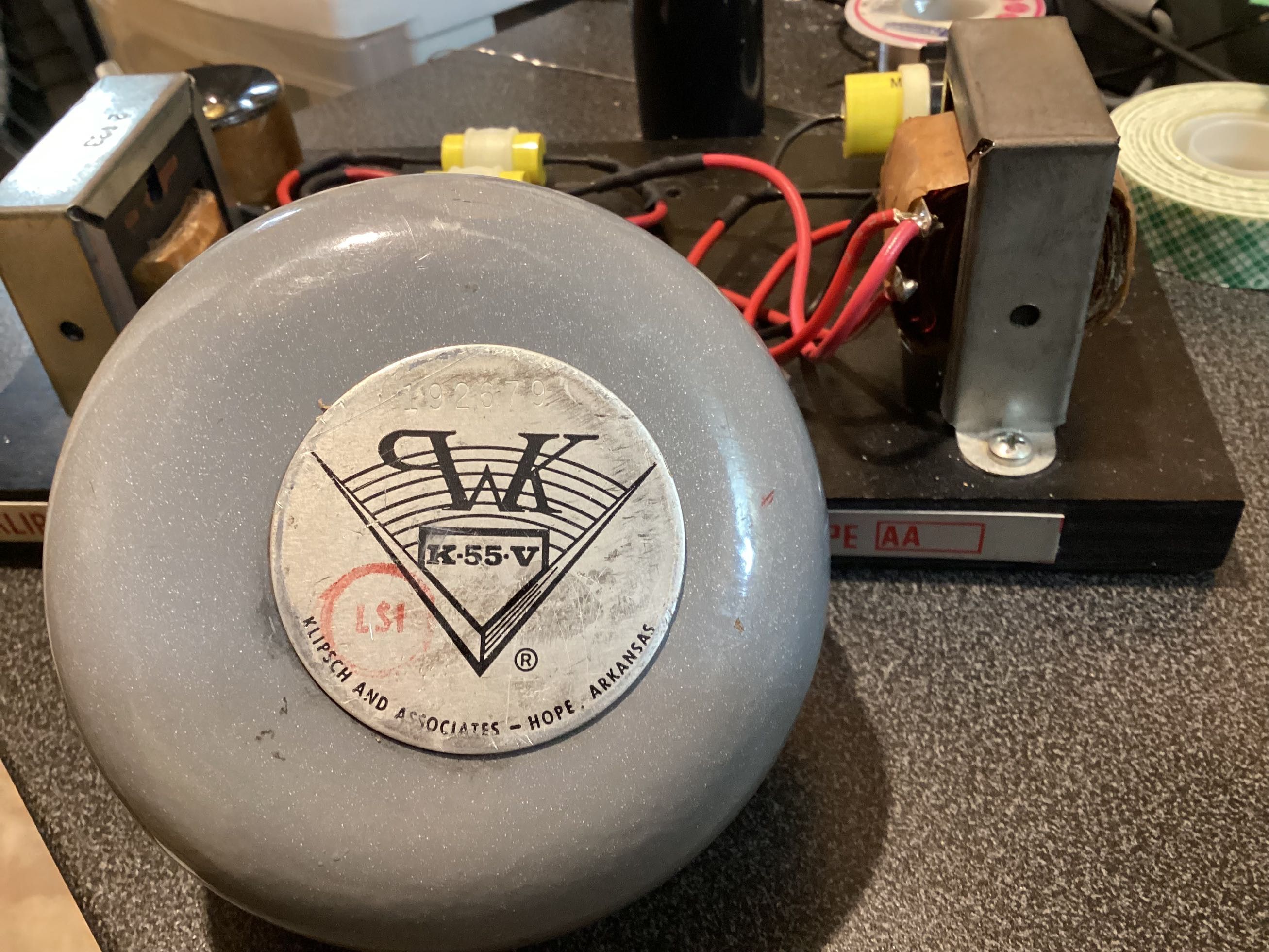
the specs of the 70's -80's K-55V with the original Atlas diaphragm indicated that it extended to 6KHz whether single or dual phase plug and so does the K-55M , but the K-55M was hotter , and we all know that the newer 2001 K-55X , PD5VH including the newer D-20GB diaphragms only extend to 4100Hz .
It may extend to 6khz, but not gracefully. Or am I missing something???
-
1
-
-
I may be a party of one, but I find the AA with those drivers unlistenable. To start with, the K55M's FR extends flat to 6khz compared to the K55V, which starts fluctuating around 4.5khz. I believe that's a big reason why the AL has the steep 6khz high pass to the K77M.
The AA's tweeter filter is really closer to a 5khz high pass, and somewhat equalized to blend with the K55V. With the AA, there is an overlap from around 4.5khz to 6khz that I found annoying. I know this because I built a pair of AA's and tested them on my AK-2 Khorns.
Again, I may be alone on this, but since you asked 😎
Mike
-
2
-
-
7 minutes ago, Mycuff said:
I have an AL and its bad. Looking at options now. One being an E to AA conversion I saw. Curious on people’s thoughts on that.
I assume you have the K55M and K77M? For my own information, does the K77M mount flush with the back or the front of the motor board?
-
2
-
-
The 4uf capacitor may be too small to work properly with this last change but as always let your ears be the judge.
-
Yes leave the tweeter on tap 5. Squawker to tap 4. Unfortunately if you leave the back off you’ll loose some base. I’d put the back on with only 4-6 screws to ease the process.
-
1
-
-
57 minutes ago, ronajon said:
thank you. it took me some time to figure out the layout of the scheme from @mboxler since i'm a total noob on electronics, but finally got there.
only did one for A/B testing purposes, my first impression was that the overall sound level seemed a little lower?
i'm not sure if that's correct, because from the thread i read that the voltage for the CT125 should raise by 3.35 db (is that decibel ?) and the squawker should drop with 1db
So to my understanding the overall sound should be louder, or am i totally wrong here ?
We are all noobs one way or another.
Yes, db is decibel.
Perhaps the squawker dropped by more than I thought. The only other thing would be to move the squawker from tap 3 to tap 4 as well.
Sorry. If I had Cornwall's I would try this myself before suggesting the changes. I know it's a pain to remove the back.
-
1 hour ago, ronajon said:
the step up from the plastic piezo tweeters to the CT125 from @KT88 was already a huge one.
The sound with these CT125 is warmer and smoother.
i'm sure willing to mod the CT-125, but not sure how to "move the tweeter filter from tap 4 to tap 5 " ?
as this is not my topic and i don't want to hijack it with my questions, i'll move this to my own thread about the Cornwalls i recently purchased. Feel free to continue there on modifying the CT125's i've got .
On the Type B crossover, the tweeter filter is connected to tap 4 (-3.35db, dotted line). Simply desolder that wire (which is connected to the 2uf tweeter capacitor), and solder it to tap 5 (-0db, bold line).
-
2
-
-
1 hour ago, KT88 said:
That was exactly the same thought I had. I sold a pair of CT125s to @ronajon for his Cornwall 1. He likes them, but it would be nice if the SPL was a bit more balanced. They were too quiet for my LaScala but for his Cornwall they should have some reserves as the efficiency of the Cornwall is a bit lower. What does he need to do to get the SPL of the CT125 to match his Cornwall exactly?
Moving the tweeter filter from tap 4 to tap 5 will increase the CT-125 voltage by 3.35db. It also drops the K-55 voltage by around 1db. I don't have a Cornwall to measure the actual SPL changes but it's an easy mod to try.
-
2
-
-
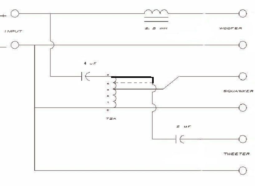
3 hours ago, Erivera1990 said:
Just got a pair of Klipschorns!
I have a few questions in regards of the internal wiring, mids, tweeters and crossovers.
- Is 16 awg good enough for rewiring my speakers? Or should I go with something like 14 or 12 awg? (The current ones aren't in good shape)
- For my mids (k55m) and tweeters (CT125), is there a rebuild kit? Should I take them apart to clean it or should I leave them alone? When I took everything apart it was pretty dusty inside.
- I currently have Crites A Crossovers, could I eventually upgrade the same crossover to an AA one?
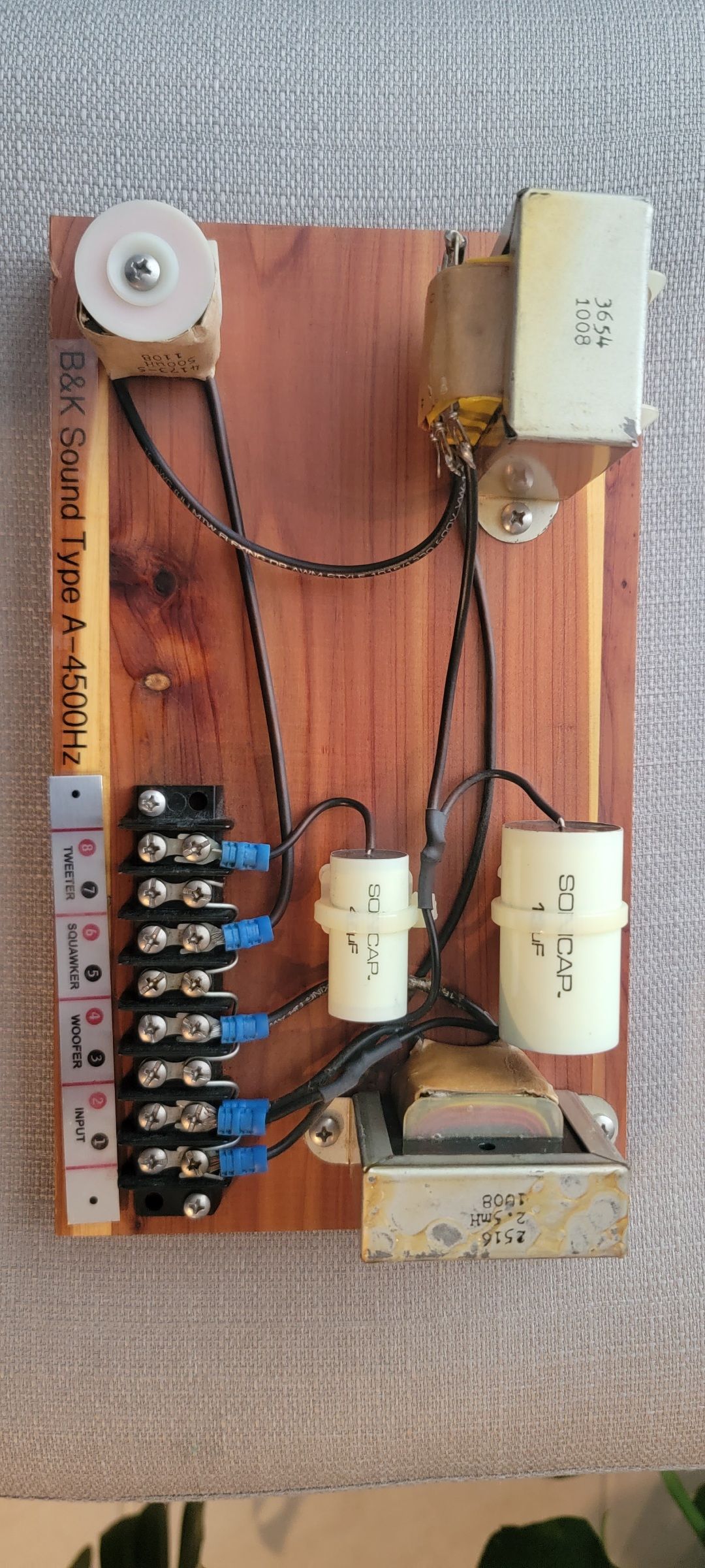
I attached a picture of my crossover.
If someone could answer my question, I will appreciate!
Thank you in advance
Ed
Actually, you have the Crites A-4500's to go along with your CT-125's. It would take some work to convert them to AA's. I like the CT-125's, but found the sensitivity to be too low for the Khorns. It's a great tweeter for the Cornwall or Heresy, if you make tap changes to bump up the voltage to them.
-
1 hour ago, Deang said:
You could measure a K-55-M with an AA to get a complete picture. Would be nice to settle this one.
Seems maybe you can do two port phase plug with the AA, but should not do AK/AL series networks with the single port phase plug driver.
Same as above with K55M
-
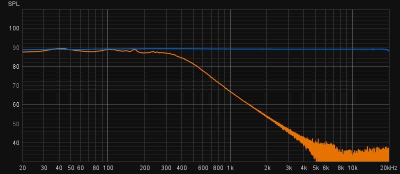
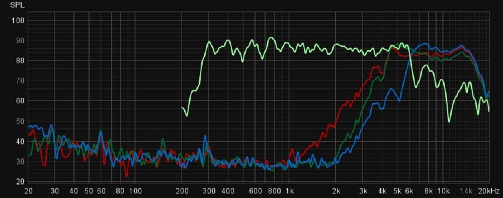
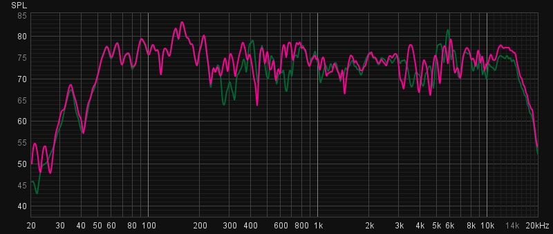
I thought it would be interesting to compare tweeter filters using a K77M. I've never measured a Type A before, so I compared the Type A (RED) with the Type AA (GREEN), and the Type AL/AK (BLUE). The A and AA cross around 4.5khz, while the AL/AK is around 6khz. The Type AL/AK filter does seem more suited to the extended response of the dual phase plug squawkers.
-
9 hours ago, geoff. said:
Maybe I’m missing something?
That is really weird! They do look like solder lugs, but it appears someone tried to remove the solder "globs" for some reason. The + terminal has the normal red spot on the case, but the usual red mark on the solder "glob" is gone along with most of the glob 😕
-
16 hours ago, JCBOHL said:
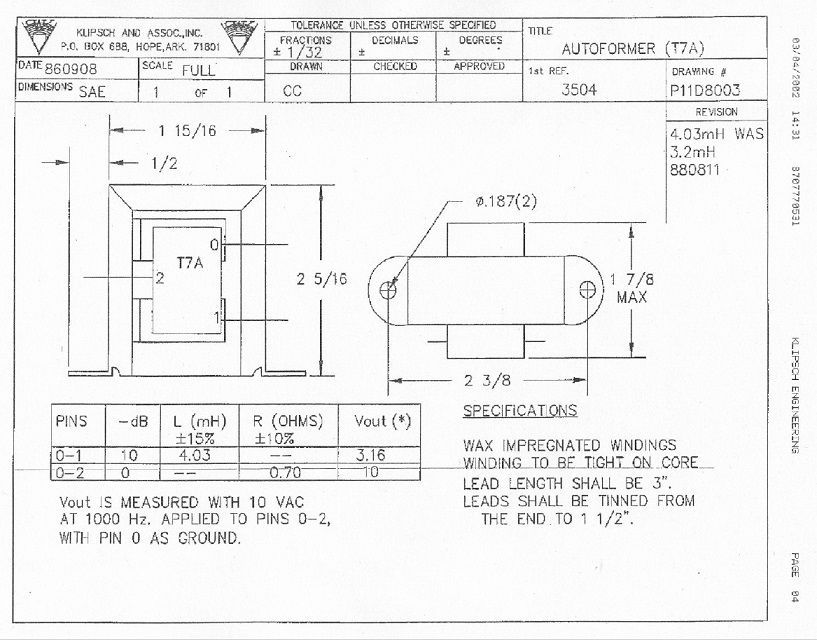
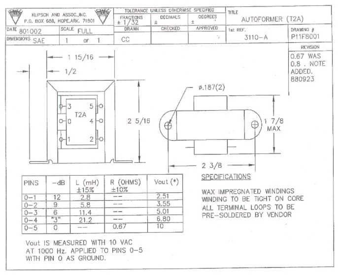
4a. The T7A (I cannot locate a chart for this at the moment) will provide attenuation of -10 dB with the input at 5, output at 2, and the ground at 0 taps. With the component I have, it has leads only at these "tap" setting and no tabs, so am I assume this is fixed in the level of attenuation? (I will not ask about using an inductor here)
4b. The lead at tap 2 actually is two leads and on is common with the 5 lead and the other with the 0 lead. Why is this? In the crossover network both of the tap 2 leads are connected to the same solder point.
Tap names are confusing. In the case of the 3636 and the 3916, X doesn't mark the same spot.
Here's the T7A. The tap names are actually 0, 1, and 2 and the connections are in 0 - 2, out 0 - 1 (-10db).
Like Dean said, the T7A in an inductor, and one end is labeled 0, the other end is labeled 2. Now imagine they are winding the inductor (call this end tap 0). When they reach 31.6% of the windings, they expose the wire and cut it. The two ends of this cut wire are tap 1. The rest of the wire is then directed back to the inductor and continues to be wound until 100% of the desired windings is reached (tap 2)
If the same tap names were used on a T2A (0, 1, and 2), the output voltage would be around -3db due to the winding ratios.
Mike
-
8 hours ago, JCBOHL said:
Thanks for the assistance,
Jeffri B
I'll start with the wiring and move on from there...
3619 -9.8db
3636 -10db
-
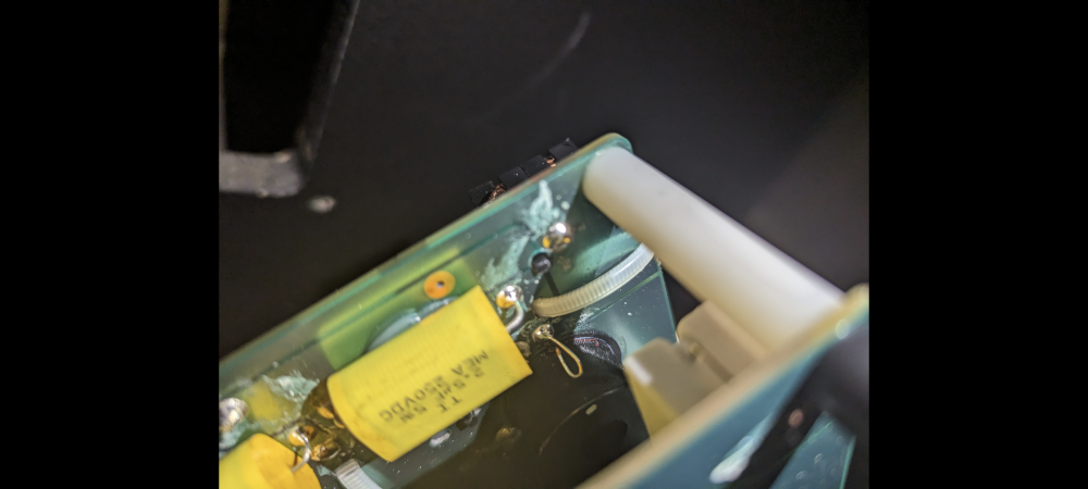
Is this capacitor labeled 2.5uF? I don't see that value anywhere on the schematic.
-
1
-
-
Here are the rest of my findings...
One squawker gasket was missing, the other pretty compressed. New gaskets installed.
Both AA tweeter inductors were secured with ferrous screws and measured 315uh. Replaced with non-ferrous and now both measure 265uh.
One AA's woofer inductor measured 2mh, the other 2.5mh.
Removed doghouse from one speaker. Woofer is K-33-E Square Magnet.
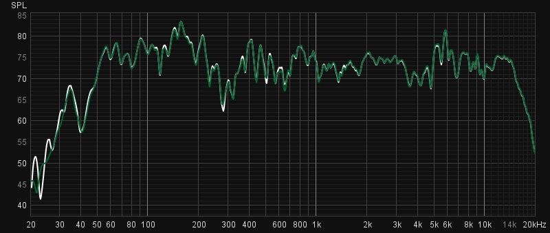
Plots were made on just one speaker, as I wanted to see the how the crossovers measured.
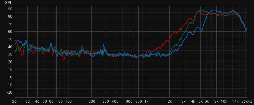
First, I was surprised how little the inductor difference made. White is 2.0mh crossover, green is 2.5mh crossover.
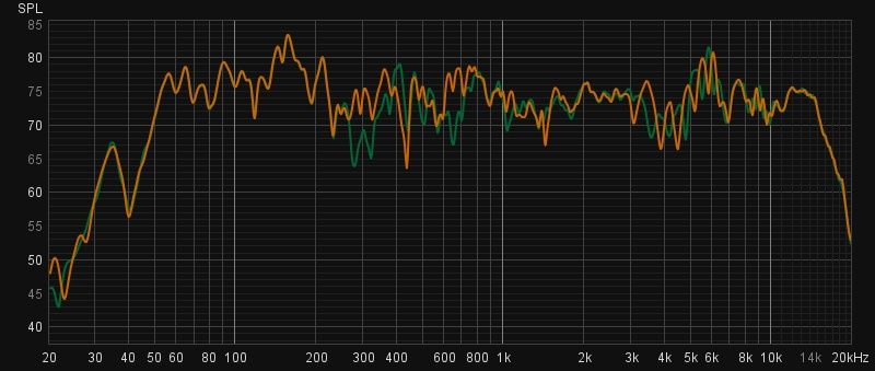
Next I reversed the polarity of the squawker. Green is normal polarity, orange is reversed polarity.
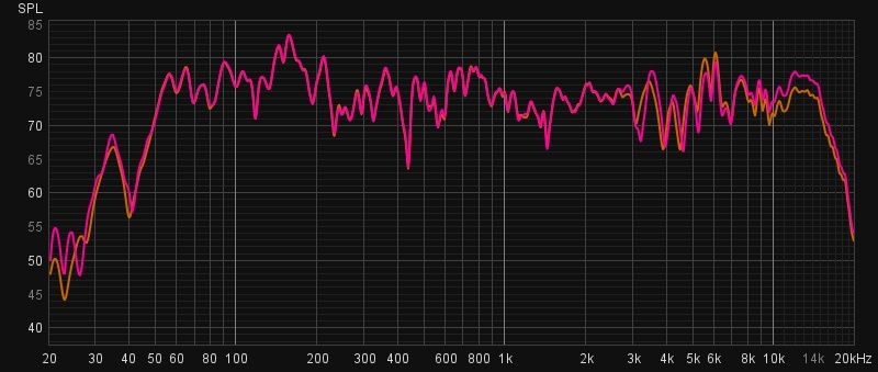
Next is a mod that I had to try out. I've always thought the AA tweeter filter peaked too soon, resulting in the SPL bump between 5khz and 6khz. I added a 4uf capacitor across the second 2uf of the tweeter filter and remeasured. It did decrease the bump by 4db, but it also extended the tweeter response (much flatter). Orange is 2uf, red is 6uf.
Last is a comparison between the stock AA (Green) and the modded AA (Red).
I plan on adding the notch filter to tame the 160hz bump, then I think I'm done!
Mike
-
1
-
-
Is the distortion coming from one speaker or both? If it's just one, switch the cables on the amp side and see if the issue moves with the cable.
-
1
-
-
2 hours ago, henry4841 said:
Anyone know the inductance of the T2A? Perhaps someone can measure and post the number. You will need a decent inductance meter.
The inductance of the entire T2A is not listed, so just multiply the inductance between Taps 0-3 by four to get 45.6mH.
-
1
-
1
-
-
3 hours ago, Scott Grammer said:
I'd actually like to have a pair of T2A's, but they seem to be difficult to find. They work quite a treat controlling horn drivers. I have become convinced of that lately.
Send a PM to @Deang
He may have a pair of new T2A's he could sell.
-
1
-
-
44 minutes ago, OO1 said:
did you check to see if the woofers are the Original K-33 the lascala have either a bottom woofer access panel or an upper panel
Not yet. I promised @archdukeobvious I'd do as little damage as possible and these things are heavy.
-
1
-
.png.794fd6c18eaaf3199d737c2e049a5355.png)
.png.67a4ec94cdcb173c053fa74acfb489cf.png)
.png.da8c694c82cdc84cc371db7e20e19c1d.png)
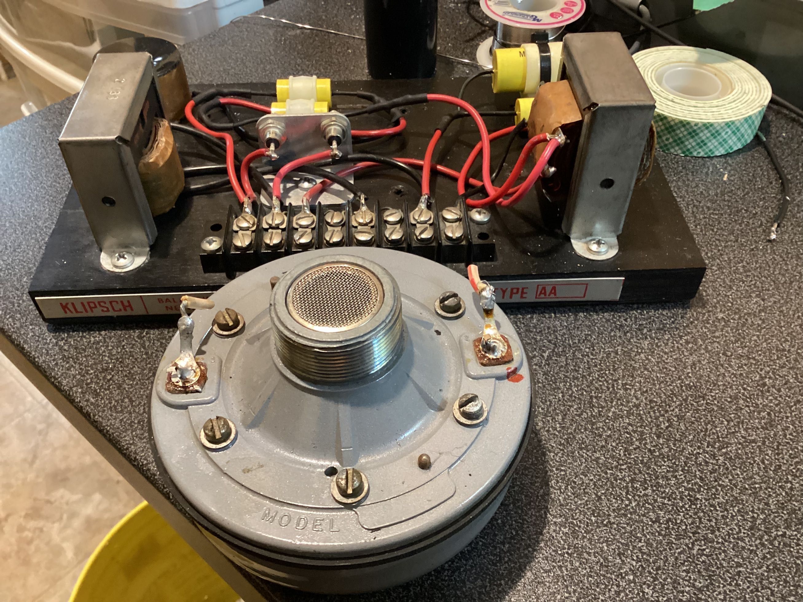
The Amazing Autotransformer
in Technical/Restorations
Posted
The Heresy I and II used autoformers. Klipsch went to series resistors starting with the Heresy III.
The crossover in your Heresy IV is pretty complex. Are you asking if autoformer(s) could be used in those?