mboxler
-
Posts
574 -
Joined
-
Last visited
Content Type
Forums
Events
Gallery
Everything posted by mboxler
-
Type AA crossover rectangular capacitor replacement
mboxler replied to Tizman's topic in Technical/Restorations
I've been told that my T2A model isn't exactly accurate when it comes to phase, so I'm not sure. I don't think tap 0 greatly affects the tweeter circuit (it's more the series 13uf/2uf). That said, it looks like the tweeter circuit greatly affects the squawker circuit. Again this is my Type AA, T2A model, with the squawker (14.2 ohm resistor) on tap 4 (-3.35db). The red trace is the tweeter circuit disconnected. Mike
-
Type AA crossover rectangular capacitor replacement
mboxler replied to Tizman's topic in Technical/Restorations
My fault. I noticed differences in the plots and was curious why. Although the major difference had to do with the load resistor (I use 8 ohm), I couldn't help but notice the autoformer model difference as well. Apologies to the OP. Mike -
Type AA crossover rectangular capacitor replacement
mboxler replied to Tizman's topic in Technical/Restorations
Agree! Taps 0 - 3 equals one half, or 5/10 of the total turns. So...(5*5)/(10*10) = 25/100 = .25 44mh * .25 = 11mh. I can do the same everywhere. Taps 5 - 4 equal 3.2/10 of the total turns. (3.2*3.2)/(10*10) = 10.24/100 = .1024 44mh * .1024 equals 4.5056mh Taps 4 - 0 equal 6.8/10 of the total turns. (6.8*6.8)/(10*10) = 46.24/100 = .4624 44mh * .4624 equals 20.3456mh If you really want easy -3db, use 2.93/10 for taps 5 - 4 and 7.07/10 for 4 - 0. We're probably stating the same thing in different ways (Isn't math great)! Mike -
Type AA crossover rectangular capacitor replacement
mboxler replied to Tizman's topic in Technical/Restorations
Sorry if I'm not following your math. Let's say the inductance between tap 0 and tap 5 is 43mh. Also, keep in mind that tap 4 on the T2A is actually -3.35db, 10 volts in = 6.8 volts out. Taps ratio of total turns Ratio of total inductance 5-4 .32 .1024 or 4.4032mh 4-3 .18 .0324 or 1.3932mh 3-2 .144 .020736 or 0.891648mh 2-1 .106 .011236 or 0.483148mh 1-0 .25 .0625 or 2.6875mh Not sure if this gets us on the same page, but I tried. Mike -
Type AA crossover rectangular capacitor replacement
mboxler replied to Tizman's topic in Technical/Restorations
Okay, I saw this earlier but never commented... The simulation of the autoformer isn't quite right. There are a few good models, this is the one I came up with. The autoformer is one big tapped inductor, not several inductors in series. You will notice the K directive. It tells LTspice to mutually couple all the series inductors. The total inductance of my model is around 44mh, tap 0 to tap 5.
-
Type AA crossover rectangular capacitor replacement
mboxler replied to Tizman's topic in Technical/Restorations
Would you please post one of the LTspice models? Also, I'm not a bat 🦇. Could you end your simulation at 20000 hz? My simulation is quite a bit different. Thanks, Mike -
Finally got REW to work, I think. Discovered I can use my computers Line In to capture the voltage across the crossover outputs. Line Out-->Amplifier with Volume control-->Crossover Input-->Crossover Output (with dummy resistor across the output as well)-->Line In. I had success with a simple 47uf capacitor/8 ohm resistor circuit combined with a 2.5mh inductor/6 ohm resistor circuit...Pretty close! Unfortunately, my test "jig" broke (two wires soldered to a pcb mount 1/8" jack's pins). Ordered a breakout board that I hope works better. I had to be careful and use an amplifier with single ended outputs. I assume connecting an amp with bridged outputs to the Line In jack would be a disaster. I also don't know what the input impedance of my computer's line in jack is. I assume it's impedance, in parallel with the test resistor, might affect the REW test. Curious how others test crossovers before installing them in their speakers. Mike
-
Using only the mid / high portion of the A/4500 crossover
mboxler replied to jjbraga's topic in Technical/Restorations
If using active filter for high pass... It would be best to bypass the 13uf capacitor. Disconnect the 13uf capacitor from the crossover input, and run a wire from that same spot to tap 5 of the autoformer. If you are not comfortable with soldering you could use an alligator clip to connect to that tap for testing. Unfortunately, the 4uf capacitor is in series with the 13uf capacitor, effectively creating a 3uf capacitor to the tweeter. Once you bypass the 13uf capacitor, the 4uf capacitor is on it's own. The voltage across the tweeter will increase sooner than it would with the 13uf connected. -
Using only the mid / high portion of the A/4500 crossover
mboxler replied to jjbraga's topic in Technical/Restorations
Will your active crossover be sending the low-pass signal to the woofer amp and the high-pass signal to the A/4500 amp? Or will you be sending the full signal to the A/4500 amp? Mike -
Just to be clear... Run a wire from the terminal cup input straight to the K-33, removing the connection to the inductor. Run cables from your amp to the new AK-3 sitting in the top hat. Run cables from woofer out to the bottom terminal cup terminals. Run cables from squawker out and tweeter out to the K-55 and K-77 (terminal cup not used). The upper terminals on the terminal cup will be unconnected (looking from the outside). Clever, as long as you know that the low pass fuse is now between the crossover and the K-33 and the high pass fuse is now unused. That should be okay. Mike
-
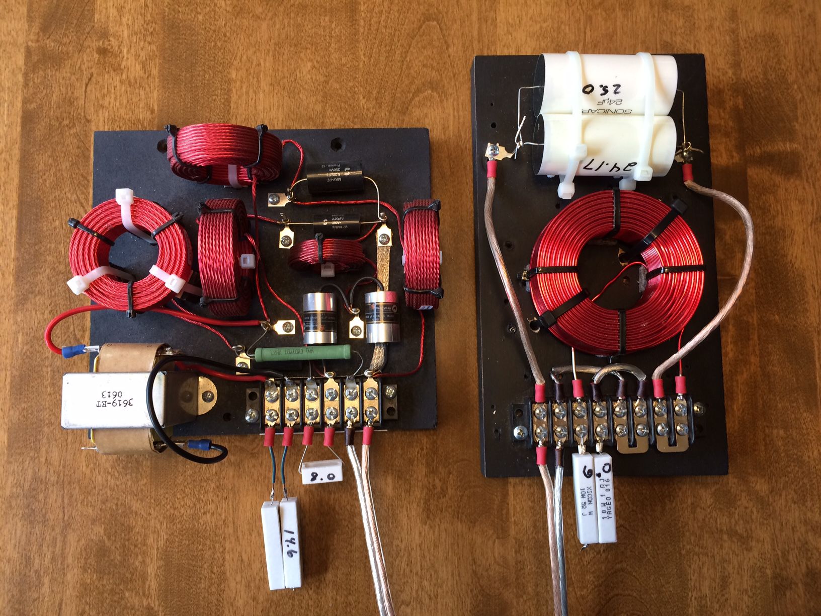
Here's what I made... Another option is to replace each 70uf capacitor with a 50uf and be done with the woofer section. The inductor should be fine. Then run a cable from the HF output of the terminal cup to the HF input of the crossover. Mike
-
Are you wanting to stream wirelessly from your wife's laptop to a device connected to your Sony receiver? Does your receiver accept S/PDIF or do you want to connect via RCA? Do you want to control your playback from a tablet/phone? Do you also want the ability to stream music over the internet...Spotify, Tidal, Pandora, etc? My favorite device is the Squeezebox Touch (no longer made but still very popular). You would need to run a server program on your wife's laptop however. I have built Squeezebox devices using ESP32 as well. DIY, but a blast to play with! Mike
-
I do have a folder containing all the AP-XXX schematics that I downloaded from Al's website a long time ago. It contains his AP-700 schematic. Let me know if you want me to PM you that folder. Mike
-
Do you have the schematic for the ES400? If not, there's one on Al's website, in the Extreme Slope section. I assume it's the latest schematic. I believe you can take those values and divide all of them by 1.75 (700/400) to get an ES700. I think the first series inductor is 3mH (?). Do you already have the ES5800, or were you planning on a 2-way system? If you would like, I can try to run some before/after simulations just to see how the old/new values play together. I can't guarantee the resulting values will equal Al's ES700 though. Maybe wait until someone posts an official schematic before trying this approach. Mike
-
Tuning ALK's Extreme Slope Networks for best sound,
mboxler replied to RickD's topic in 2-Channel Home Audio
Which autoformer taps are you currently using? If I remember correctly, I was using -12db at the least to tame those high sensitivity drivers. Mike -
This may help with I2S https://hackaday.com/2019/04/18/all-you-need-to-know-about-i2s/ Yes, the amp has a built in DAC, otherwise it's pretty much identical to the MA12070. In fact, all of the analog input pins on the MA12070 are digital input pins on the MA12070p. Since I can't get analog out of the ESP32 (I2S or SPDIF only), the MA12070p is a great fit. Here's the MA12070p datasheet. Infineon-MA12070P-DS-v01_00-EN.pdf Mike
-
This took a lot longer to get going than it should have 🙁 This is an ESP32-WROVER (running Squeezelite-ESP32) connected to a Merus MA12070p (Class D) reference board (on the left). The MA12070p chip is I2S input only, hence the wires for bit clock, word clock, and data. Other wires are for I2C connection. I'm a Squeezebox fan, and with this setup I can stream Tidal, Spotify, Radio Paradise, etc. Playing through a pair of full range speakers now but really sounds nice! Mike
-
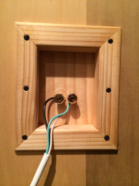
An example of this setup. The resistors are there for testing only 😎
-
I guess I should have asked what the high pass frequency is from the DSP. If it's low enough, and the slope is steep enough, you won't notice a difference. Sorry about that. I have a pair of ALK ES5800t crossovers in the Garage Sale that would replace the ALK-3 top hat section and give you more control over the high pass signal to the squawker/tweeter. Mike Mike
-
I assume you are sending the full signal to the top hat crossover and not the high pass from your DSP???
-
Sorry, need to get my eyes checked (which happens to be this Thursday). What I meant was drastically increase all the inductor values. I changed all my mH to H. In your case 5.83m becomes 5.83, or 5.83h. I should have said multiply all the inductor values by 1000 (?). In my screenshot, I placed a 13uf capacitor in series with each load, using a 14.6 ohm resistor across taps 0-4. The plots are the voltage drops across the capacitor. Gray is the autoformer in Herry. Green is mH. Red is the DATS sweep. Sorry again for my poor explanation.
-
Kind of. If you were to plot V(Tap5)/I(V1) you will get the impedance across taps 0-5 of the autoformer. The impedance plot of my DATS test was much closer to the "Henry" vs the "MilliHenry" values. I can't guarantee my DATS test was accurate, but the results were surprising.
-
Thanks for the link. I had a DATS V3 sitting around and tried it out. I attached the DATS to taps 0 - 5 of a 3636 and a 14.6 ohm resistor to taps 0 - 4, and was able to use the exported file as an LTSpice sub circuit. I compared that to my 3636 simulation and was bummed that it didn't match. As far as I can tell, the real 3636's inductance had no effect on the lower frequencies. I got the idea to change my 3636 simulation inductors from Mh to full Henrys 😮. Reran the simulation and got an almost identical match. I don't understand why it worked, but I was wandering if you could try this yourself and see what happens. Mike
-
Hey @Wirrunna Actually, the network will see the 10 ohm resistor in parallel with the impedance reflected across taps 0 -5 of the autoformer. In the case of the tweeter network, if the tweeter is running off taps 0 - 4, the impedance across taps 0 - 5 will be around 16 ohms. 16 ohms in parallel with the 10 ohm resistor is around 6.1 ohms. If using output taps 0 - 3, it will be 7.6 ohms. Sorry if you already know this, but I stumbled upon a neat Spice directive, the .step param. Instead of giving the resistor a fixed value (10 in your case), you can assign it {R_Value}. Then, add a Spice directive (the .op tab on the top right), and paste something like this .step param R_Value list 6.1 7.6 When you run your simulation, and click on the voltage across the resistor, you will get two plots, one for the 6.1 value and one for the 7.6 value. I find this handy when simulating capacitor and inductor values as well. Mike
-
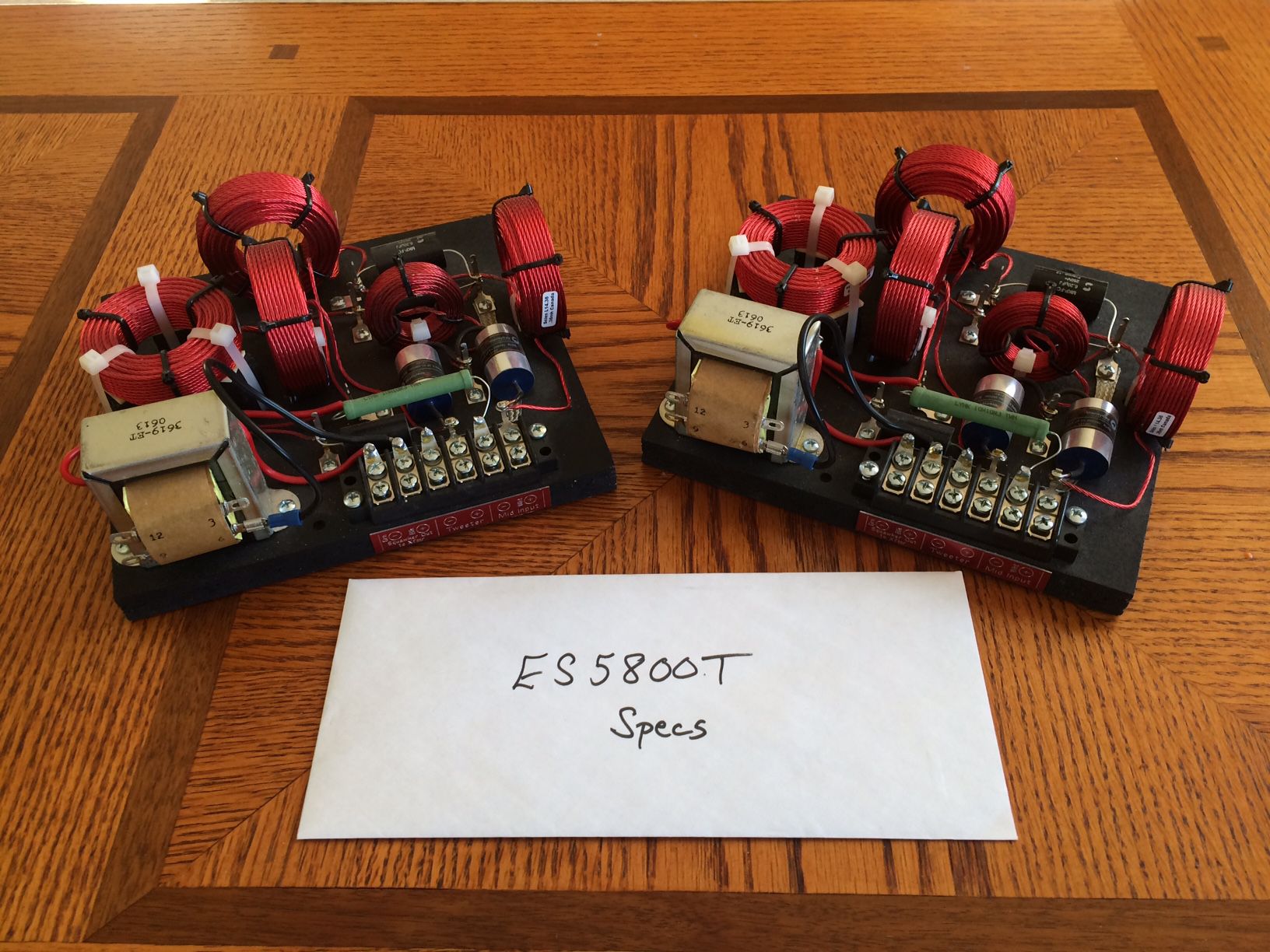
These are the bi-amp versions of Al's ES5800 crossovers. They split the high pass signal, sending frequencies below 5800 Hz to the squawker and frequencies above 5800Hz to the tweeter. I had Al modify the ES5800, eliminating the tweeter autoformer and moving the squawker autoformer from the ES400 to the ES5800t. The idea behind the design is to attenuate the squawker to match the tweeter, then adjust the gain of the high-pass amp to match the low-pass amp/woofer SPL. Although these are designed for an active bi-amp system, I have also run these fully passive, using an simple inductor/capacitor network ahead of the ES5800t. $320 shipped to the lower 48. Mike
- 1 reply
-
- 2
-

.png.51903b190968cfb644331e1a9b5a0e90.png)
.png.253b76f0a052dbfbf79b268df2ed03f9.png)
.png.e4eb4bacdc3f1d5c5fe7b69c53c1b805.png)
.png.b340220f5fdb588d5a3aa60453c9049f.png)


.png.814422116866fc016c50e358b9b3cab1.png)