mboxler
-
Posts
574 -
Joined
-
Last visited
Content Type
Forums
Events
Gallery
Everything posted by mboxler
-
How many watts can the amps put into a 4 ohm load when run single-ended? I wonder if there's a current limiting issue.
-
I assume you like the last track on the cd, Epilogue and Hymn. It is also one of my favorites.
-
As with all transformers, watts in equals watts out, so let's use Ohm's Law. As an example, let's use a T2A autoformer, and apply 2.83 volts to taps 0-5. Taps 0-4 will connect to a 14 ohm K-55 driver at 2.00 volts (-3db). 2 volts into a 14 ohm load equals .2857 watts (watts = volts squared/resistance, or 4/14). Since there's .2857 watts output, there's got to be .2857 watts input. 2.83 volts at .2857 watts equals 28 ohms (ohms = volts squared / watts, or 8 / .2857). As you can see, taps 0-5 appear to be a 28 ohms load. Hope that helps!
-
The turns ratio squared of the 3507 is around 6.4, so the series load on the 3uf cap will always be 6.4 times the impedance of the driver in parallel with the inductor. If the cap were on the other side, it would need to be 6.4 times larger to get the same results.
-
Talk about cool! https://positive-feedback.com/reviews/hardware-reviews/agd-production-vivace-gantube-monoblock-amplifiers/ Didn't know GaN transistor based amps were available. Pricy.
-
Could you take a picture from further away so we can see the ends of the other cable?
-
Did you ever try to connect the transformer outputs to the audio interface board, bypassing the input op amps? I sold my EVM before trying this out. Mike
-
Without knowing the crossover schematic, let's assume a 1 mh inductor in series with a 4 ohm load. At 637 hz (the -3db point), the impedance would be 5.66 ohms. 8.95 at 1274 hz. All I'm saying is that I wouldn't classify this as a 4 ohm load on the transformer.
-
On top of that, splitting the crossover does not create separate 4 ohm and an 8 ohm circuits, if I understand what is being implied.
-
I assume the 20 volt preamp output would be for a current amplifier instead of a voltage amplifier.
-
The miniDSP 2 X 4 input max is .9 volts or 2 volts, depending on a jumper setting. The output voltage, however, is set at .9 volts. If the input setting is 2 volts, the output has a 7 db insertion loss. Mike
-
Interesting! Someday I'll re-install my ALK Universals into my K-horns and experiment. I have a pair of 1.0 mh inductors that I can put in series with the 1.3 mh in the crossover. I assume the yellow graph is the woofer, with the woofer current lagging the mid driver current by 90 degrees? Thanks for the info! Mike
-
Not to create more work, but I'm curious what the voltage drop across the 1.3 mh inductor is at 430 hz. Maybe 1.3Vpp??? Mike
-
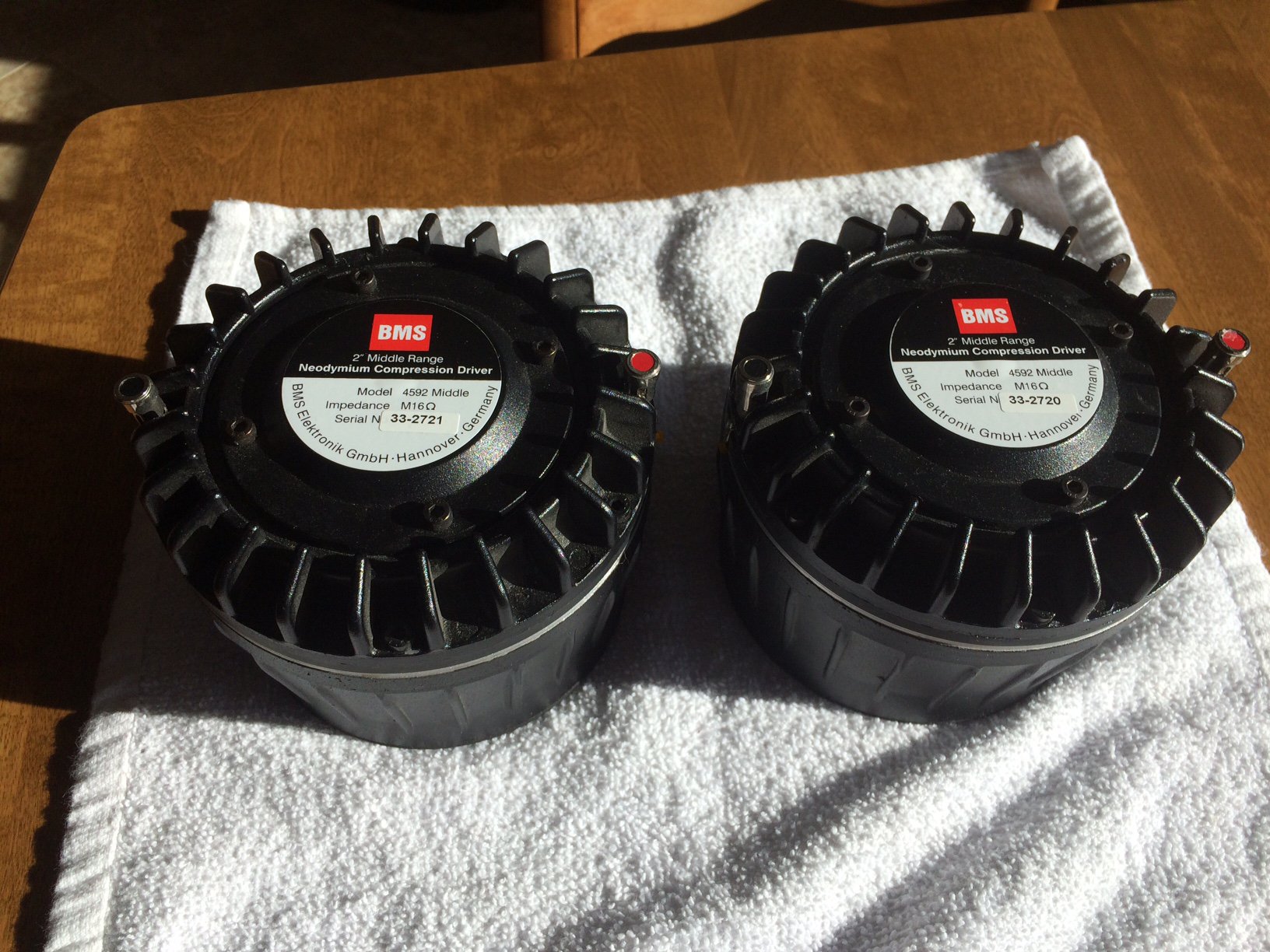
Selling my pair of BMS 4592ND-Mid (16 ohm) drivers. Purchased new from Greg Roberts in 2011. Never abused. Incredible drivers. SOLD includes PayPal fees and shipping to ConUS. Mike

-
When you say "measured", are you passing a 430 hz signal to the speaker, checking the voltage across the crossover input, then checking the voltage across the woofer output? The woofer out should be the input times .707. Mike
-
I actually have three of these. One for my RF-83's and two for my LXmini's. I think they are great sounding amps, and the variable gain feature comes in handy. Just make sure the power supply is adequate for your needs. Mike
-
6000f and bi amp-ing (horn/woofer wattage?)
mboxler replied to daemonix's topic in General Klipsch Info
Deleted 'cause I don't know what I'm talking about 😶 -
It's five o'clock somewhere! This will be fun. Bringing as much stuff as I can, not knowing what the issue(s) are. Even found the old diaphragms from my Heresy's K-52-H mids, just in case his contains the Heppner K-52-H as well and one or both are bad. Also a pair of K-77-M's. Hopefully it's something simple, but we'll see. Mike
-
Looks to be in the Denver area. If you are reasonably close to the Golden area, I'd also be happy to help. Mike
-
Heil Air motion transformer for Cornwalls
mboxler replied to jwgorman's topic in Technical/Restorations
Thanks, Chris! Still learning, and I could never figure out what .zma files were. Opened it up in notepad and it became clearer. At first I thought the phase column represented the electrical phase shift across the driver. But it now appears that it is acoustical phase shift. Correct??? Again, thanks for the info. Mike -
Heil Air motion transformer for Cornwalls
mboxler replied to jwgorman's topic in Technical/Restorations
Chris Am I reading the Crites .zma file correctly? Looks like the driver, at 800 hz, is 8.5 ohms and 38 degree phase (inductive). Seems as though a 1.7 mh inductor would be needed, or am I missing something. Mike -
Help modifying AA crossover to work with Volti Upgrade
mboxler replied to Godataloss's topic in Technical/Restorations
You could try these https://www.parts-express.com/speaker-l-pad-attenuator-50w-mono-3-8-shaft-16-ohm--260-254 between the squawker output of the crossover and the BMS driver. You are going to need around 12-14 db attenuation, and they don't specify the maximum attenuation of the l-pad. Are you using the K-77 tweeter? Gorgeous speakers! Mike -
And which BMS mid driver...8 ohm or 16 ohm?
-
Interpreting These Crossover Measurements - ALK Universal
mboxler replied to naaac's topic in Technical/Restorations
That is old! If you want to stay at 500hz, 5mh should work. 6.4mh for 400hz. If you get a 5mh, you could wire it in series with the 1.3mh, giving you 6.3mh, and see if you like it.- 17 replies
-
- 1
-

-
- klipschorn
- alk universal
- (and 4 more)
-
Interpreting These Crossover Measurements - ALK Universal
mboxler replied to naaac's topic in Technical/Restorations
I was hoping you had the stock 1.3mh inductor, as that would be way too low, and would account for your measurements. But the 5mh should have been better. Any way to measure the 5mh to verify it's value?