


mboxler
-
Posts
574 -
Joined
-
Last visited
Content Type
Forums
Events
Gallery
Everything posted by mboxler
-
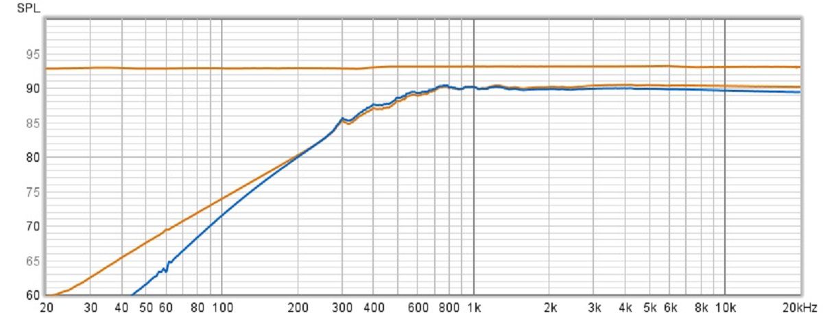
If you have the original crossover's T2A, it would be interesting to replace the 3654 with it. I don't have a 3654, but it's supposed to be the same as the 3636 that I do have, less the extra taps. Here are plots of the 3636 (orange) and T2A (blue). I used a 13uf capacitor and tap 4 is connected to the K-55-M in my Khorn. Even though tap 4 of the T2A is -3.35db vs the 3636's -3db, the voltage across the K-55-M is actually a little higher in the 400-600hz range. This is due to the difference in inductance between the two autoformers. Not sure I would hear the difference, but interesting nonetheless. Mike

-
Again I ask...how does one know if a capacitor is out of spec when we don't know the factory specs to begin with? It would be interesting if you could measure the capacitance of the old caps vs new ones. It would very interesting if you could measure the ESR of the old vs new caps, at various frequencies.
-
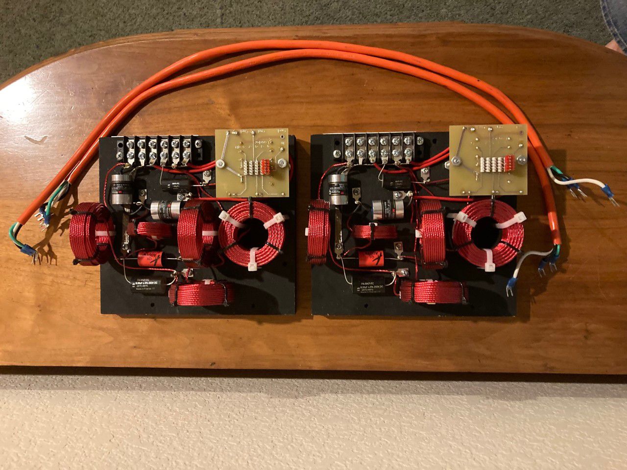
Selling a pair of ALK ES5800's. Includes 3-Wire cable to connect to ES400 thru ES700. $375 shipped (ConUS) includes PP fees. Mike
-
This would seem to been a good example of whether capacitor ESR really matters. In the Chorus I circuit, the 15 ohm resistor is in series with the capacitor's ESR. If the capacitor's tolorance is 5%, it would be anywhere from 14.25 to 15.75 ohms. Couldn't the value of the resistor have a greater impact on the total impedance than the ESR of the capacitor?
-
I find myself fortunate to have joined this forum years ago. The Klipsch crossovers fascinated me, and I really wanted to learn what the capacitors, inductors, and autoformers did in a circuit. It was through modifying, measuring, and listening that I was able to learn. I will always be grateful for those types of discussions, and to all those that contributed to them.
-
mfd is the same as µF...microfarad. As I understand it, some companies had trouble printing µF on their capacitors so they went with mfd.
-
Starting to wonder that myself. This is the voltage across the K-33E installed in my Khorn, connected to various filters. Wouldn't the horn loading also come into play? Am I wrong thinking that the driver is a part of the network? If I were to use a 4 ohm resistor in series with a 2.5mh inductor, the plot would end up with a corner frequency of 255Hz, and then drop by 6db per octave after that. That's not what happens across the woofer terminals when using an A or AA, as the voltage drops less than 3db per octave due to the inductance of the voice coil. For some reason I found this interesting.
-
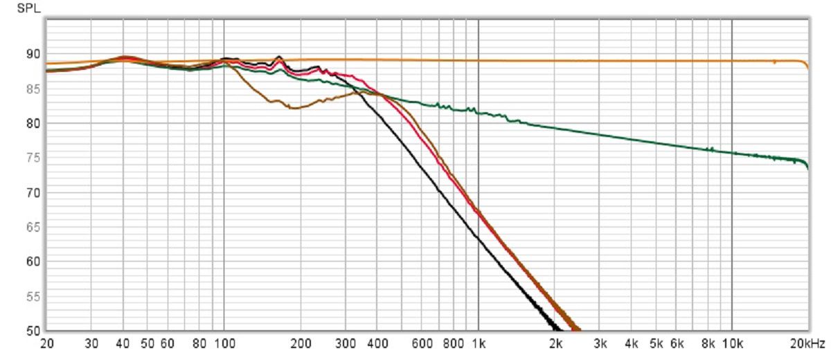
I was interested in the voltage transfers of various filters across the K-33E mounted in my Khorn. I was surprised how much the voice coil affected the A and AA transfers. Green A and AA Black AK-2 Red AK-3 Brown AK-4 If anyone knows the difference, if any, between the AK-4 and AK-5 I can measure that as well. Mike
-
Hey Dean The Mid Range Horn picture shows a T5A autoformer, indicating this is an AK-2 crossover. Will you bother just recapping these or will you upgrade them to AK-3's? Mike
-
I know nothing about professional recording studios, but do they use cable lifters? Seems to me that if not doing so caused an issue it would end up on the original recording.
-
I assumed the K-55-M was around 3db hotter that the K-33-E, so I added that to approximate the SPL. Probably not a good idea?
-
Added a plot of the AK-3 voltage across the K-33-E. I added 3db to the voltage across the K-55-M to simulate it's higher sensitivity.
-
I can only assume that the high pass to the K-55-M was overdamped (if that's the bark you are referring to) to compensate for the new low pass to the woofer. The AK-3 voltage to the woofer is down 3db around 350hz and drops quickly (12db per octave) after that.
-
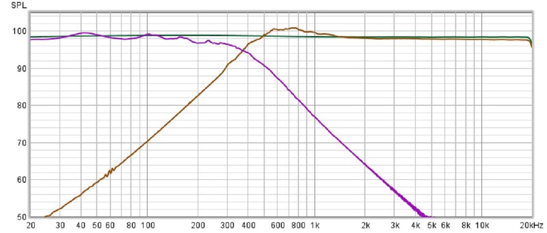
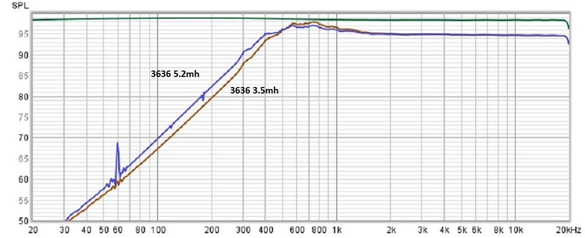
Dean said it well...I'm full of plots 🙂 I didn't have a 3.5mh inductor, but did have a 3.3mh air core. I cheated and used a ferrous screw of just the right length to place in the center of the inductor and raise the inductance to 3.5mh. As I thought, the 3.5mh inductor in parallel with the inductance between taps 0 - 3 of the 3636 got me to my target 3mh. The brown plot is that voltage across my K-55-M. I then replaced the 3.5mh with a 5.2mh (no 5mh per the schematic in my stash), resulting in the blue plot. Tried to get rid of the 60hz spikes and the harmonics, but failed. The path to the -4db point differs, but not sure the difference is audible.
-
Crossover Capacitors and Crossovers In General
mboxler replied to Curious_George's topic in Technical/Restorations
I thought one had to calculate the Impedance |Z| and the Phase φ of each capacitor and then add those two results in parallel. Using a few online calculators I came up with a combined ESR of around .92 ohms doing so. -
Deano is an approved Klipsch network builder
mboxler replied to Chief bonehead's topic in Technical/Restorations
Congrats, Dean -
Crossover Capacitors and Crossovers In General
mboxler replied to Curious_George's topic in Technical/Restorations
It's all about caps, taps, and coils 🙂 If your Crite's AA came with a 3636, then there will be a subtle change as shown in the plots I attached. A little more voltage to the squawker between 300 and 500hz and a little less after that. I doubt I would hear that. The T2A inductance values on the spec sheet are +/- 15%. It would be interesting if you could measure the inductance on both T2A's just to see how far off, if any, they are from spec. Again, I'd measure between taps 0 - 3 and multiply that by 4, or between taps 0 - 1 and multiply that by 16. -
Crossover Capacitors and Crossovers In General
mboxler replied to Curious_George's topic in Technical/Restorations
I figured out how to simulate autoformers in LTspice a while back. At that point I realized that the inductance does matter, unless you use the "swamping" resistor. My point is that I wish I could have been a part of that conversation knowing what I know now. Another case in point is the 5mh value of the shunt inductor on the AK-3. It's in parallel with the 7.3mh inductance between taps 0 - 3 of the T4A, resulting in a 3mh shunt inductor across the K55M. On the AK-2, the inductance between taps 0 - 3 is 11.4mh, therefore a 4mh shunt inductor was used to reach that 3mh target. Coincidence??? -
Crossover Capacitors and Crossovers In General
mboxler replied to Curious_George's topic in Technical/Restorations
I remember reading this thread started by @Crankysoldermeister when Dean was having trouble measuring the 3636 inductance. Both Al and Bob chimed in, but their point was that the inductance meant nothing...the level of attenuation is all that matters. I can understand Al's point only because his resistor "swamps" out the autoformer inductance anyway. It's my understanding that the large inductance between taps 0 - 5 may make measurements difficult. Another way to measure is across taps 0 - 1, which is 25% of the total windings. That inductance times 16 should be the inductance across 0 - 5. I do worry that my numbers are off no matter how I measure. -
Crossover Capacitors and Crossovers In General
mboxler replied to Curious_George's topic in Technical/Restorations
According to the specs, the T2A's total inductance is 45.6mh (11.4 *4). The inductance of the 3636's is pretty high, and I think that messes with my LCR meter, so I measure the inductance between taps 0 and 3, then multiply that by 4. I end up with one at 88.8mh and the other at 76.8mh. -
Crossover Capacitors and Crossovers In General
mboxler replied to Curious_George's topic in Technical/Restorations
Got a feeling you knew I'd react to this 🙂 Here are LTspice plots of the voltage across the squawker (in this case a 14.6 ohm resistor) in an AA crossover. The green is tap 3 of a T2A, the red tap 3 of a 3636. The lower inductance of the T2A contributes to the difference in slopes. Noticeable??? I have always found it interesting that the impedance of the tweeter circuit attached to tap 0 increases the attenuation to the squawker by nearly 1.5db.
-
Crossover Capacitors and Crossovers In General
mboxler replied to Curious_George's topic in Technical/Restorations
Whether there is a loss or not depends on how you define sensitivity. Is it at 1 watt or at 2.83 volts? If you use 2.83 volts, then the resistor will not change sensitivity, it will just double the current draw from the amp. I believe that's Al's argument on the subject. If you consider the K55 driver 16 ohms, then same outcome can be reached by placing a 16 ohm resistor across the driver, and placing an 8 ohm Lpad before the resistor/driver combo. -
Crossover Capacitors and Crossovers In General
mboxler replied to Curious_George's topic in Technical/Restorations
Although I don't consider myself part of the "understanding" group, here's my take on capacitors. I'll focus on the 2uf value since that's the value of choice in the Heritage tweeter circuit. I bought some 2uf polyester caps off the Bay to play with. I feel that ESR isn't important at audio frequencies, and because the dissipation factor of all dielectrics changes with frequency, ESR actually decreases as frequency increases. Here are my measurements of these caps... 1000hz, reactive impedance 80 ohms, ESR .37 ohms. 10000hz reactive impedance 8 ohms, ESR .07 ohms. In either case, the reactive impedance overwhelms the ESR, making it irrelevant??? Again, I'm no EE, so please correct me if I'm wrong. Mike -
Crossover Capacitors and Crossovers In General
mboxler replied to Curious_George's topic in Technical/Restorations
Getting new carpet installed today. You don't realize how much crap you have until you have to move it out of the way 😥 -
Crossover Capacitors and Crossovers In General
mboxler replied to Curious_George's topic in Technical/Restorations
I, too, wonder at what point a measured difference is audible. Below is an LTspice plot of the voltage across a K55 (simulated by a 14.6 ohm resistor) in an AA circuit. The green plot is with a T2A autoformer, the red, a 3636. Even though the T2A's tap 3 is -3.3db vs the -3db on the 3636, the T2A is "hotter" at the crossover point due to it's lower inductance. As frequency rises, however, the shunt impedance of either autoformer is so high that it becomes irrelevant.

.png.ed028bdb0eb4951091002b4342156166.png)
.png.6617da365b3a6b1d060693aed8d18e78.png)