


mboxler
-
Posts
574 -
Joined
-
Last visited
Content Type
Forums
Events
Gallery
Everything posted by mboxler
-
That chip looks more fried more than busted. How did you notice the problem in the first place? Did the left or right satellite speaker suddenly stop working? If so, the chips are probably the same and are each wired bridged to the left and right speakers. Hopefully there were heatsinks attached to the chip amps????
-
Sounds like the woofer is blown to me. Since the upper crossover passes through a 13uf capacitor, it will never show dc resistance, since a capacitor is by definition an open circuit. The 4 - 5 ohm readings you are getting on the good speaker is the sum of the resistances of the woofer and series inductor, no matter which speaker terminals you are connected to. Edit: Forgot that the tweeter circuit is isolated in this crossover, so the 2uf capacitors also create an open circuit.
-
Is VituixCAD more accurate than LTspice?
-
Although this simulation shows the voltage across an 8 ohm resistor, it gives you an idea of the change. Red is .245mh, blue .34mh. Mike

-
Sorry I'm no help, perhaps someone else can chime in. The point I'm poorly making is that the transfer functions of an LPad vs series resistor are different. This is due to the load change on the network. The plot below is a simple high pass to an 8 ohm resistor (driver). I'll use an 8 ohm series resistor to get -6db to make it simple. Brown is 20uf capacitor. Voltage across the driver. Red is 20uf capacitor and 8 ohm attenuating resistor (-6db). Voltage across the driver. Blue is 10uf capacitor and 8 ohm attenuating resistor (-6db). Voltage across the driver. Purple is 20uf capacitor and 8 ohm attenuating resistor (-6db). Voltage across both the attenuating resistor and the driver. Even though the voltage across the driver is always -6db less than the voltage across the series resistor/driver, it can't give you -6db I believe you are looking for across the entire frequency without changing the capacitor. If you want to keep the 20uf capacitor AND get the blue plot, you need a -6db Lpad. Mike
-
Just so I'm clear. At 4000hz the voltage across the resistor and tweeter is .122 volts. The voltage across the tweeter alone is .0940 voltages. That's a -2.27db drop, so the tweeter isn't a resistive 8 ohm load at that frequency. The added 3 ohm resistor dropped the current through the crossover circuit, which also lowered the voltage drop across the crossover circuit. Since the voltage decreased across the crossover circuit, the voltage increased across the load (the resistor and tweeter). You should be able to verify this by measuring the voltage from common to before the tweeter alone, then measure the voltage from common to before the resistor/tweeter combo. Sorry if I'm not following you on this. If you post the schematic I could simulate my explanation. Mike
-
"Math is the only subject that counts" Are there any other series resistors in this circuit? Assuming you have an 8 ohm tweeter, the circuit is designed for that specific load. The series 3 ohm resistor increased the load, and now the circuit sees an 11 ohm load. Think of it as replacing an 8 ohm tweeter with an 11 ohm tweeter. In order to get the same voltage across the 11 ohm tweeter, you need to divide all the capacitors in the circuit by 1.375 and multiply all the inductors in the circuit by 1.375. The Lpad did not change the load on the circuit. Mike
-
Chorus 2 modded with more efficient woofer?
mboxler replied to Bubba_Buoy's topic in 2-Channel Home Audio
Since we're talking about the woofer circuit, I'd be more concerned with the condition of the 68uf electrolytic (?) shunt capacitors. -
Hey Dean How would one know if the windings are loose? Would one or more of the taps feel like a loose tooth? Probably a bad analogy but the only one I could come up with. I have a couple of T2A's from E2's I can send you. The inductance on both is lower than the spec, and they both measure differently from each other. That said, I'd be happy to run some tests on them for you if that helps. Mike
-
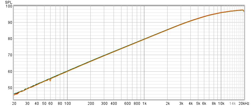
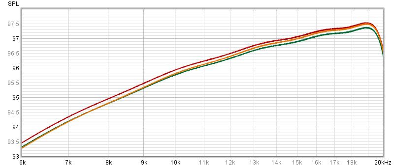
Is this kinda what you are asking? Here's a REW voltage test using three different 2uf capacitors in series with an 8 ohm resistor. The plots are the voltages across the resistor. As you can see in the first plot, they pretty much lay on top of each other. The second one is zoomed in, and they are within .15 db of each other. Red is a Sonicap 2.01uf Orange is a 2.04uf oil can pulled from an old Heresy. Green is a new GE polyester 2.01uf I'm still trying to figure out why my crude setup always shows a voltage drop around 19khz. Mike
-
These are on Ebay. Zooming in on the last picture, looks like L1 is .15mH and L2 is .51mH. Hopefully they are labeled correctly. https://www.ebay.com/itm/255515554642?chn=ps&norover=1&mkevt=1&mkrid=711-117182-37290-0&mkcid=2&itemid=255515554642&targetid=1263433206654&device=c&mktype=pla&googleloc=9028825&poi=&campaignid=16190447015&mkgroupid=128435277530&rlsatarget=aud-1297930287298:pla-1263433206654&abcId=9300820&merchantid=6296724&gclid=EAIaIQobChMI49iKrazp-AIVVBh9Ch0W0wZgEAQYASABEgLtfvD_BwE
-
I don't know how familiar you are with circuit simulations, but if you were to post the exact values you used, I'd be happy to simulate the voltage transfers. Then, I could substitute common capacitor/inductor values and run a new simulation. It might be interesting to see the difference. Mike
-
I think an AK-2 to AK-3 conversion kit would be a great idea. All that is needed is a woofer shunt capacitor, a -4db autoformer, and a squawker shunt inductor. As I understand it, JEM only sells the 100uf capacitor??? What autoformer/shunt inductor combo would one need to make a Klipsch approved upgrade kit? T4A's are hard to come by, and the inductance of the 3636, taps 0-3, is 2.5 times the inductance of the T4A, taps 0-3. Mike
-
I would say the Universals using the 3619 were floating, allowing for a greater number of attenuations. Those with the 3619-ET were not floating, as it is easier to get -1db to -18db attenuation in 1db increments with one of the squawker outputs connected to the common strap AND tap C.
-
You don't specify which autoformer you are using, but I'll assume you are using the -4db taps on a 3636. That's input 0-X, output 0-3 to the squawker. There's no reason why you couldn't attach the tweeter circuit to tap 5 for a +2db boost or tap Y for a +1db boost. You would need to correct and move the low pass inductor to the squawker to do this. As drawn, the load on the .30mH inductor is around 8 ohms, so you are ending up with a 4500Hz low pass to the squawker. If you really want a 6000Hz low pass, it would need to be around .21mH. Now, if you plan on sticking with K-55's or other "16 ohm" drivers, AND you want to be able to change the voltage to the K-77, you would need to place the low pass inductor AFTER the autoformer. For a 6000Hz low pass, use around a .38mH inductor. Mike
-
I'm a little surprised that Klipsch authorized the use of electrolytic capacitors to replace the original film capacitors across the woofer. I believe Michael Crites did the same thing on the AK-3 he sells. Good to know!
-
.
-
I mentioned in another thread that it appears Klipsch liked to have around 3mh inductance across the K-55M, hence the different parallel inductor values for the T4A and T5A. Seems to me that, in order to get the same 3mh using a 3636, one would need to use a 3.5mh inductor in parallel with taps 0-3 of the 3636??? I measure 20mh between taps 0-3 on my 3636.
-
For me, dipping the end of the litz wire into solder flux before tinning really speeds up the process.
-
Looks to me that the 5.6 ohm resistor across the K55 equates to a 4 ohm load on the .15mh/4.3uh components. That's already around 6000hz. Your 8 ohm driver appears to be around 10 ohms at 6000hz. If you put a 6.7 ohm resistor across the PRV D2200Ph you'll end up with a 4 ohm load, and can keep the other component values as is. The .3mh/2.2uh values on the ALK Universal are used for an 8 ohm load and are placed ahead of the autoformer to get the 6000hz low pass. Depending on your speaker, you may need to tweak the low pass to the woofer and high pass to the D2200Ph.
-
It is an interesting circuit, as the 11.4mh inductance between taps 0-3 must have been too high to get the desired transfer function. The 2.5mh inductor is in parallel with the 5.8mh inductance between taps 0-2. That equates to around 1.75mh. That inductance, coupled with the windings between taps 2-3, equates to around 3.5mh. Oddly enough, I believe a 5mh inductor across taps 0-3 (11.4mh) would have worked as well, as that parallel combination also equates to around 3.5mh.
-
I believe the 2.7mH indication on the schematic is the inductance between either end tap and the -6db tap. If you have an LCR meter, measure the inductance between each pair of wires. One pair of wires should measure around 10.8mH, so label one of those wires tap 5 and the other tap 0. Label the third wire tap 3. If all goes well the inductance between tap 5 and tap 3 should equal the inductance between tap 3 and tap 0...around 2.7mH. Mike
-
T5A Seems identical to T2A, less the extra taps, as the inductance between taps 0 - 3 is 11.4mh on both.
-
T4A
-
My brother and I spent half a day trying to figure out why one of his Klipsch subs didn't work. After measuring and swapping parts, it turned out that someone turned one of the knobs so hard that it twisted enough to touch one of it's legs to the leg of another knob. After straightening and tightening everything the leg was no longer shorted and the sub worked perfectly.
.png.45c569ab85016295fda03f5b95921123.png)


.png.15a733dbab43a5cc4a26c503ed6cc483.png)
.png.731075bee25ab73b7151a985371fa0fa.png)
.png.d042d777604f00375e950d02d638d244.png)