fromnowon
-
Posts
35 -
Joined
-
Last visited
Content Type
Forums
Events
Gallery
Everything posted by fromnowon
-
Sure! The base kit was $395 + shipping. Sides, bottom and extra tubes were $25 more; I went ahead and got them and am still finishing the sides (the picture I attached shows them stained only - they are nicely cut and routed. Nice oak pieces. I'm glad I got them - still have to finish and attach them.). It comes in many colors - I picked black. I'm playing my spud through Heresy I's. So far my source has been a Fiio High-Res player (with FLAC files) and I have a small headphone/pre-amp in between the player and the new spud. I think the spud needs a good strong input signal. I found that building it did take effort and some thought. It was fun; I didn't rush and I worked on it on-and-off for the entire week between Christmas and New Years. It was a nice break from my full-time job. I even labeled the "B+ power supply connection" and "Screen Grid bias connection" (ha ha I just felt like labeling those) I feel a sense of accomplishment and it's rewarding to listen now, having had a role in creating the amp. Pretty cool to be listening to the parts I soldered and stripped and assembled/oriented correctly/made sure were well-grounded etc. and it even sounds awesome too! I understand that there used to be a forum dedicated to discussing this amp and related mods. It was at a place called Hawthorne Audio that went out of business unfortunately. I think Jerry is trying to recover those discussions which would be very cool if possible. My impression is that this amp really is a labor of love for Jerry and he was great to work with. Anyway to me, all things considered, it was really worth it.

-
Hello, I built the spud kit referenced above over Christmas break. It was a blast. After about 10 hours of listening now it is really breaking in nicely and sounds great. I contacted Jerry several times with questions and he was extremely helpful. The directions and pictures were excellent. I feel that i learned a lot from this and enjoyed the challenge of trying to build it as neatly as I could. I highly recommend the spud kit. Thanks Maynard for your post which led me to this project.
-
Those are very cool. I love the ruggedness of them.
-
Thanks Bossman. I sent a message. I'm very interested to learn how you adapted your Type E for the D250X (also 8 ohms).
-
Thanks guys. I really don't have any right to expect this kind of help. It's the D250PH. Very inexpensive but it gets into the midrange frequencies very well so I'm giving it a try. Midrange driver: http://www.parts-express.com/prv-audio-d250ph-s-1-phenolic-horn-driver-8-ohm-1-3-8-18-tpi--294-2825 PRV Audio D250Ph-S 1" Phenolic Horn Driver 8 Ohm 1-3/8"-18 TPI Midrange horn: http://www.parts-express.com/prv-audio-wg23-25-1-100-x-40-waveguide-1-3-8-18-tpi--294-2912 PRV Audio WG23-25 1" 100 x 40 Waveguide 1-3/8"-18 TPI. Acoustically loads compression drivers down to 600 Hz. Tweeter: http://www.parts-express.com/dayton-audio-dt250p-8-1-polyimide-compression-horn-driver-1-3-8-18-tpi-8-ohm--270-406 Dayton Audio DT250P-8 1" Polyimide Compression Horn Driver 1-3/8"-18 TPI 8 Ohm Tweeter horn: http://www.parts-express.com/selenium-hm11-25-1-exponential-horn-60x60-1-3-8-18-tpi--264-306 Selenium HM11-25 1" Exponential Horn 60x60 1-3/8"-18 TPI. Minimum frequency: 1,200 Hz I know this is not a DIY forum. Thanks again.
-
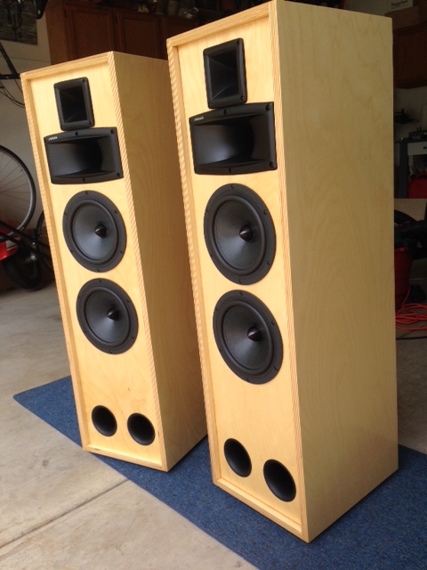
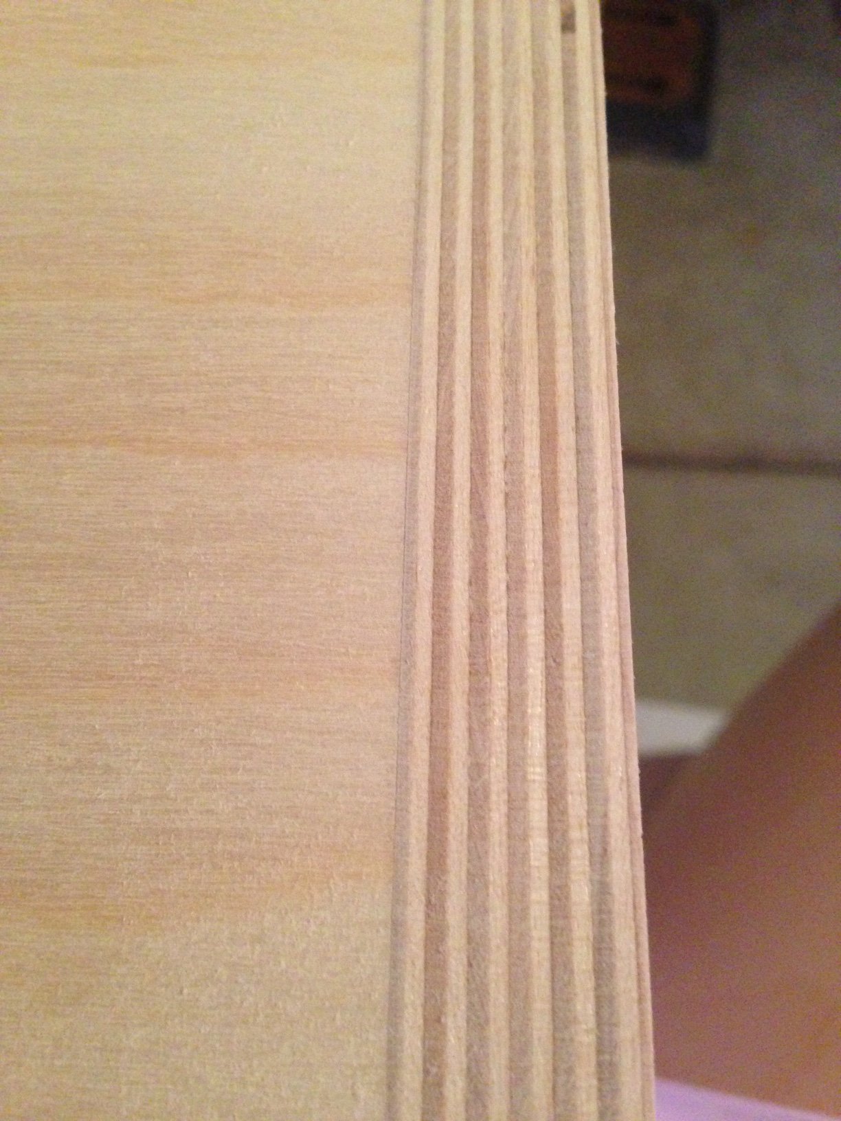
Sure. Interior dimensions for the cabinets: 11.25 W 12.75 D 42 H just under 3.5 cubic feet interior. I'll attach a picture. I built them over the summer out of baltic birch - found a nice source for it and it makes them look Klipsch-like. The two ports are supposed to tune them to about 32 Hz. The woofers are 2-8” Dayton 295-377 4 ohm. I intend to wire them in series to create an 8-ohm load. Hoping to get them to sound as good as possible and I like the idea of incorporating the T2As if I can. Thanks again.
-
I also found the tables below in an old post . . . instead of 256 ohms, I guess I'm looking for 128 ohms for Tap 1 . . . to maintain 700 Hz crossover frequency. But maybe I'm only going to get -6 db of attenuation unless something else is done in addition. (The woofers I picked for my project are Sensitivity = 93.8 dB 2.83V/1m, so it would seem that I need the whole -12db) t2a at 16 ohm driver tap attn multi impedance 4 -3 2x 32 3 -6 4x 64 2 -9 8x 128 1 -12 16x 256 t2a at 8 ohm driver tap attn multi impedance 4 -1.5 2x 16 3 -3 4x 32 2 -4.5 8x 64 1 -6 16x 128 I appreciate any advice very much.
-
Thanks Dean! I was hoping you'd see this question. Here are the specs of the driver that I'd like to use with this Type E network/T2As: Power handling: 75 watts RMS with recommended crossover of 500 Hz, 12 dB/octave slope • VCdia: 2" • Impedance: 8 ohms • Frequency response: 400-8,000 Hz • SPL: 107 dB 2.83V/1m Also, I found a very relevant post that you wrote 10 yrs ago to explain why 11 ohms swamping resistor and 21uF capacitor: "the goal is to create a somewhat constant impedance, with low pass and high pass sections somewhat equal in impedance. The design assumes the K-22-E is 11 ohms at the crossover frequency (700Hz). To get the matching high pass section, and the proper resistor value for the autoformer -- we need to know the reflected impedance with the tap we are going to use. In this case, it's tap 1, and we'll go with 256 ohms (even though it's actually a little lower than that). At this point we bang on our resistor calculator until we find the value that gives us our closest match to the impedance of our low pass section at the crossover point. Using the calculator, we discover that if we parallel an 11 ohm resistor with 256 ohms -- we come up with 10.54 ohms. 11 ohms is close enough here, and we strap it across taps 5 and 0. Now we need the correct cap value for 11 ohms at 700Hz. That value is roughly 21uF. This design presents a benign, stable load to the amp --"
-
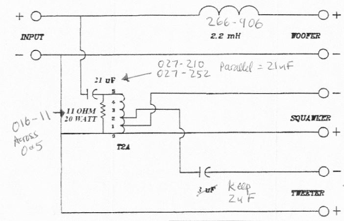
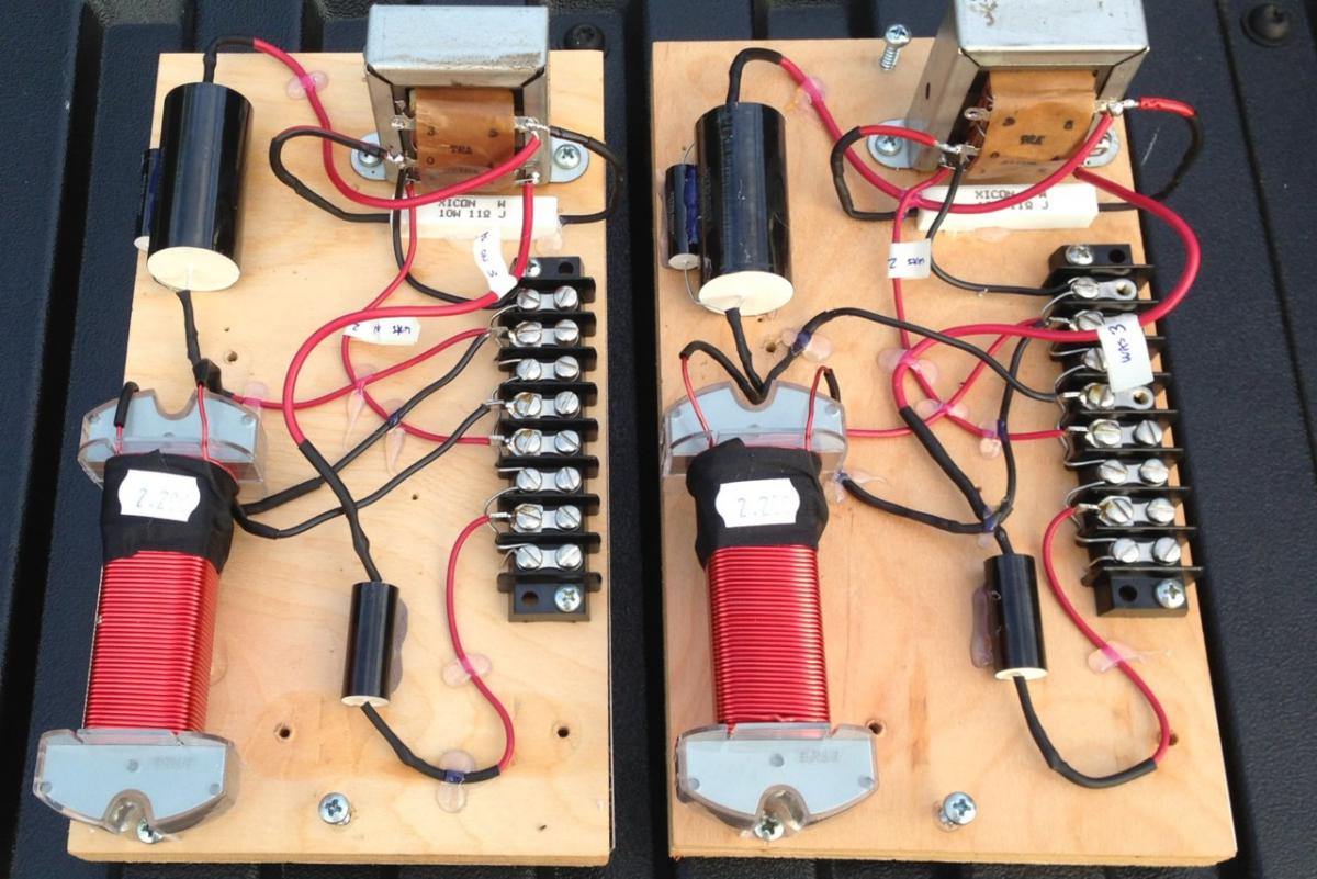
ha ha, thanks! These were stock Type E's, so here is what I did to end up at the diagram above (there is also a lot of discussion about this mod in other threads on this forum): - The woofer inductor was changed from 2.5mH to 2.2mH. I splurged on a nice ERSE inductor after a recommendation from Bruce. - The Squawker taps were changed from 2 to 1. - Tweeter connections were changed from tap 3 to 2. - The 2uF cap in front of the autoformer was changed to 21uF (I used 2 caps in parallel to get to 21uF) - An 11-ohm resistor was strapped across 0 & 5 taps.
-
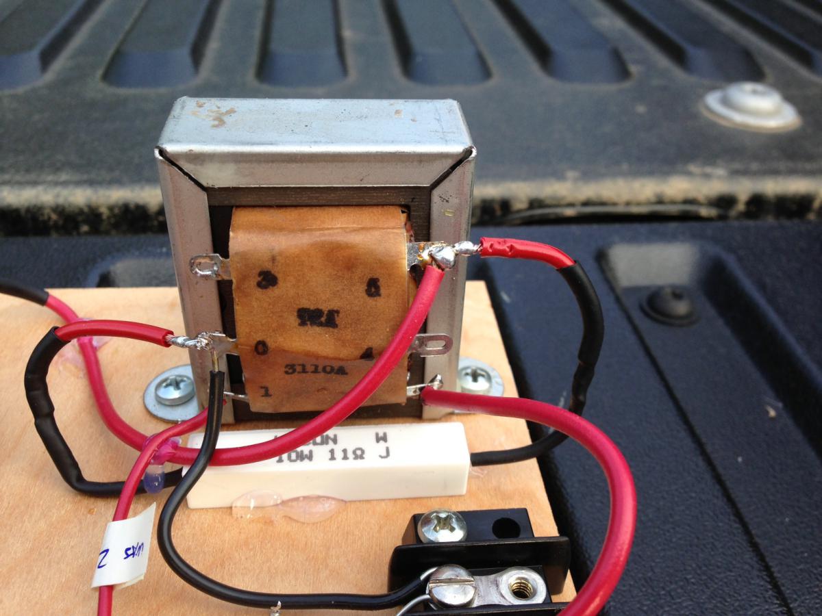
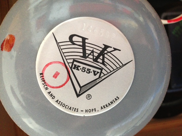
Hello, I have a question, please! About 4 mos. ago, I got brave and made changes to my Type E crossovers (schematic attached) based on what I learned on this forum, with help from several of you, and it worked out very well - holy cow, they sound tremendous in my Heresy's. I am still amazed 4 months later after much listening. I am glad I did it and I think you guys are the best Klipsch experts out there. So . . . I want to use the same modified Type E network in another horn-loaded 3-way application which has the same 700/6000 crossover frequencies. The squawker that I'm planning to use is in my new speakers is rated 8 ohms . . . I know that the K-55-V is rated at 16 ohms (however K-55-V squawkers that sound awesome with the modified Type E network test at 11 ohms with a multi-meter, disconnected). My question is: should I change something in this modified Type E network for an 8-ohm squawker? If so, what should I try? Seems like the 21uF cap or the 11 ohm resistor are what could be affected by the change of drivers from 11 ohm (or 16, or whatever a K-55-V is) to my new 8-ohm compression driver. Thanks very much for any comments. (I barely feel worthy to post on this forum so I hope you'll go easy on me.)
-
Hi, I chose a Nikon D3200 for my daughter last Christmas! It came bundled with both standard and telephoto lenses. It's been a great camera. Very flexible! Takes unbelievably-great photos. She's been able to use to learn about aperture and shutter speed combinations. It's fairly lightweight also. Anyway we like it a lot. (I borrow it!)
-
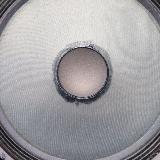
Hello. Last summer I repaired an over-excursion damaged K-22-E with the Parts Express glue mentioned above (340-076). While this glue looks like wood glue, it dries clear and "rubbery" and stays somewhat flexible. I thought it made a good repair - certainly glued the fibers down in my case - but it's far from invisible. Anyway I decided to upgrade to new woofers. Just thought this might help others if they are deciding between glues. Good luck!
-
I have the debut carbon and like it a lot. The anti-skate mechanism is kind of interesting - small weight on what looks like fishing line, run through a wire ring. It's manual so you have to do everything but I don't mind that. good luck!
-
"cap them" means, simply, replace the 40-yr old capacitors that are in your crossovers with new ones that will bring everything back into spec. I did a lot of reading about my Heresy crossovers and it's commonly believed that capacitors drift out of spec over time and need to be replaced. It was an easy job if you are able to solder. I used these caps in my Heresy I Type Es as a low-cost alternative: Dayton Audio PMPC-2.0 2.0uF 250V Precision Audio Capacitor https://www.parts-express.com/dayton-audio-pmpc-20-20uf-250v-precision-audio-capacitor--027-214 Model: PMPC-2.0|Part # 027-214 I hope that helps and good luck! That's very cool that you kept those speakers all these years.
-
Just for fun, in case you haven't seen it, I'll attach a brochure that I found on the Heresy I. I think this is a very cool document! It makes the point that Heresy's were not designed for low bass response (only 50 Hz) and gives a really good description of the design. I've really enjoyed having these speakers. Heresy I Flyer.pdf
-
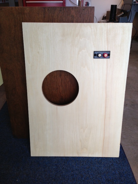
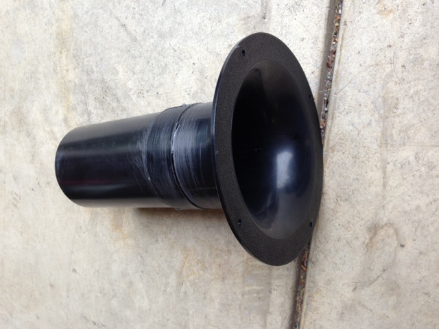
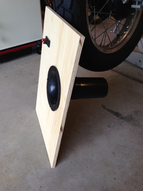
Sure - but I have to confess that in addition to the ports and improved sealing, I followed John Albright's crossover mods. (I also dropped in some new woofers and damped the aluminum horns.) So I am commenting on a set of changes actually. Maybe I'm not in the best position to comment on the effect of just ports because I changed other things too. Anyway, I'll paste pics of the ports that I picked and the new backs. They are 3" ports from Parts Express, with a flare on the outside. I had to think about where to put them because as you know Heresy cabinets are really packed full of drivers but I squeezed them in - just couldn't go as low as I'd have liked. I got advice from Matt at Parts Express relative to the diameter and length of the port tubes. I am really enjoying the new sound! It's very full - much more than before - and I love how the mid and highs come through so clear and seem to sparkle. Vocals seem astonishingly clear, real sounding and warmer than before the mods. At the moment I'm using a vintage amp (Realistic STA-90) and I can leave the bass and treble controls at neutral and there is plenty of clean bass that "thumps" and sounds very solid and sometimes "growly". I can hear individual bass notes cleanly. In rock music I can hear what the bass player is playing - the riffs etc. are clear. I don't know if it's "muddy" or not, honestly, but I think it's fun to hear these speakers in a new way that's for sure. I can listen for long periods of time now without any fatigue. Amazing but the changes made the horns sound better somehow. Great imaging. The vocals really ride in a nice place now and I can hear individual instruments better. So clear it's truly amazing! I think that's what I notice the most. The plywood was $5 at Menards and the ports were cheap and easily reversible in 10 minutes.
-
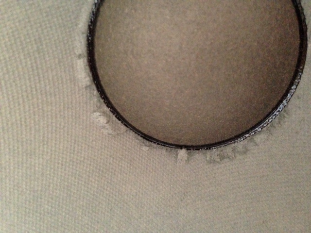
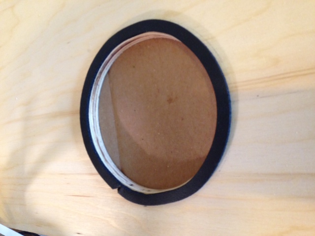
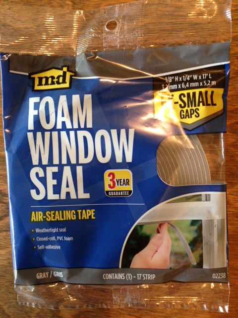
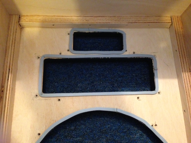
Hello! Well, I recently got a lot of help on this forum for some Heresy I crossover improvements, and I thought I'd share the link just in case you are thinking about some options for your project. https://community.klipsch.com/index.php?/topic/45977-heresy-speaker-balance-question/ I think this is an awesome father-and-son project! I learned a lot from "refurbishing" my Heresy's. Like a lot of people I guess, I found that my Heresy's, which are the same as yours, sounded overly bright and I tried really hard to adjust to them, but finally decided to make some changes which helped a lot. There are many Heresy mod threads out there. Besides the crossovers I made a few other improvements which were fun to experiment with and hear the impact. For example, I was surprised that there was no gasket material of any kind between the drivers and the baffle, or to seal the back. I found some inexpensive narrow adhesive weatherstripping that worked great so I included those pictures here too. I also made alternate backs from plywood and added ports . . . to see if it would improve the low end and kept the originals so I can go back to sealed boxes easily. Heresy's are fun to experiment with. Good luck!
-
Oops the attachment didn't make it.
-
Back in the 70s . . . I remember hifi stores with rows of speakers that you could test. This album was one of the ones that was known for being good for testing. I didn't see it mentioned so felt obligated to contribute!
-
Thank you for all the help! I made all of John Albright's mods today . . . used two caps in parallel to get to 21uF, also used the Erse Super Q that Bruce suggested to drop to 2.2 mH. I decided to put jumpers between my resistor (which I glued to the board) and 0 & 5 taps on the autotransformer. I did my best to keep it neat but I'm sure the soldering could be better. I was concerned about damaging the T2A by applying the heat it would have taken to flow the solder better so I just made sure that it stuck solid and left it. Seemed like the wax paper stuff wanted to melt. Anyway - the speakers certainly sound more 'full'. Vocals are really tremendous; even astonishing - they stand out more! It's difficult to describe. The sound is more live. Stereo imaging seems better. There is more depth to the sound. Smoother with great detail. I really like the change. It was apparent immediately when I first listened. Big improvement! You guys rock.
-
Thanks again Bruce. That's a good point. It'll be a new crossover except for the T2A. Is the effect of changing from 2.5 mH to 2.2 mH in this position to make the woofer less attenuated (ie louder )in the balance?. If so that could be good . . . Thanks!!
-
Sorry one more post if anyone is out there for comment: I could put these together in parallel to get 21uF . . . Dayton Audio PMPC-1.0 1.0uF 250V Precision Audio Capacitor Model: PMPC-1.0|Part # 027-210 Dayton Audio PMPC-20 20uF 250V Precision Audio Capacitor Model: PMPC-20|Part # 027-252 Also, I noticed that the inductor for the woofer is suggested to go from 2.5mH stock to 2.2 . . . those are more expensive - is that a significant change, absolutely necessary? I found this inductor which is 2.2 and not too bad - would it be acceptable and worthwhile? https://www.parts-express.com/jantzen-audio-22mh-20-awg-p-core-inductor-crossover-coil--255-130 Thanks again for any comments! It's been very helpful and I've learned a lot here.
-
Thanks Bruce (and Pio). That helps a lot to see an example. P.E. tells me that 027-436 20uF is close enough to 21uF to work in this mod, and that 016-11 is ok to use at 10 watts (instead of 20 watts) so I'm planning to give this a try using those parts unless anyone has other advice. My Heresy's are I's. I really love them; they just need a little help I think.
-
Thanks very much!! Post #35 in the linked thread does look like a very good, well-thought-out solution. I'd like to try that one. I really appreciate all the knowledge on this forum. I wanted to get the resistor and capacitors for this at Parts Express, but having some trouble - Parts Express has this resistor but it's rated 10 Watts (not 20 as indicated in John Albright's mod). http://www.parts-express.com/11-ohm-10w-resistor-wire-wound-5-tolerance--016-11 My amps are 35 watts and around 70 watts. I also can't find a 21 uF cap at P.E., but they do have a 20uF 250V one: http://www.parts-express.com/dayton-audio-dmpc-20-20uf-250v-polypropylene-capacitor--027-436 Are those close enough or is it critical to get the exact values? Also, I wonder if the resistor is strapped across 0 and 5 directly on the side of the autoformer. I can't seem to find a picture of the mod done on an actual cross over. I suppose I could install the resistor between the leads that attach to 0 and 5, instead of across those taps directly. Thanks again for all the help.
-
The 3rd point in post #2 of this thread seems very interesting - simply attenuate the tweeter this way. I wonder if doing this could have any adverse consequences relative to crossover frequency or impedance load. It didn't get a lot of discussion back in 2004! I'm curious if anybody else has tried it and how they liked the change. .
.jpg.b171e38f51fbe90d1e3d9ab65a7dd713.jpg)
.jpg.825f279a2c806be0f534fa59310ac3c4.jpg)
.jpg.c0d25ab419f724de2274af2aba8068c9.jpg)
.jpg.a40e6f38b93812032db8bbdb73d9c9d1.jpg)