ToolShedAmps
-
Posts
207 -
Joined
Content Type
Forums
Events
Gallery
Everything posted by ToolShedAmps
-

Henry Scott Yocum Memorial Amplifier Build
ToolShedAmps replied to ToolShedAmps's topic in Talkin' Tubes
Thank you very much. Merry Christmas! -
Henry Scott Yocum Memorial Amplifier Build
ToolShedAmps replied to ToolShedAmps's topic in Talkin' Tubes
Thanks Mike! The Yocum family should have it either today or Monday at the latest. Perhaps they will listen to some holiday music through it. Thanks for following along.. Cheers All! Matt.- 80 replies
-
- 2
-

-
- 2a3
- single-ended
- (and 1 more)
-
Henry Scott Yocum Memorial Amplifier Build
ToolShedAmps replied to ToolShedAmps's topic in Talkin' Tubes

- 80 replies
-
- 7
-
-

-
- 2a3
- single-ended
- (and 1 more)
-
Henry Scott Yocum Memorial Amplifier Build
ToolShedAmps replied to ToolShedAmps's topic in Talkin' Tubes
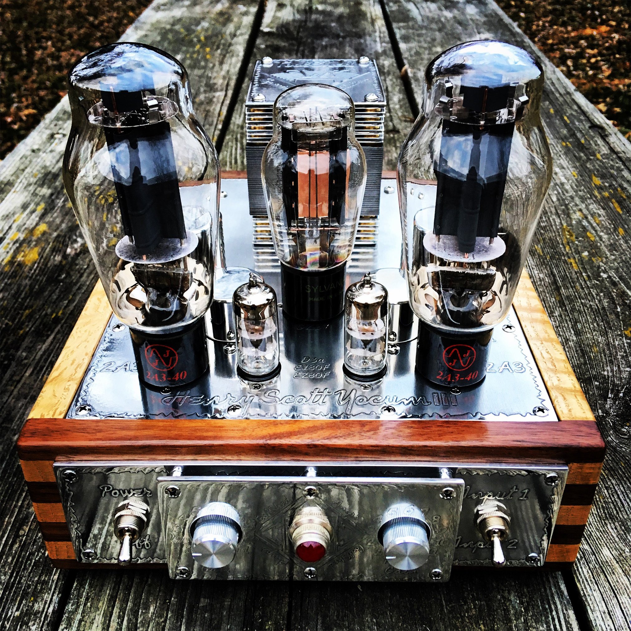
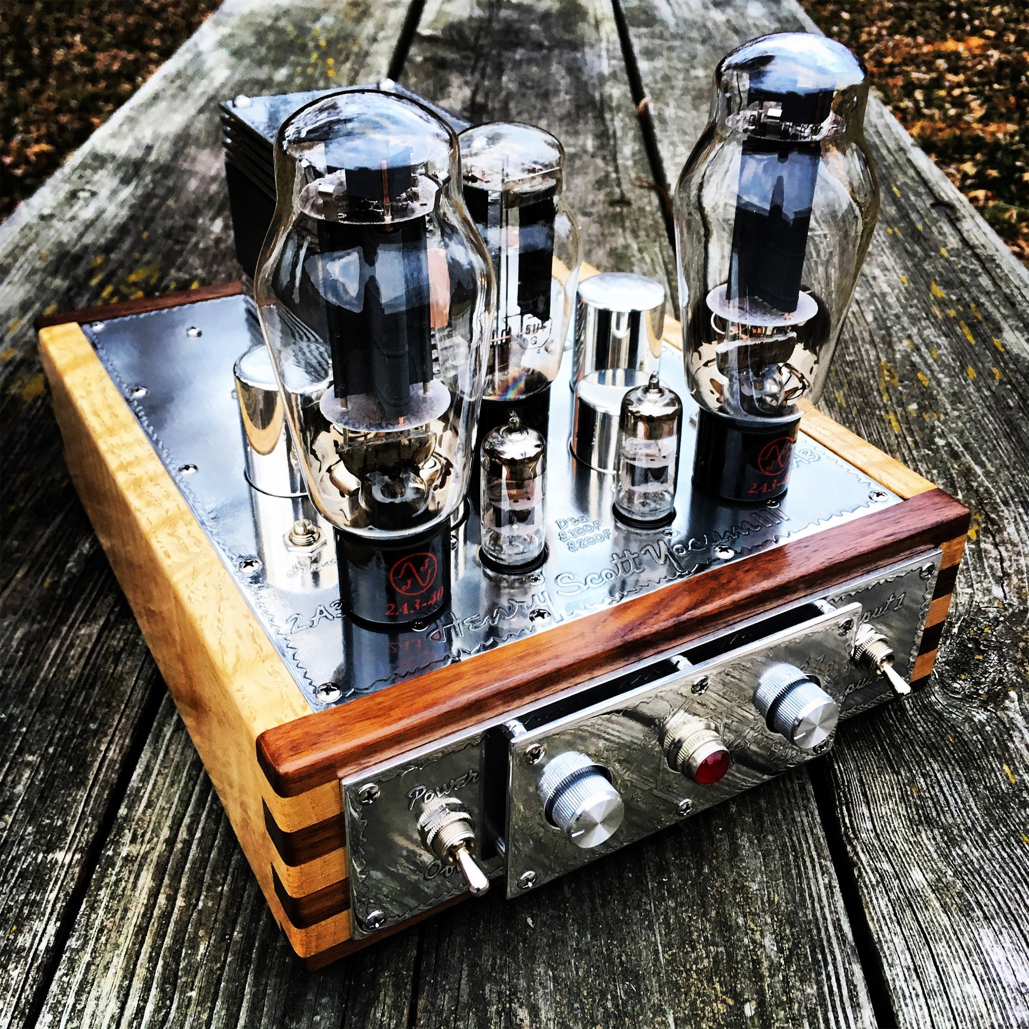
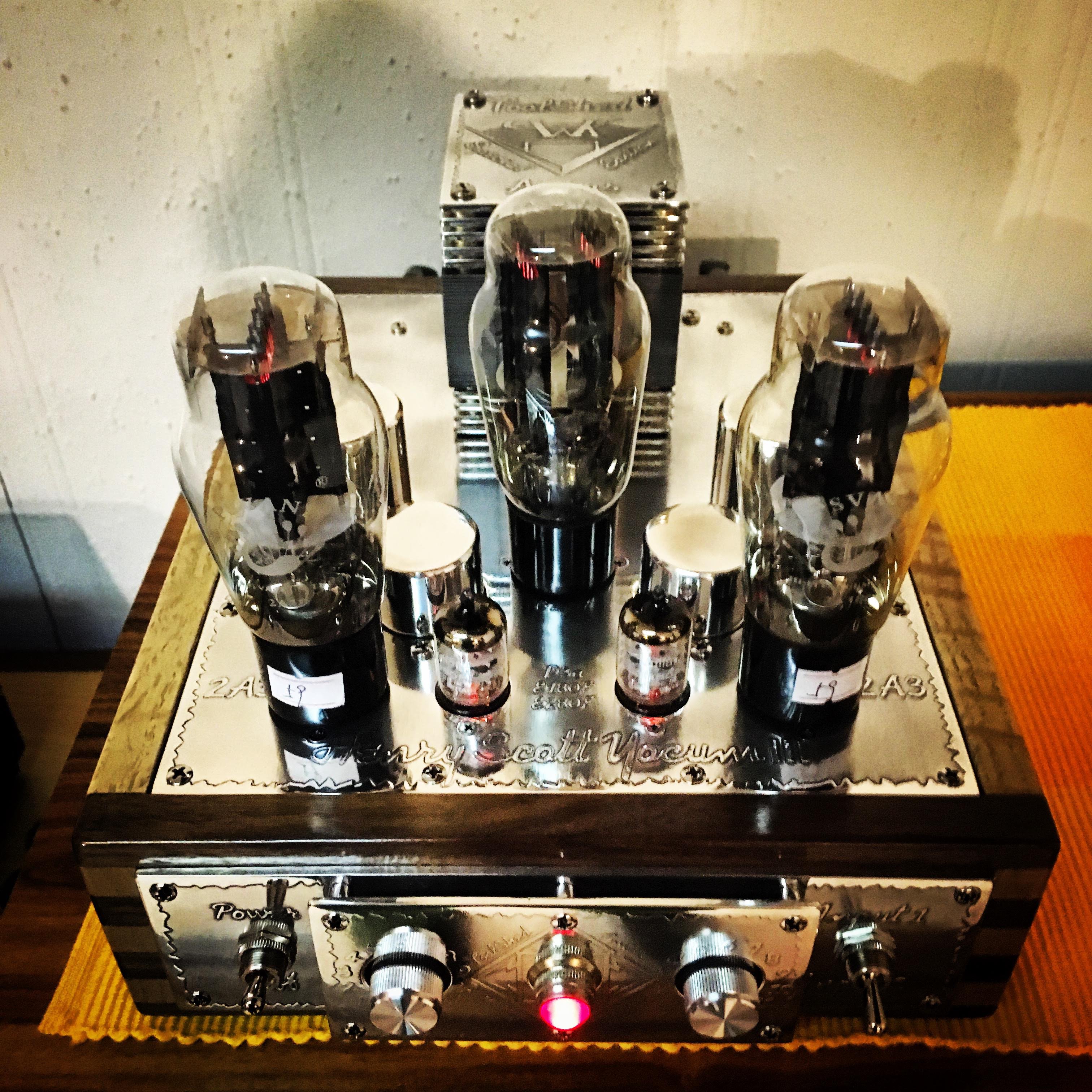
Here are a couple of pictures of the finished amplifier.........
- 80 replies
-
- 6
-
-
-
- 2a3
- single-ended
- (and 1 more)
-
Henry Scott Yocum Memorial Amplifier Build
ToolShedAmps replied to ToolShedAmps's topic in Talkin' Tubes
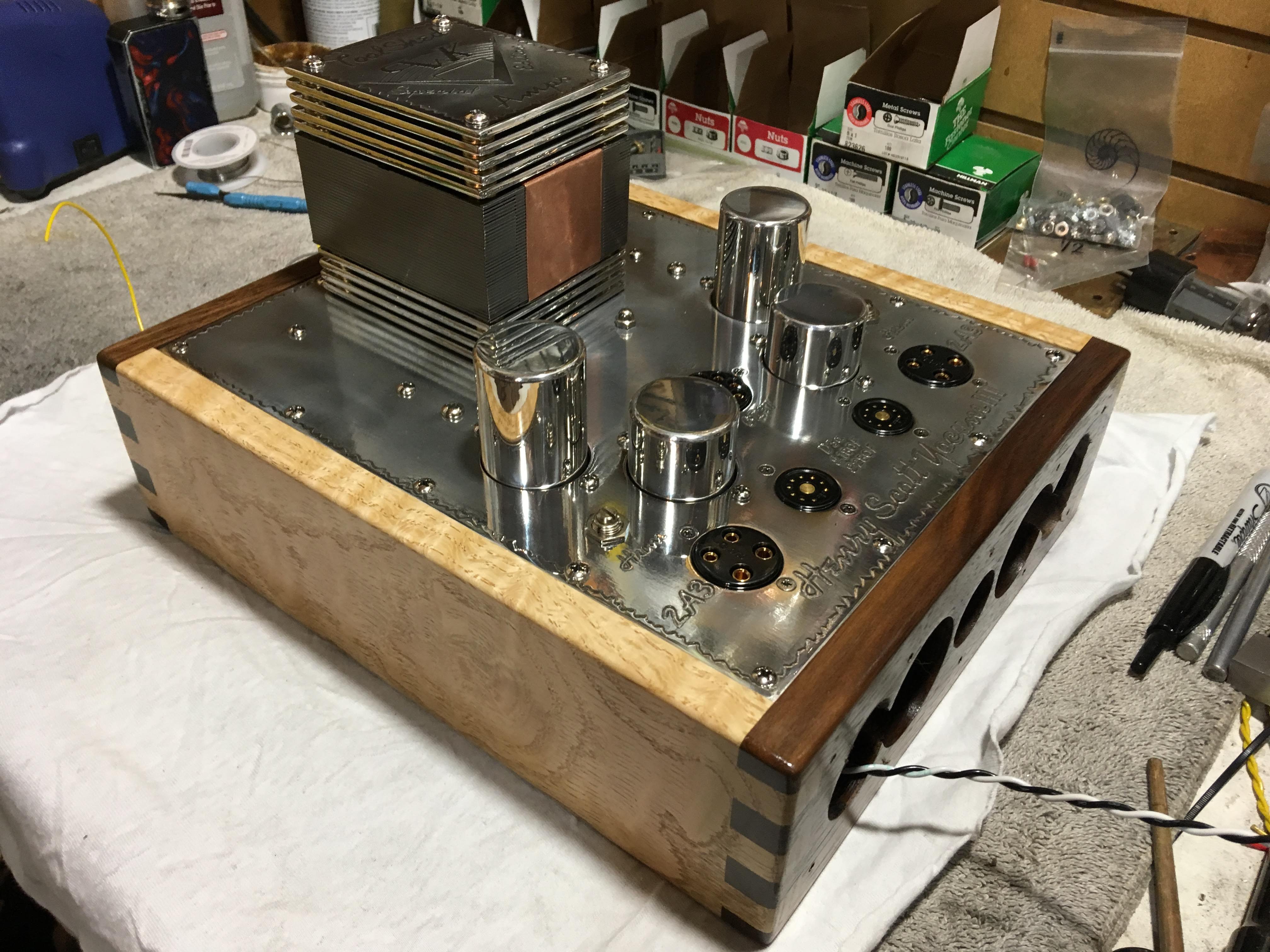
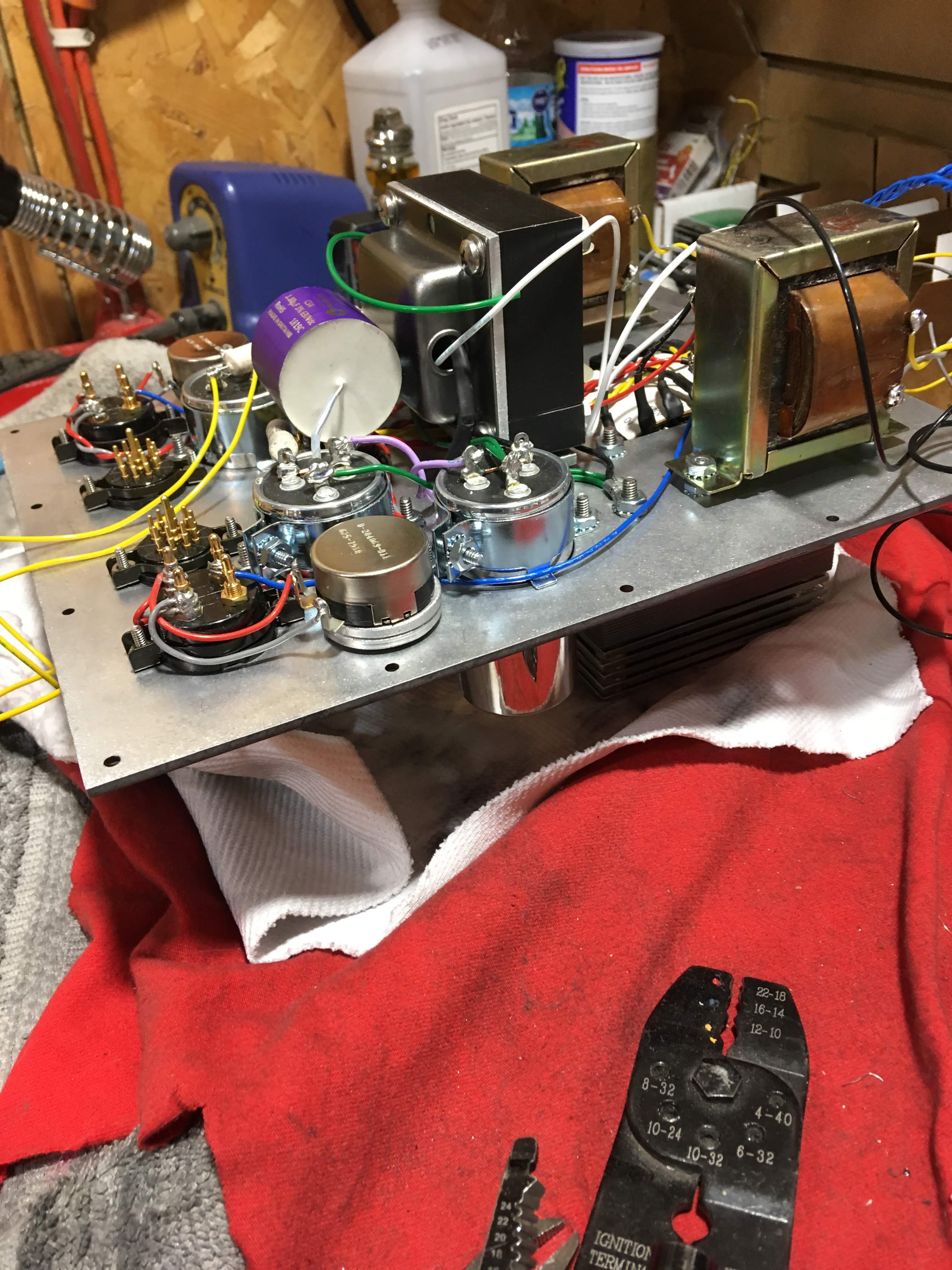
Top-side of the amp prior to wiring and installing the front and rear plates. The last photo's I'll post will be the ones I take today after the bottom plate is installed (post burn-in) in preparation for shipping this evening. I've really enjoyed my time listening to this amplifier during burn-in and can say without reservation that my Cornwall's have never sounded so good. At least until the next one burns-in.....
- 80 replies
-
- 4
-
-
-
- 2a3
- single-ended
- (and 1 more)
-
Henry Scott Yocum Memorial Amplifier Build
ToolShedAmps replied to ToolShedAmps's topic in Talkin' Tubes
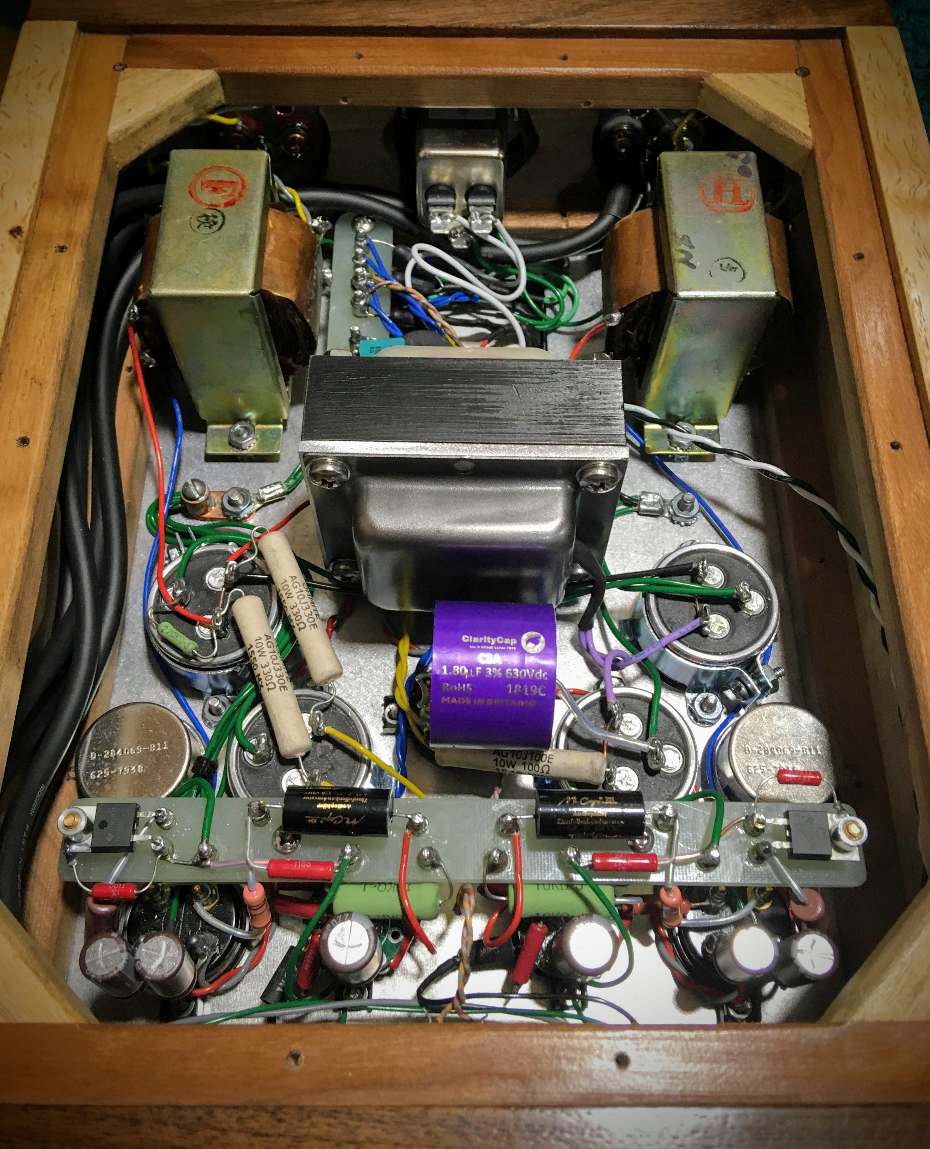
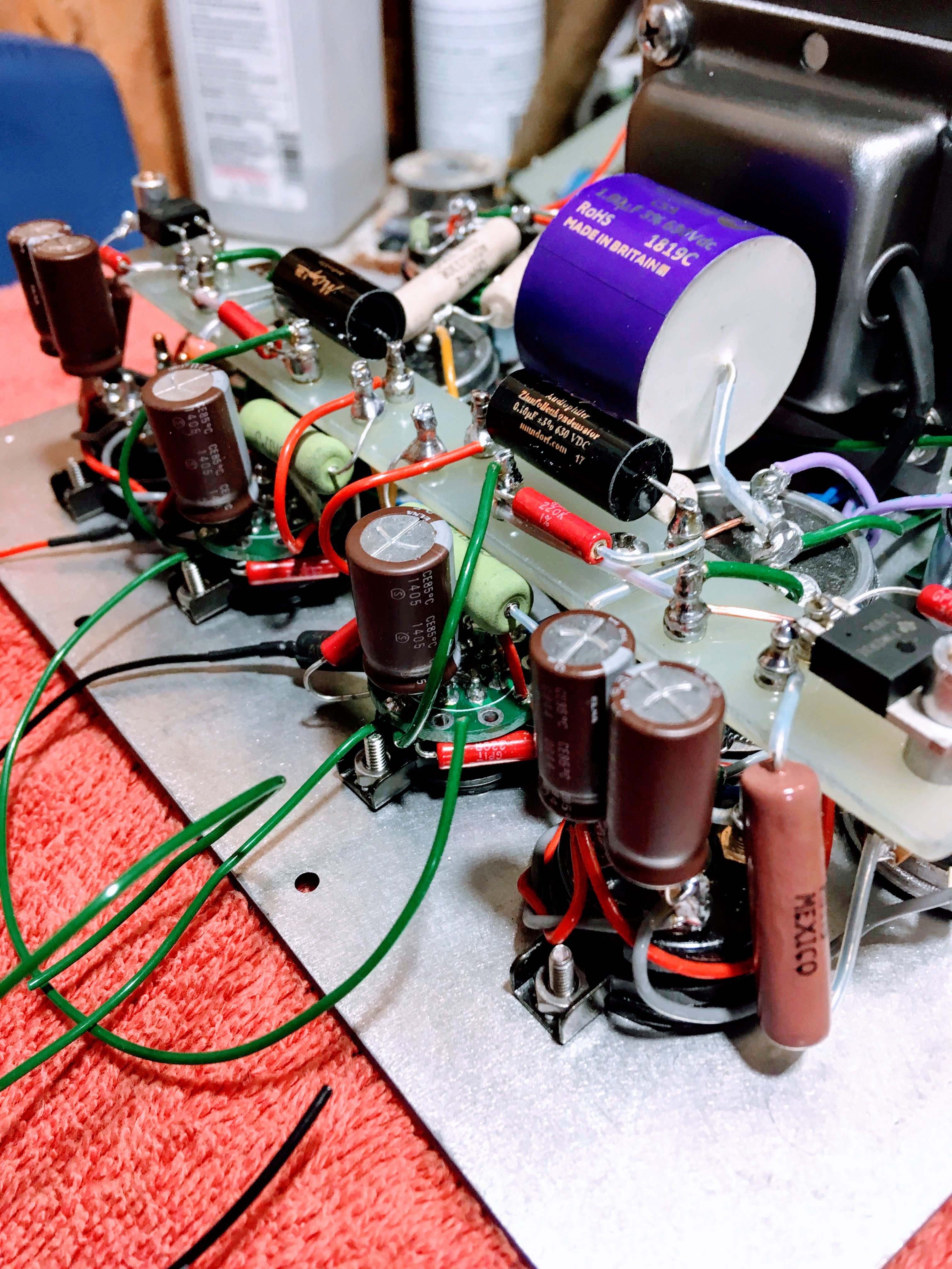
Here is the plate (gut-shot) mounted in the wood base...... as you can see, enough room to work but not much else. ToolShed Amplifiers are only as large as they have to be. I've designed the amplifier to have the coupling capacitors easily accessible should customers feel the need to "roll" those too....
- 80 replies
-
- 4
-
-
- 2a3
- single-ended
- (and 1 more)
-
Henry Scott Yocum Memorial Amplifier Build
ToolShedAmps replied to ToolShedAmps's topic in Talkin' Tubes
Without boring y'all with the details, here is the completed circuit. With the top-plate finished, it can be installed in it's wood base.
- 80 replies
-
- 4
-
-
- 2a3
- single-ended
- (and 1 more)
-
Henry Scott Yocum Memorial Amplifier Build
ToolShedAmps replied to ToolShedAmps's topic in Talkin' Tubes
- 80 replies
-
- 1
-
-
- 2a3
- single-ended
- (and 1 more)
-
Henry Scott Yocum Memorial Amplifier Build
ToolShedAmps replied to ToolShedAmps's topic in Talkin' Tubes
As much wiring is completed as possible prior to building the "turret-board" that is suspended above the front section of the amplifier. This turret board is where all of the circuit connections are made to the devices that are soldered to the tube sockets. I build mine out of 1/8" fiberglass board and individually "swage" each turret using a press I built for this purpose. Doing this rather than buying "tag strips" or pre-made turret boards allows me to design the layout and connection points EXACTLY where I want them with no waste. A pic of the board layout I developed for Scott's amp (and all Euphoria 2a3's coming up) will be attached to the next post...... this one is yelling at me about max file size... As I sit here typing, I'm amazed at the SQ of this amplifier.... another bonus, although I designed this amplifier to maximize the sound quality of the 2a3 output tube (my favorite operating points using a 5K primary OT), by dropping in a 5R4GY rectifier, this amp is perfectly safe for use with the "45" output tube. It sounds glorious on this last day of burn-in driving my Cornwall 3's with a very, very old pair of engraved-base Philco 45's.- 80 replies
-
- 2
-
-
- 2a3
- single-ended
- (and 1 more)
-
Henry Scott Yocum Memorial Amplifier Build
ToolShedAmps replied to ToolShedAmps's topic in Talkin' Tubes
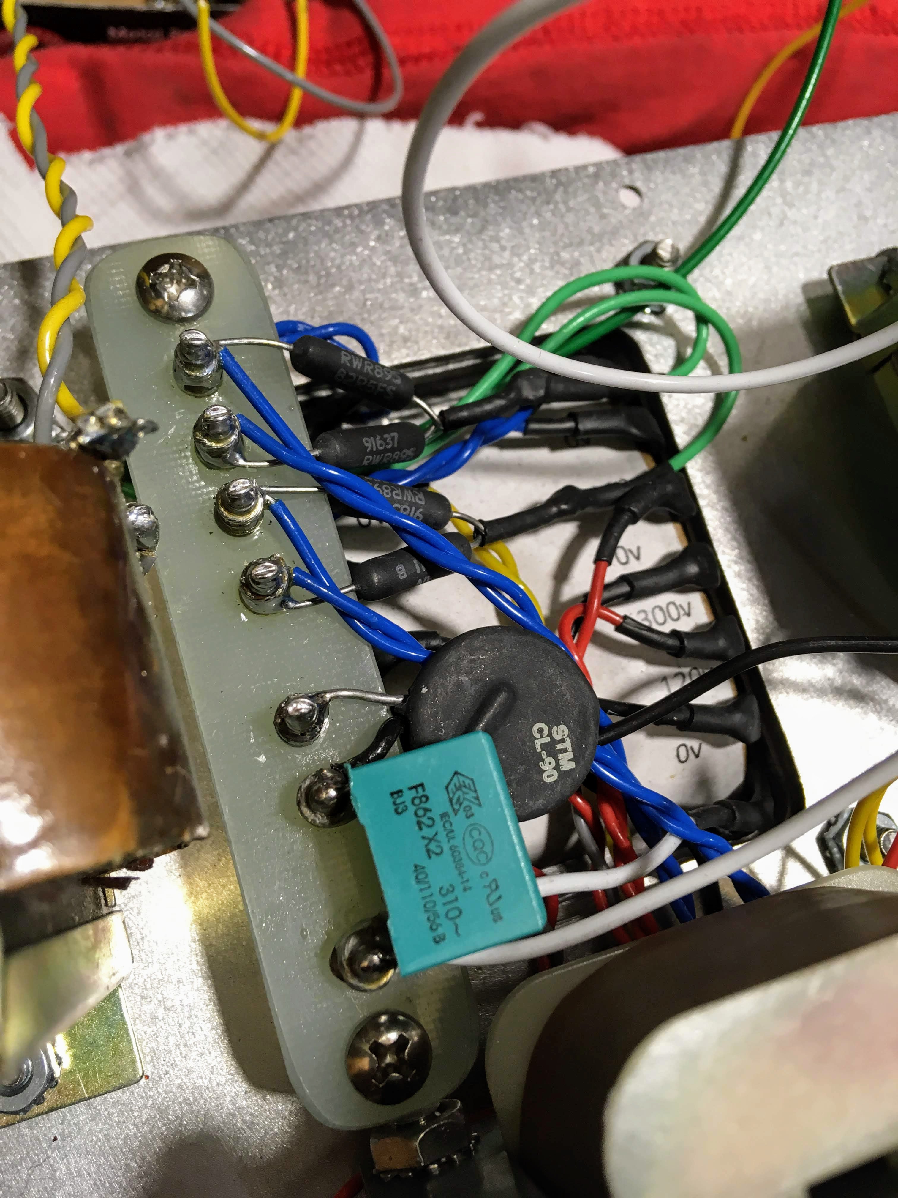
After some deliberation, and since this amplifier has no headphone output, I ultimately decided that the slight lowering of the noise-floor by using DC heating on the driver tubes wasn't worth the sonic trade-off, and, since this custom power tranny has separate 6.3v windings (one for each channel) I used AC heating with virtual center taps as per usual. This pic shows how I typically leverage the space below the power transformer to mount connection points for power supply wiring/DC rectification (when necessary). In the pic you can also easily see both the "slow-start" MOV and Class X "pop-stop" capacitor as typical on amplifiers using a directly-heated rectifier.
- 80 replies
-
- 3
-
-
- 2a3
- single-ended
- (and 1 more)
-
Henry Scott Yocum Memorial Amplifier Build
ToolShedAmps replied to ToolShedAmps's topic in Talkin' Tubes
Thanks Jimbo! As to the question, that's entirely up to Austin and the rest of Scott's family. However, there should be a few more of this version of the Euphoria floating around out there by the pilgrimage. -
Henry Scott Yocum Memorial Amplifier Build
ToolShedAmps replied to ToolShedAmps's topic in Talkin' Tubes
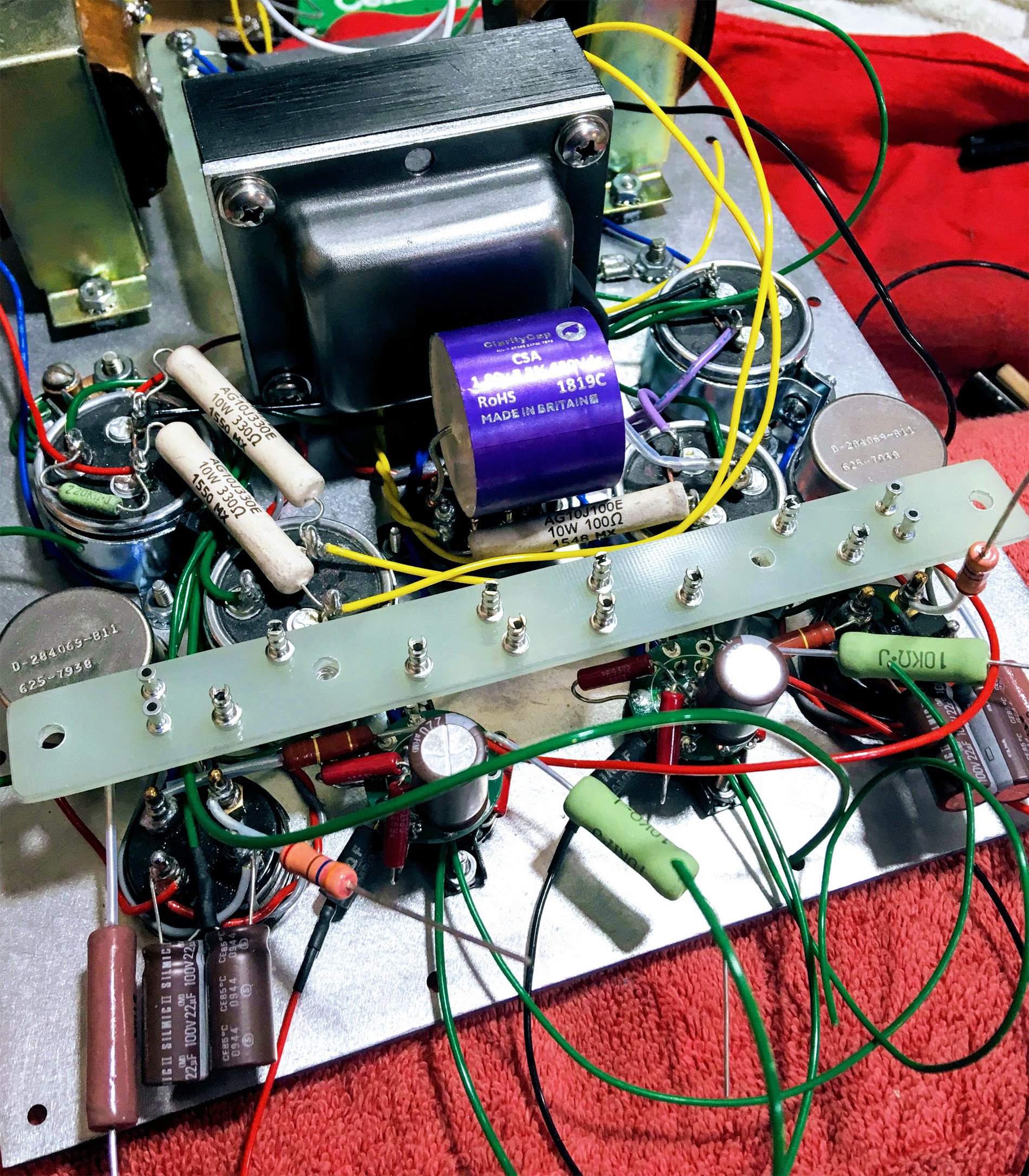
One more pic for today, this one provides context in terms of what the physical relationship of the parts look like installed on the top-plate. Here you can clearly see the giant Transcendar Choke as well as the vintage Tamura output transformers. Also, you can see the spacers that I used between the hum pots and the top-plate to lower the profile of the trimmers poking through the top. I make these out of the cut-outs from the top-plate itself.
- 80 replies
-
- 3
-
-
- 2a3
- single-ended
- (and 1 more)
-
Henry Scott Yocum Memorial Amplifier Build
ToolShedAmps replied to ToolShedAmps's topic in Talkin' Tubes
The power supply is always wired first as it occupies the majority of space in these single-ended amplifiers. The reality is that the PS is IN the audio circuit, therefore as much attention to detail spent laying out the wire paths directly correlate to how low the noise floor is in the finished amplifier. Proper grounding methodology is an absolute must. Here is a pic of some of the wiring in-process.... Here it's easy to see the heater wiring with the corresponding "hum" pot, and it's proximity to the power tube socket. I've engineered this amplifier so tightly that there is very little room for error.
- 80 replies
-
- 2
-
-
- 2a3
- single-ended
- (and 1 more)
-
Henry Scott Yocum Memorial Amplifier Build
ToolShedAmps replied to ToolShedAmps's topic in Talkin' Tubes
I then use teflon-jacketed 18-20ga. tin-plated copper wire for all of the power connections. This is the last step before populating the top-plate with all of the hardware, transformers, tube sockets, etc......
- 80 replies
-
- 2
-
-
- 2a3
- single-ended
- (and 1 more)
-
Henry Scott Yocum Memorial Amplifier Build
ToolShedAmps replied to ToolShedAmps's topic in Talkin' Tubes
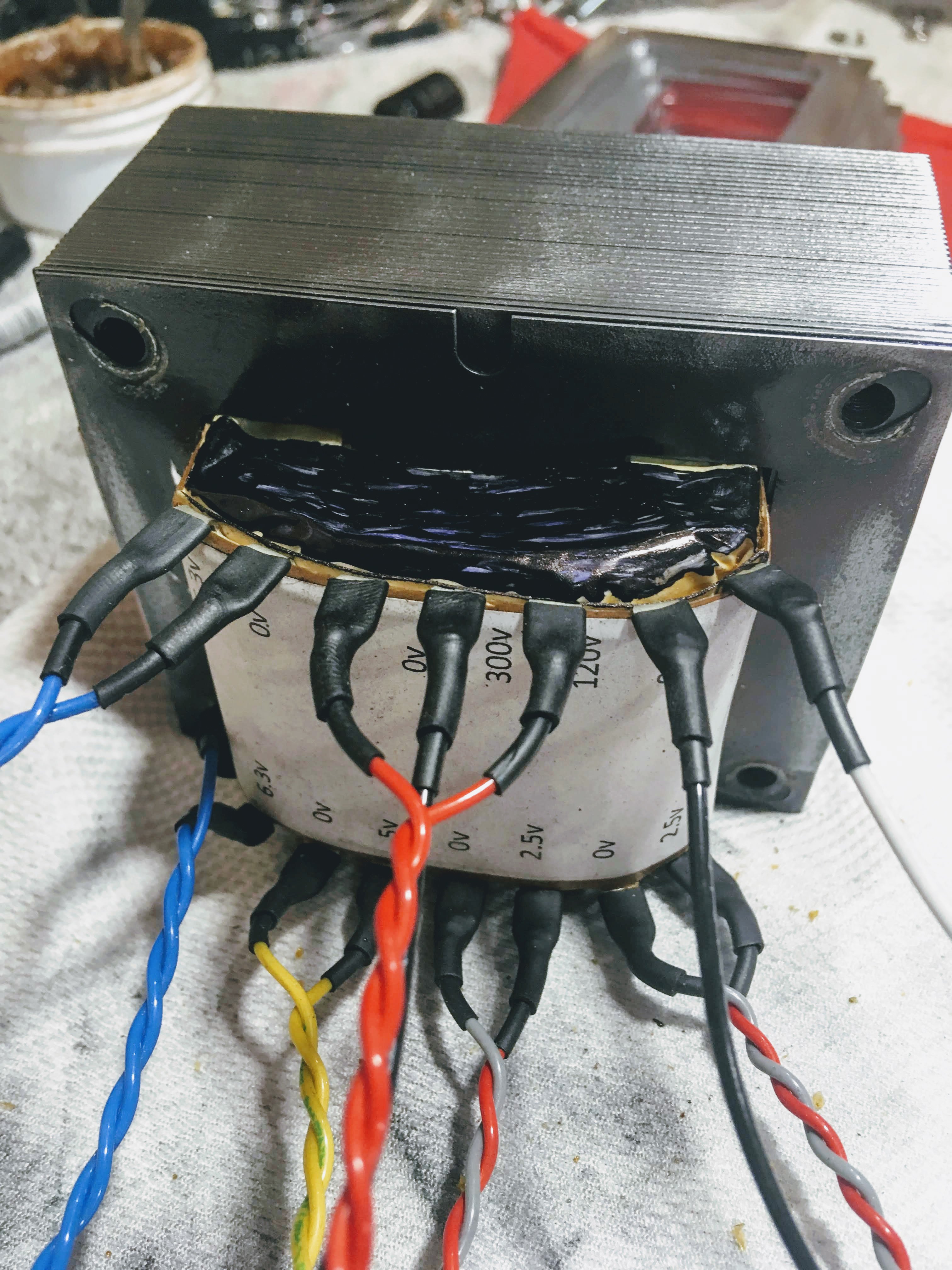
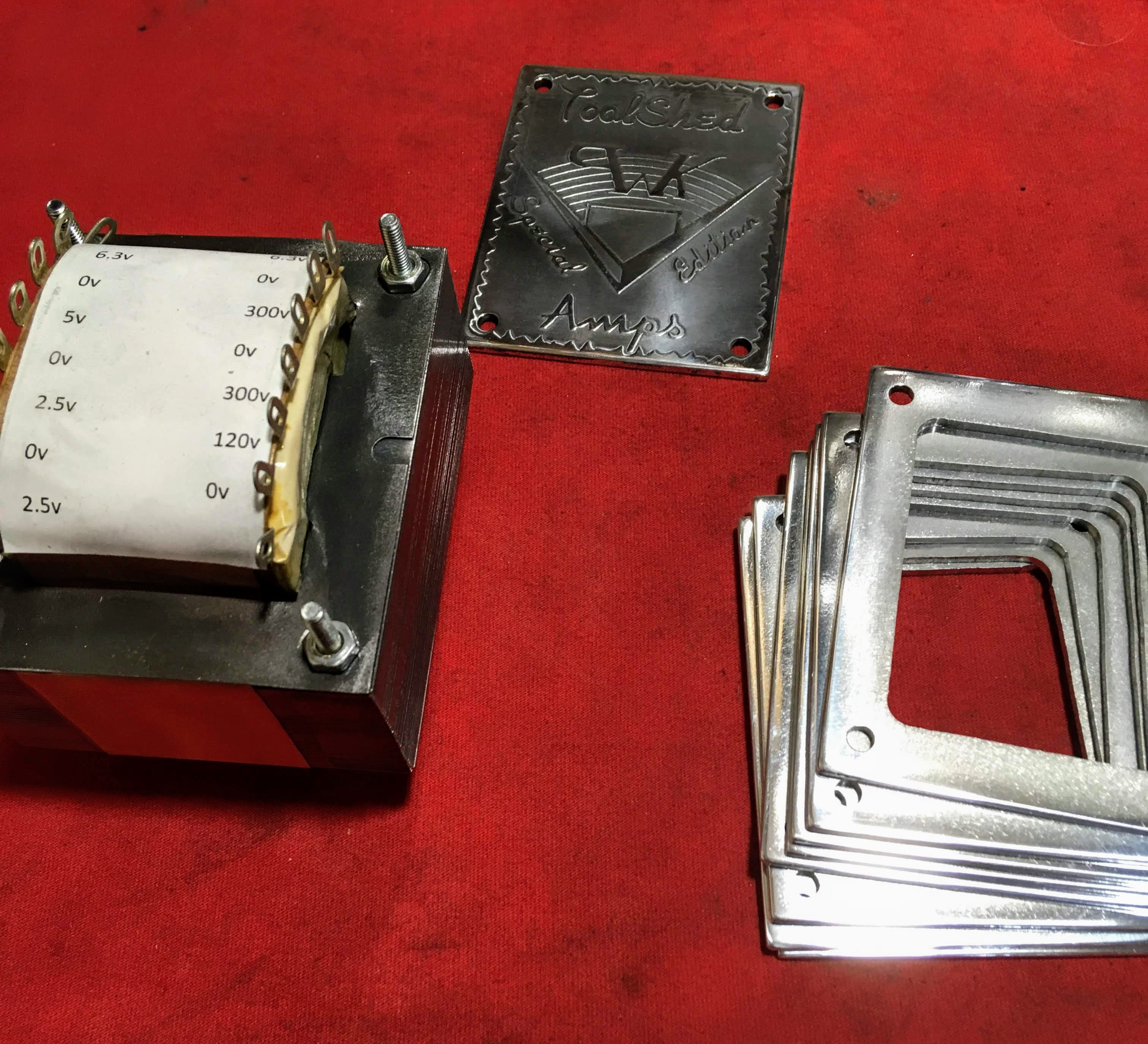
A bit about power transformers.... my method of cleaning off the poorly applied varnish (usually dipped and allowed to run off) or epoxy is with wire wheels as these do not disturb the varnish that has seeped into the transformer laminations. After cleaning I re-coat the transformer with clear, High-Temp automotive enamel. This coating is designed to protect engine parts and will certainly suffice to protect the power transformer. Here is a pic of Scott's power transformer with parts to assemble it. My preference is for "drop-through" transformers with solder lugs (either Hashimoto, or in this case a custom unit wound for me) as opposed to up-right transformers with flying leads.
- 80 replies
-
- 2
-
-
- 2a3
- single-ended
- (and 1 more)
-
Henry Scott Yocum Memorial Amplifier Build
ToolShedAmps replied to ToolShedAmps's topic in Talkin' Tubes
Howdy all! Happy Holidays! So, as many of you know, the "Memorial" amp is finished and "burning-in" as I type this........ sorry for the delay in posting to this thread. Much of life has gotten in the way. The next couple of installments will be an explanation of how it got to this point, with some detailed photos of my method of wiring/building. As for how it sounds, I'm certain that Scott would have loved it.
- 80 replies
-
- 7
-
-
-
- 2a3
- single-ended
- (and 1 more)
-
Henry Scott Yocum Memorial Amplifier Build
ToolShedAmps replied to ToolShedAmps's topic in Talkin' Tubes
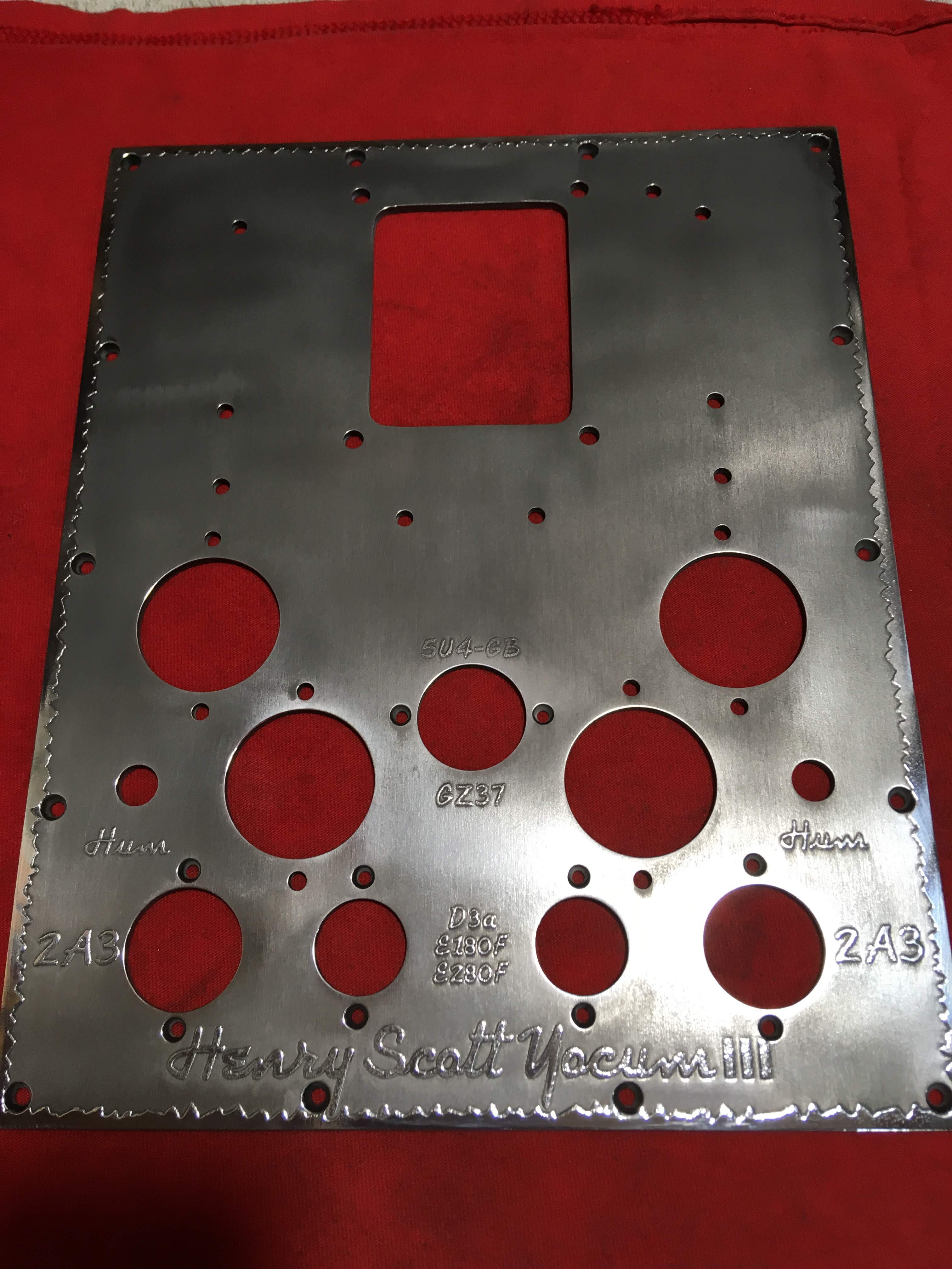
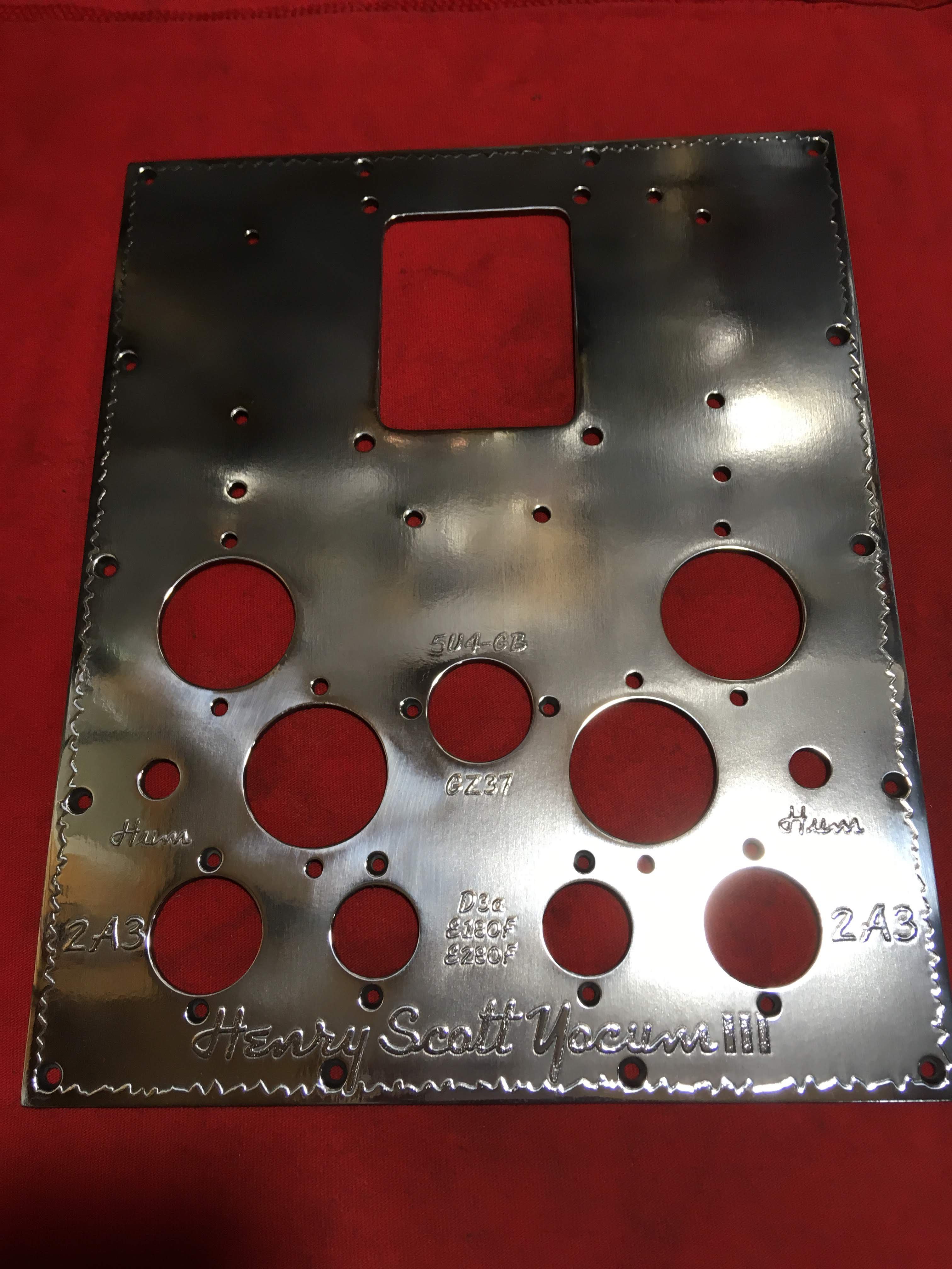
Howdy all! After the long weekend I thought I'd just pop in and post some progress pics of the polishing of the 6061 Aluminum plates for the Memorial Amp I polish everything on a polishing wheel consisting of a 10" sewn cotton wheel mounted on an old 1750 rpm 3/4 hp electric motor. I exclusively use "RED" polishing compound for the 1st two polishing sessions for each plate, followed by one polishing session using the "WHITE" or Diamond compound....... this takes some time, be patient. The 1st pic is of the top-plate after just the 1st polishing session. 2nd pic is after the 2nd polishing session.... wipe the plate down with an old, old, old cotton t-shirt dipped in fresh lacquer thinner between sessions. There will be a lot of built-up slurry of polishing compound and aluminum that has to be removed between sessions.
- 80 replies
-
- 4
-
-
- 2a3
- single-ended
- (and 1 more)
-
Henry Scott Yocum Memorial Amplifier Build
ToolShedAmps replied to ToolShedAmps's topic in Talkin' Tubes
I used to use Ferric Chloride to etch the copper and brass plates (it doesn't work on aluminum), and disposal of the used medium was difficult. I had to wait for the chem. disposal window at the local municipal yard which is only twice a year. Luckily this method doesn't require any unusual disposal method. Matt. -
Henry Scott Yocum Memorial Amplifier Build
ToolShedAmps replied to ToolShedAmps's topic in Talkin' Tubes
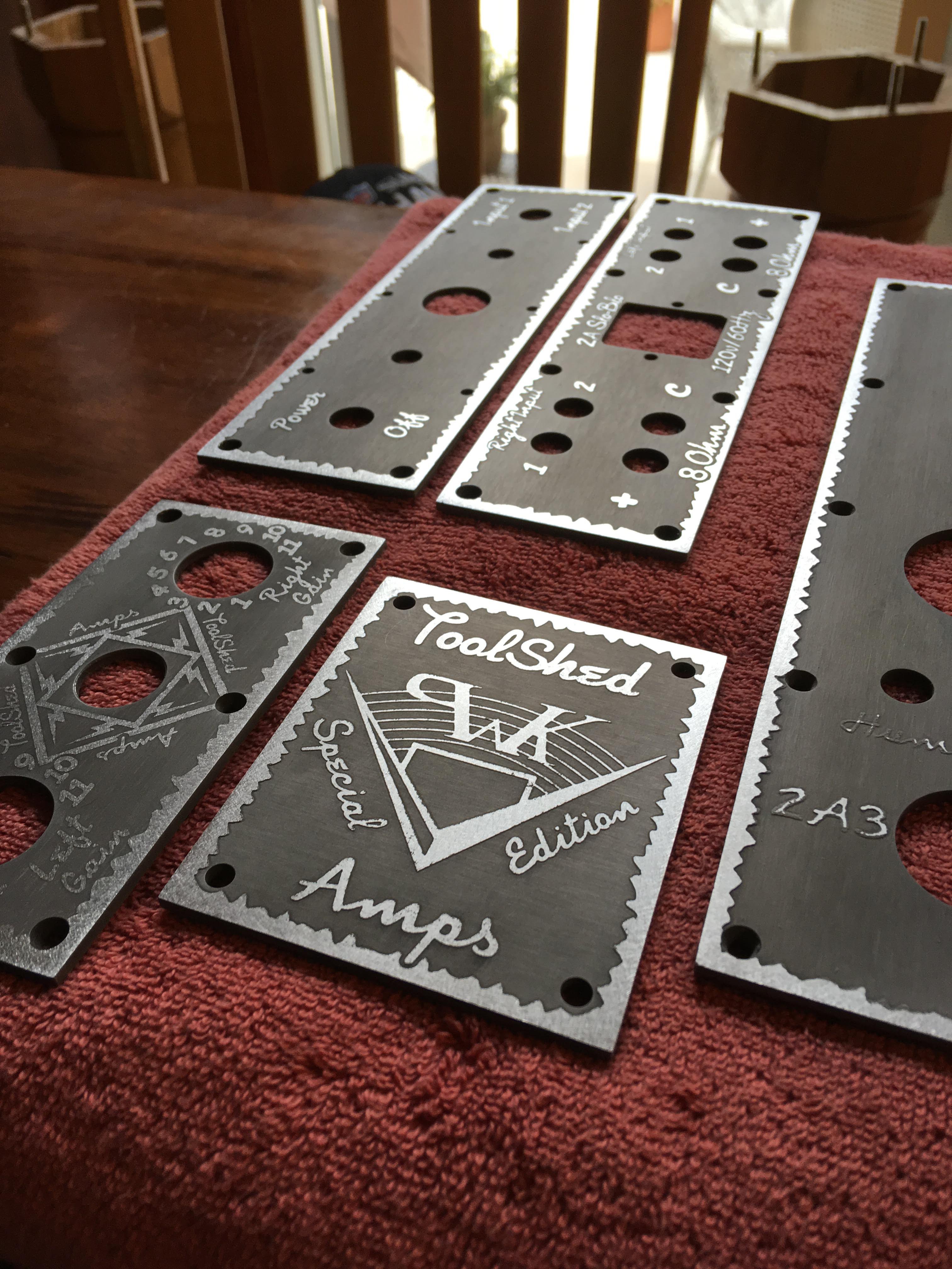
Ahh.... forgot to hit the "plus" buttons on the pics to add them to the post. After the plates are all etched, the backs will be sanded with the random orbit sander (150 grit) to clean them up and get them ready for polishing. The polishing step is probably the most labor intensive process for the construction of any of my amplifiers, it will be the subject of the next installment. Until then, here is a pic of the plates... pic of the plates after etching..... Cheers! Matt.
- 80 replies
-
- 4
-
-
- 2a3
- single-ended
- (and 1 more)
-
Henry Scott Yocum Memorial Amplifier Build
ToolShedAmps replied to ToolShedAmps's topic in Talkin' Tubes
Having difficulty uploading the pics..... hmm, they don't exceed the 2MB limit.
- 80 replies
-
- 4
-
-
- 2a3
- single-ended
- (and 1 more)
-
Henry Scott Yocum Memorial Amplifier Build
ToolShedAmps replied to ToolShedAmps's topic in Talkin' Tubes
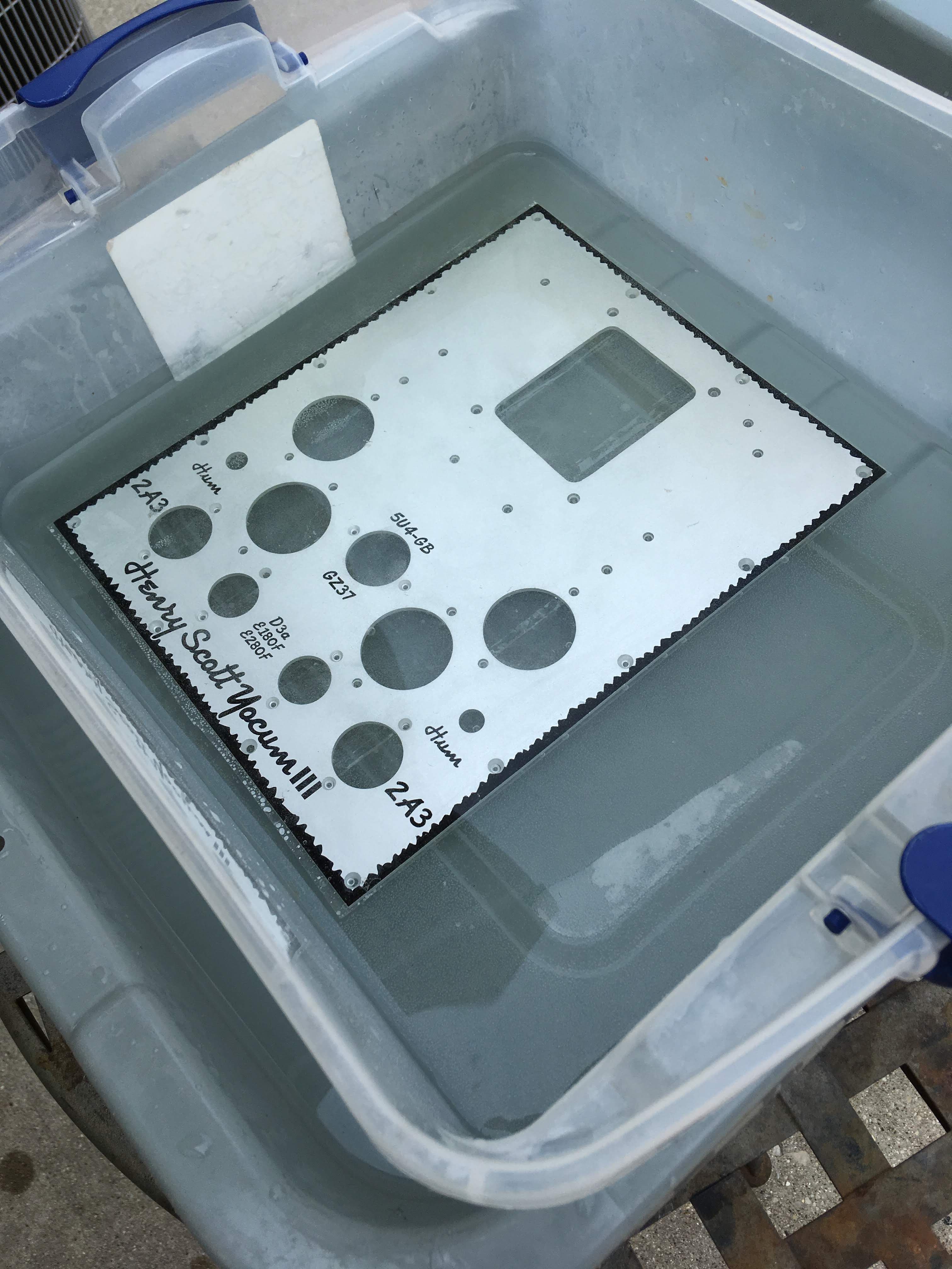
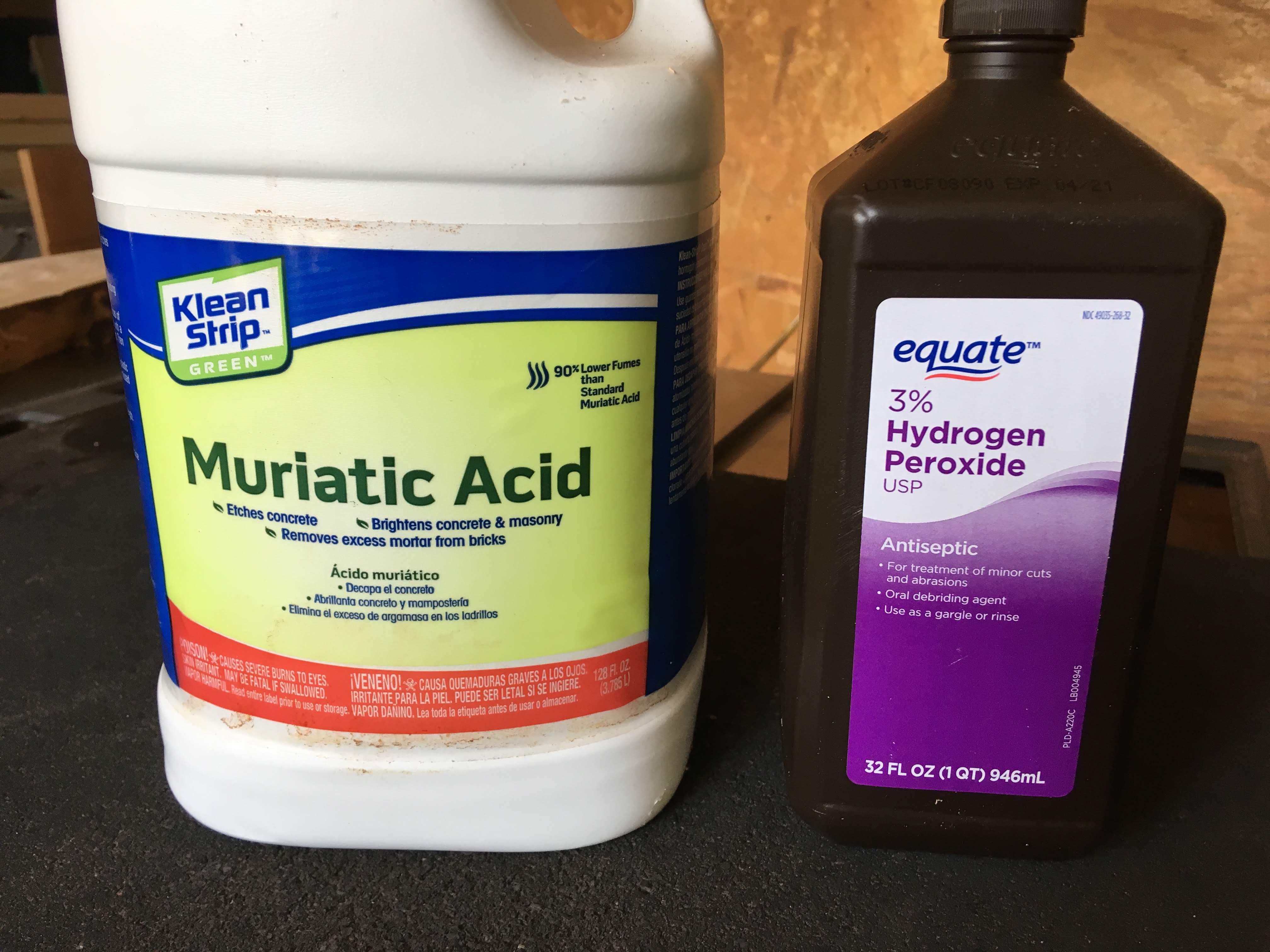
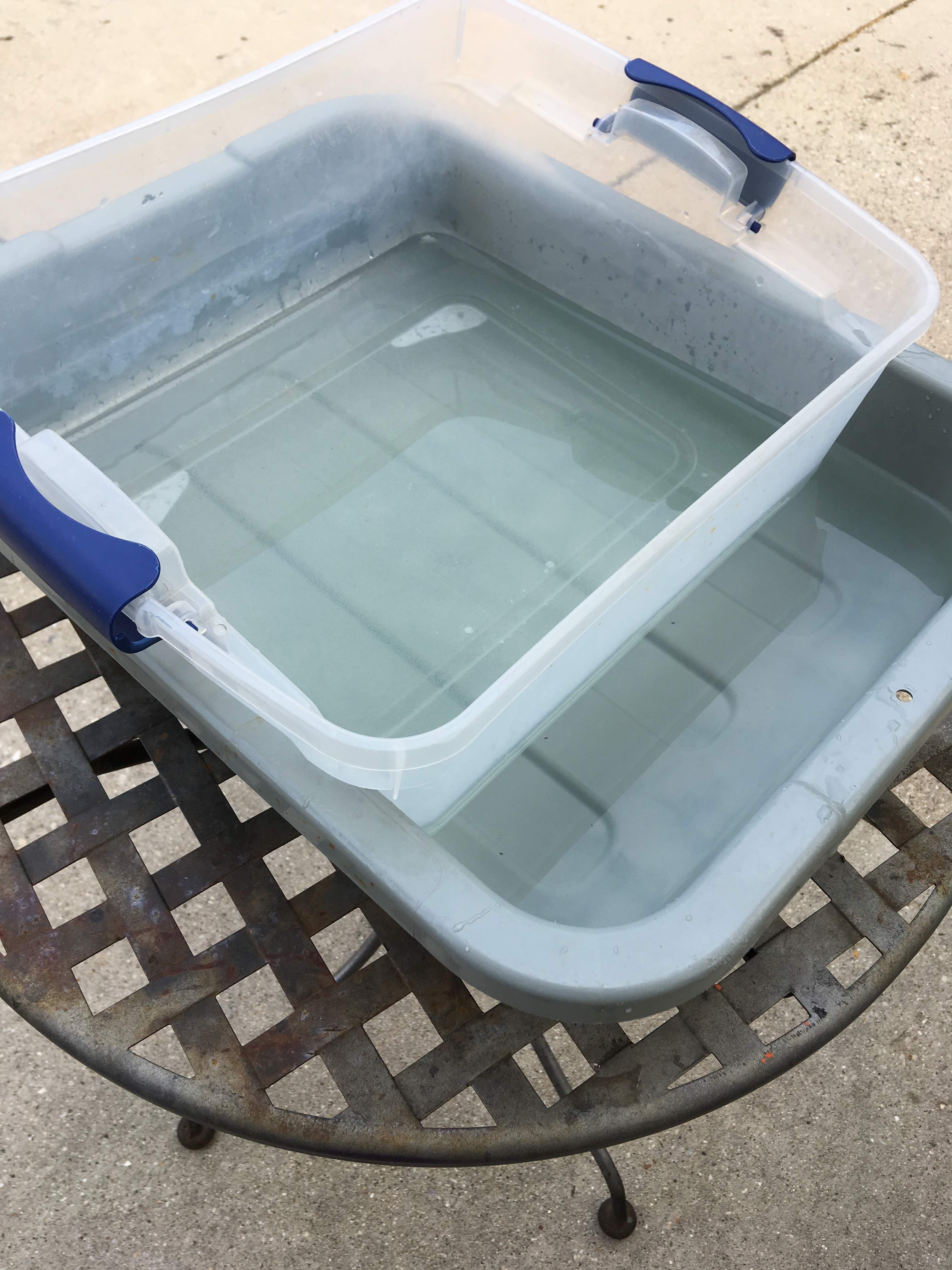
NOTE: The ratio of the chemical mixture is approximately 2:1, two parts Hydrogen Peroxide to one part Muriatic Acid. Measure and add the Hydrogen Peroxide to the bin 1st to avoid dangerous splash-backs. I use a stopwatch to time the immersion of the plates, it is highly critical and varies depending on ambient temperature and humidity. Good luck, it's taken years to get this sorted out, but, I think the results are worthwhile. The 1st pic was taken after dropping the plate into the solution...... the second pic was taken just 60 seconds later. The total time immersed was 210 seconds. The plate/s are then pulled out of the solution and dropped immediately into the lower tub of water and allowed to rest for about 5 minutes. The plate is then removed from the water and scrubbed with lacquer thinner to remove the baked enamel resist.- 80 replies
-
- 3
-
-
- 2a3
- single-ended
- (and 1 more)
-
Henry Scott Yocum Memorial Amplifier Build
ToolShedAmps replied to ToolShedAmps's topic in Talkin' Tubes
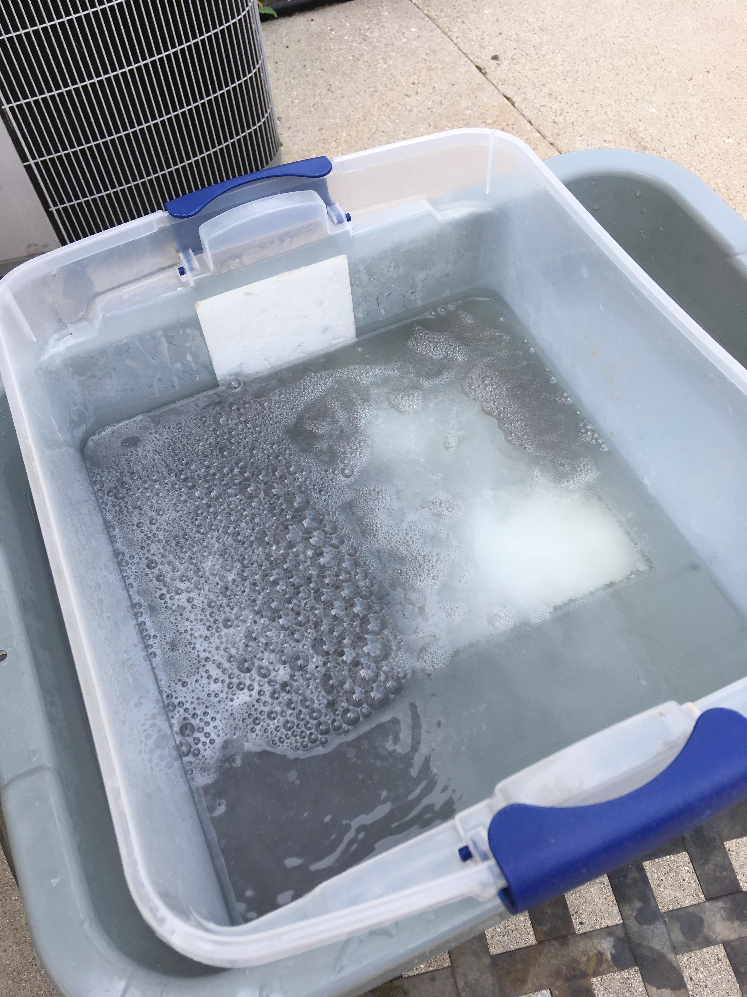
Howdy all, The method that I use for etching is a chemical process that can be considered a reductive acid bath. The two chemicals that I use are fairly benign in their unmixed state.... driveway cleaner (Home Depot) and an antiseptic cleanser (Walmart). However, when mixed and the Aluminum plate is added, this becomes a very violent combination and should only be done outside. Additionally, as the aluminum gases off I believe it is quite toxic as well, so take the appropriate precautions if attempting to do this. I finish prepping the plates by covering the back of them with packing tape to try to prevent as much erosion of these surfaces as possible (you'll have to re-sand them anyway to assure the proper contact of ground lugs). As this process generates quite a bit of heat, I "float" the bin containing the etchant (and plates) in a larger bin of nearly boiling water. See the pics.
- 80 replies
-
- 2
-
-
- 2a3
- single-ended
- (and 1 more)
-
Henry Scott Yocum Memorial Amplifier Build
ToolShedAmps replied to ToolShedAmps's topic in Talkin' Tubes
Excellent job William!!!! I'm glad I'm inspiring you to push out of your comfort zone and do better work, after all, you'll be looking at your amplifier every time you turn it on. Your finger joints look great. Take your time and block-sand the base from 100-120 all the way up to 380-400 grit. If you don't have an HVLP sprayer like I use, you can still get great results from spraying lacquer from a rattle-can if you sand between coats with 600 grit wet-or-dry paper wrapped around a piece of cork. I look forward to seeing your amp progress. Cheers!- 80 replies
-
- 2
-
-
- 2a3
- single-ended
- (and 1 more)
-
Henry Scott Yocum Memorial Amplifier Build
ToolShedAmps replied to ToolShedAmps's topic in Talkin' Tubes
Thanks Steve! FYI, I've decided to upgrade the amp from the standard N.O.S. Amphenol tube sockets to the new CMC Bakelite sockets so that the family can't possibly insert the power tubes the wrong way. This makes it just a little more user friendly. Cheers! Matt.- 80 replies
-
- 2
-
-
- 2a3
- single-ended
- (and 1 more)
-
Henry Scott Yocum Memorial Amplifier Build
ToolShedAmps replied to ToolShedAmps's topic in Talkin' Tubes
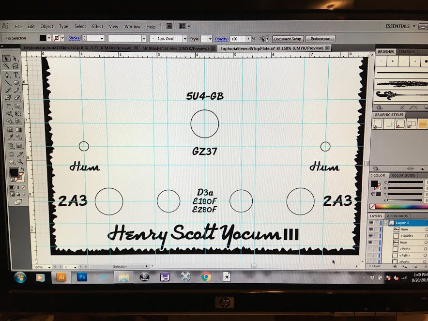
Just a glimpse of the computer screen showing Scott's top-plate.
- 80 replies
-
- 4
-
-
- 2a3
- single-ended
- (and 1 more)