CindyJarvis
-
Posts
64 -
Joined
-
Last visited
Recent Profile Visitors
1240 profile views


CindyJarvis's Achievements
Advanced Member (3/9)
28
Reputation
-
Pink Floyd's album finally scientifically explained
CindyJarvis replied to Rivervalleymgb's topic in Lounge
I thought sound can't propagate in space? It is a vacuum after all right? -Cindy -
Once again please don't include me in your witch hunt. And personally myself and most competent engineers usually lift the center tap to around 50vdc and not 2-3v. And here I don't mind educating you because it appears you need it. Elevating the heaters will reduce hum by reducing or saturating the leakage current between heater and cathode. You know nothing about me so don't begin to think you do. The laymen on here might be impressed with your bullying but anyone with a pinch of technical prowess can figure out you don't know bull. You act like a scared animal backed into a corner when presented with a technical question. But hey I get it, if you can't answer the question by all means attack the credibility of me but all it does is prove you know nothing and that you would be better off being a politician than an "amp tech". Everyday I am here you prove yourself more and more incompetent in my eyes. You can do two things, continue with this charade or just speak your mind and prove me wrong. Oh and I do read your other posts and I find it a bit sad you have to drum up business the way you do, it's actually pitiful. Someone needs more hugs in life or something -Cindy
-
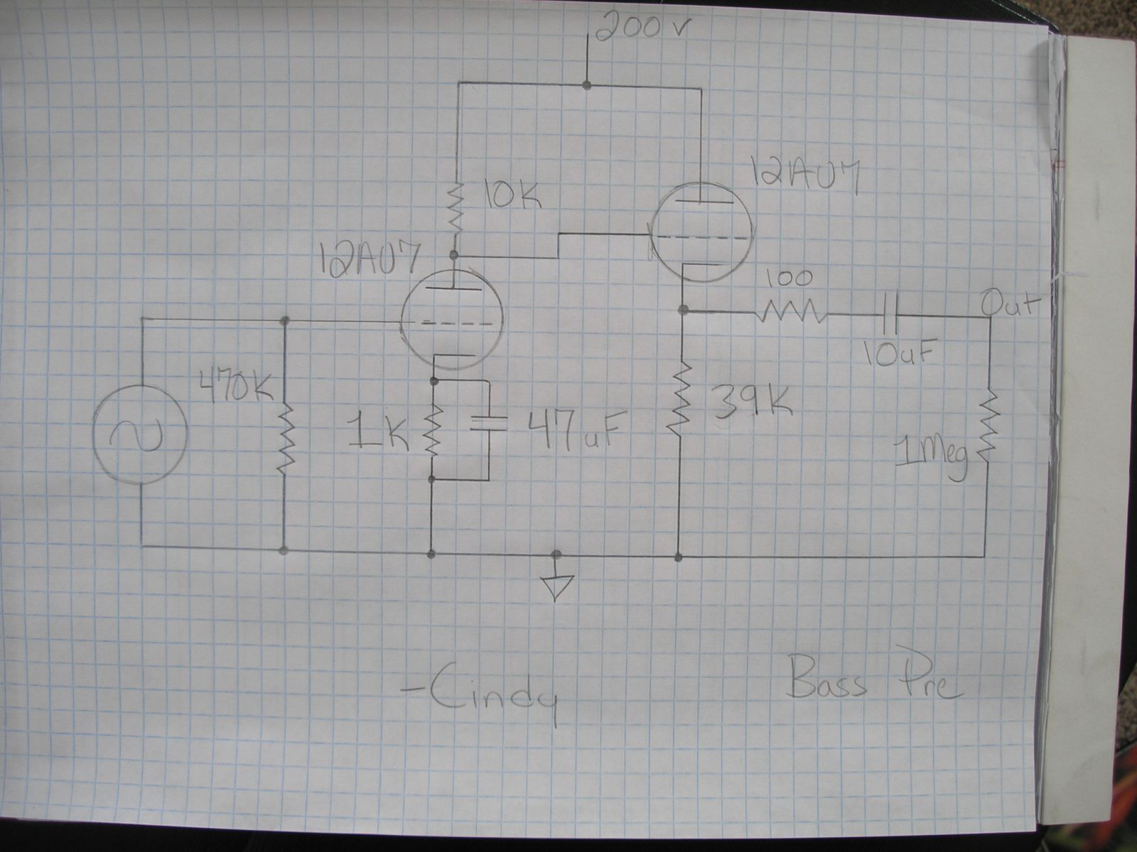
The caps can be what ever dielectric you want, Aluminum are the cheapest. The 47uF must be 10v or higher and the 10uF must be 250v or higher. As for the 10uF cap, if you want to go with a higher quality film cap you can lower the value depending on what you think it will be driving. Basically if it is being plugged into an amp I don't think it will see anything lower than 100k, this means you could use .33uF. 10uF was kind of a safe value so you wouldn't get any bass rolloff while driving heavy loads. The 1Meg is a load resistance which will be in parallel with whatever you plug in. -Cindy
-
I think I figured it out. I biased the follower so that it is really close to 0v so the two stages interact with one another. It should be rich in second order harmonic distortion. Gain is around 18db. You could always stick a volume pot at the input too but I assume your instrument has volume controls. What do you guys think? -Cindy
-
-
-
I drew something up for the tube builders to take a look at, problem is I can't figure out how to upload it to the forum. Anyone care to help me? -Cindy
-
I can draw something up if the tube guys haven't already. A couple more questions. Are your bass' pickups active or passive. Same question for the acoustic you plan on getting. -Cindy
-
Yes. You should still be able to drive a reasonably long cable like 10'-20', pick a higher transconductance tube and get a lower output impedance, plenty of current too, 5mA-10mA. How much gain do you want? How about adjustable gain? Tone controls? The world is your oyster. -Cindy
-
http://www.ampeg.com/pdf/svtdi.pdf Most guitar amps don't have a balanced input. Keyboard amps do I guess. The device is meant to drive a long cable from a stage to a soundboard. The block diagram does show what looks like a common cathode gain stage directly coupled to a cathode follower. The cathode follower will have a low output impedance and the output transformer lowers it even further and converts to balanced. Make note of the -14db gain. I find it strange because with all passive pickups there will be a resonant spike in the midrange, the placement is dependent upon the parallel capacitance of the cable and the inductance of the pickup. I think this is why most guitar amplifier tone stacks will scoop the mids to to flatten things out. Of course if you were sending the signal to a soundboard with a competent engineer he would adjust the sound accordingly. But most people that wouldn't know this or don't have the ability to flatten the mids might end up with a lumpy sound with boosted mids. Other than that I am sure someone here that builds amps could make you something very similar relatively easy. -Cindy
-
Yes. -Cindy
-
Hello, do you have them all plugged into the same electrical outlet? If not try doing that. It sounds like a ground loop passing through the interconnects. The reason the iphone doesn't do it is because it is battery powered. -Cindy
-
Any other people out there using chopsticks regularly? We use them in the house all the time, I think it's a fun way to eat. -Cindy
-
Are amps 'A' and 'B' the same? If yes running different rectifiers could yield audible differences depending on the topology of said amplifiers. If the amps are not the same it's like comparing apples to oranges. Depending on the topology of the amp you could hear a difference. Power tubes in a common cathode configuration with the output taken from the plate takes a small change in voltage at it's grid and creates a change in current at the plate, this change in current across the plate load (Rp) creates a larger voltage swing. All tubes manufactured slightly differ, even in the same production facility, these small differences can be audible due to the amplification nature of the device. A rectifier has zero amplification of signal, it's only job is to pass current in one direction and that's it. It does this by physics, the electrons boiled off the cathode can only flow in one direction, to the positively charged plate. -Cindy
-
Jim you bring up some good points to the "why's". Maybe if the countries ideals don't change for the better at least kids can start eating more healthy. -Cindy
-
Yes, it appears we have reached our saturation point. Let it grow! -Cindy