Doug
-
Posts
13 -
Joined
-
Last visited
Content Type
Forums
Events
Gallery
Everything posted by Doug
-
Would it make sense to simply calculate the current passing through the swamping resistor using Ohm's law when playing constant volume/frequency sine wave? Seems like it should be straightforward to determine what fraction of the total current delivered by the amp is being shunted to ground via the resistor, which would provide some good empirical evidence for the question on whether it makes a significant impact on the available headroom in a system. Edit: I guess this would make more sense using pink noise? Is this something I could do with my digital multimeter? Would it be valid to measure the voltage drop across the entire network (between the + and - input terminals) to calculate total current being drawn by the loudspeaker, or is this more complicated than my rudimentary understanding of electronics is leading me to believe?
-
I just broke my post-election-mourning facebook avoidance and happened to swing by Al K's facebook group. It looks pretty likely that he was in fact "Robonerd" based on his rant about this thread, which is kind of disappointing to me. I don't think anyone cares about how much current their audio equipment is drawing from the mains, as long as we like how our systems sound. Robonerd's argument seemed to be based on the assumption that people run low wattage SET amps to save money on their utility bills, which is completely absurd. My understanding is that people prefer the sound of these amps to more complex ones with more power, and that is why they run them and why limiting headroom with resistors in crossover networks MAY be an issue... I guess I was hoping the man behind the swamping resistor concept would have presented a more coherent argument, especially since I am inclined to believe that the swamping resistor is a good thing!
-
PM sent about some of the 6DJ8's!
-
This is super cool! Thanks for sharing! In one of AL K's unnecessarily abrasive rants on his website, he points out that the total efficiency of a Klipsch heritage speaker is determined by the woofer, not the squawker since the mids are always attenuated in some way to make up for higher efficiency of the squawker vs. the woofer. Since there is no attenuation in his universal network between the input and the woofer, it seems to make sense (at least in my physics 101 level of electronics understanding) that the swamping resistor shouldn't decrease the overall efficiency of the loudspeaker. Mike, since "default" setting on the ALK universal seems to be a one tap of additional attenuation on the autotransformer compared to the stock Klipsch networks, is it possible that you simply were listening to the vocal recordings at a higher overall volume with the universals since the mids (where most of the music would be) would be more attenuated with the universal than with the AK3 networks? Maybe one could simply choose a less attenuated tap on the autotransformer in the universal for this type of music?
-
This is a very compelling argument, especially when one starts really geeking out and gets tempted to go down the path of extreme slope passive networks. Being pretty new to this hobby, I'm not feeling drawn to that rabbit hole as of yet. I'm actually quite happy with the sound of my ST-70 and Klipschorns with ALK universals. I debated doing a Crites-facilitated re-cap of my AA's shortly after I got my speakers, but ended up going with the ALK's because of the ability to adjust the midrange and tweeter levels. I'm mostly interested in this stuff in an academic sense and am learning a lot right now! I think it is pretty clear that there are many ways to arrive and the subjective goal of good sound. Thanks for your patience and for sharing knowledge with a newb!
-
So, this results in fewer decibels of sound at the frequency where the impedance is high?
-
Sorry if my "sonic consequences" phrase came across as a value judgement. For the purposes of the question, I don't care whether networks sound "better" with or without the swamping resistor. I'm simply trying to understand what exactly the effect of uneven impedance across the frequency spectrum would be in terms of output from the speaker (in very basic terms). Sorry if the answer has been stated already in terms I just don't understand, but with a SET amp and a stock AA network (no swamping resistor) in a Klipschorn, would there be more or less output at the frequency where the impedance is the highest? In other words, would would a SET amp driving a stock AA network result in more or less midrange output from the loudspeaker compared to the same amp driving an equivalent network with constant impedance (assuming the same taps are used on the autotransformer)? Does 70 ohms equal more or less decibels from the loudspeaker at that frequency compared to a frequency where the impedance is 4 ohms? This seems like it would be testable with pink noise, a good mic(s), and some analysis software.
-
Looking back at the ALK webpage, I think it is pretty clear that he does build the Cornscala-wall networks to suit the customer: "The low frequency crossover is 1st order at roughly 400 or 600 Hz." I think this explains why the OP's network has the 33 uF cap (he has cornwalls). I wonder what the woofer inductor value is in the OP's network... I think I'm actually in a position to test this. My buddy has SET monoblocks and some unmolested AA networks in his Belles. When time allows I want to go over there and rig up a switch to compare the super AA to the stock AA and see if we can hear the difference.
-
Good find RoboNerd! From reading that thread, it sounds like choosing the capacitor value has more to do with cancelling out the value of the inductor + woofer voice coil inductance than it does with determining the precise crossover frequency: "In the Universal network, the entire filter is just a single inductor, so I just subtract the 1 mHy voice coil inductance from the 2.3 mHy inductance required for a 400 Hz crossover leaving 1.3 mHy. That's the value I use in the Universal network. This keeps the constant 6 Ohm resistive impedance when the 24+24 uF caps of the highpass channel cancel the inductance of the woofer filter plus the voice coil inductance." On a related note, it seems like constant impedance is a big feature of ALK crossovers. What are the sonic consequences of non-constant impedance? I've read Al's website, and he says something like "amps don't like it when impedance varies with frequency", but I'm wondering what this really means. Will it make your amp wear out sooner? Does it cause attenuation or distortion of the frequencies where impedance is higher? Lets assume we are running a "worst case scenario" low wattage SET amp for the purpose of discussion.
-
I think it is possible that Al varies the value of that capacitor in the super AA's he rebuilds based on the speaker they will be going in to. The ones I put together were completely DIY, based on the schematic from the ALK website, which might not be the only way he does them (purely speculating here). On the other hand, from what I have read on the ALK website, Al doesn't seem to be the kind of guy that readily accepts alternatives to the values he calculates for these sorts of things, and it seems like based on his math, the values of capacitors and inductors need to have very specific relationships to each other... Also, doesn't the stock AA found in the Klipschorn have a 13 µF cap in this position? I'm way out of my depth here, but wouldn't that make the crossover frequency even higher between the woofer and squawker than either of the cap values we are talking about here in ALK networks?
-
Thanks Dean! I've been lurking around for a while and thought I could provide some useful info on this
-
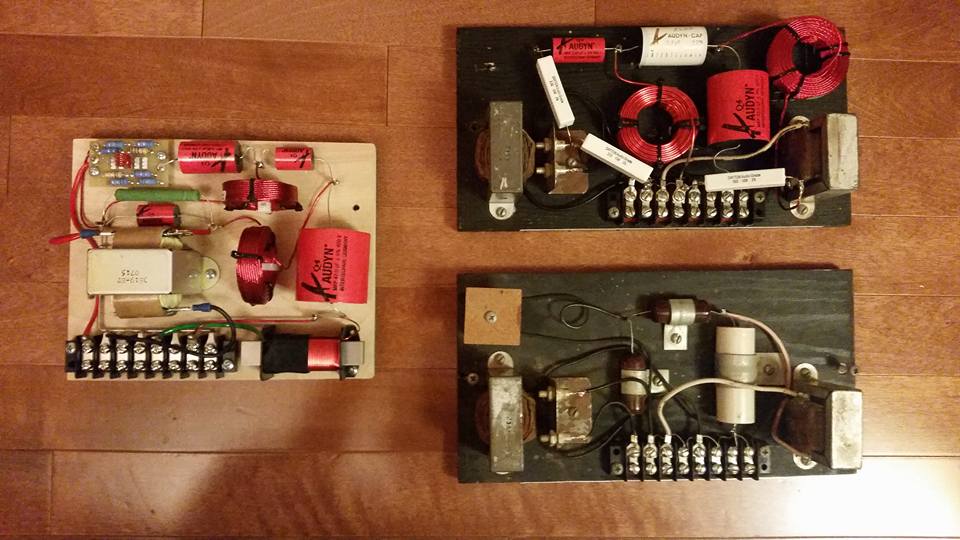
I received my Cornscala-Wall Universals from ALK a few months ago and the large capacitors in mine are 47 µF. I remember talking to Al about my speakers (Klipschorns) when ordering them, so maybe he is choosing different values to suit different speakers after all? Also, I just finished up converting my original AA's to "super AA's" according to the schematic on Al's website. These have a 33 µF capacitor. I did a quick test with a universal in one Klipschorn and a "super AA" in the other, and then switched between channels while listening to the same song. Both networks sounded VERY similar. I may have perceived slightly more bass from the universal, but this could easily have been due to differences in the room (my corners are not identical). To do this correctly, I wish I had a switch that could allow both networks to be hooked up to the same klipschorn. The $99 super AA upgrade that Al is offering is quite a bargain by the way. I think I actually spent more than that on parts for my DIY project (equivalent parts used), and the solder joints and wire routing on my universals from Al are definitely prettier than what I was able to cobble together.