Maz4bz
-
Posts
102 -
Joined
-
Last visited
Content Type
Forums
Events
Gallery
Everything posted by Maz4bz
-
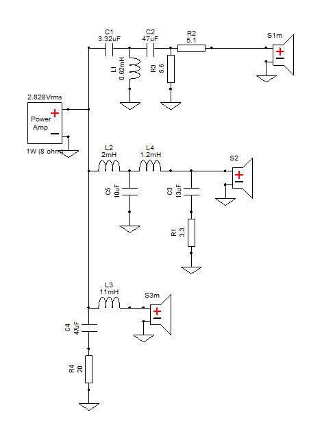
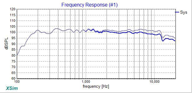
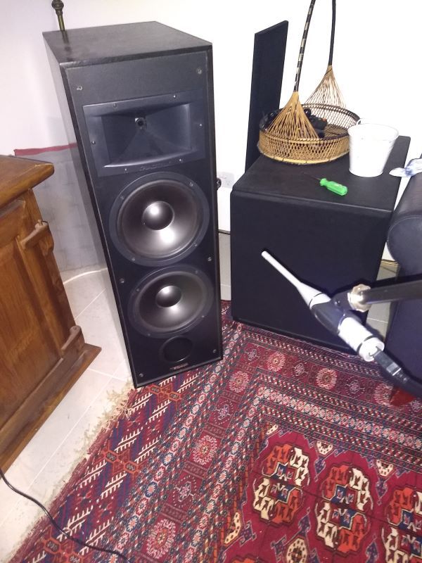
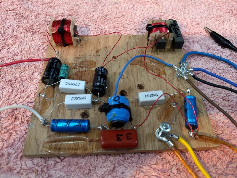
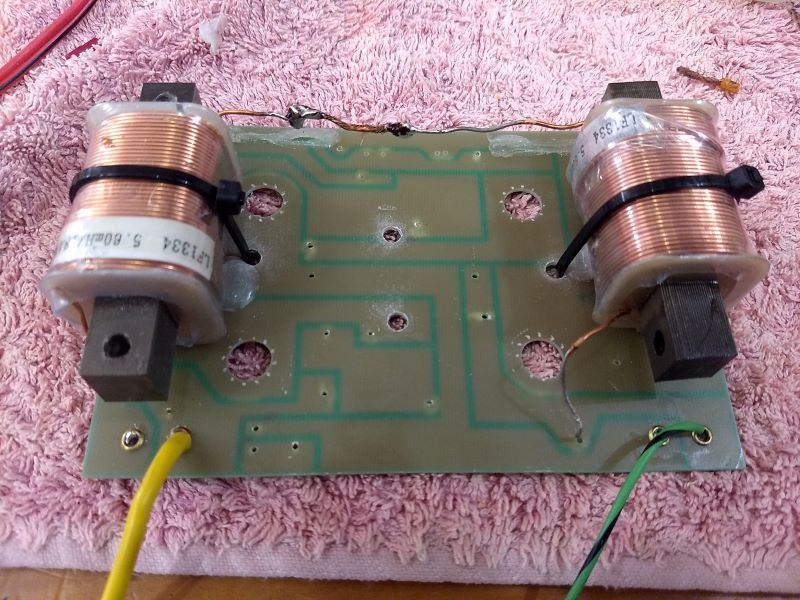
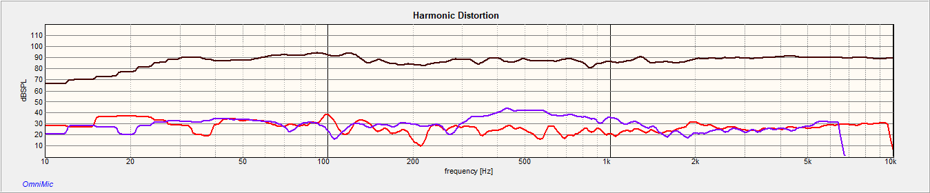
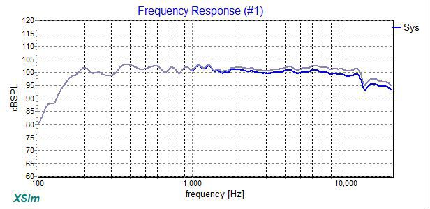
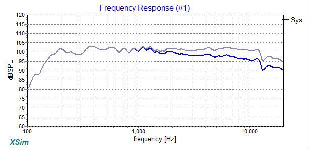
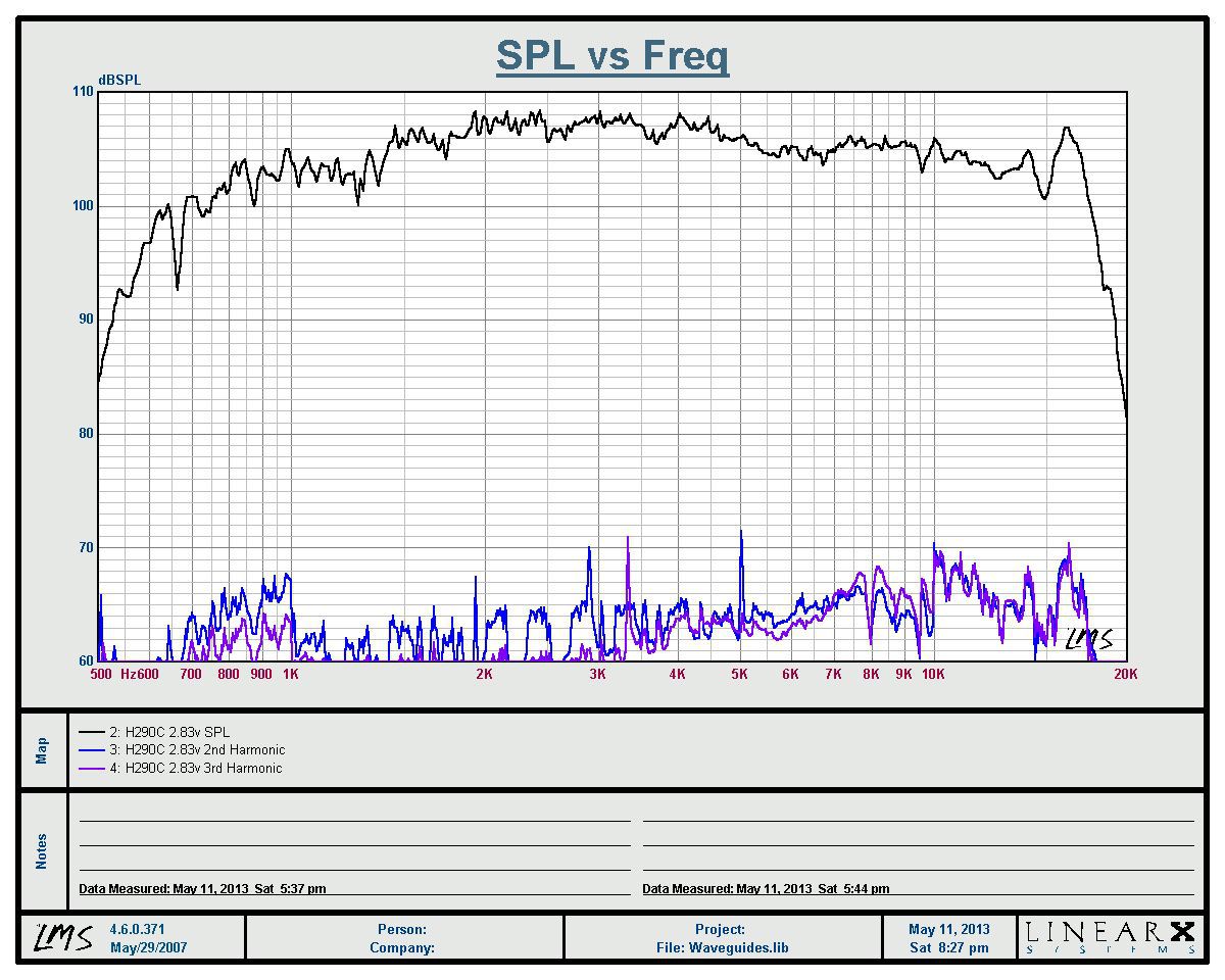
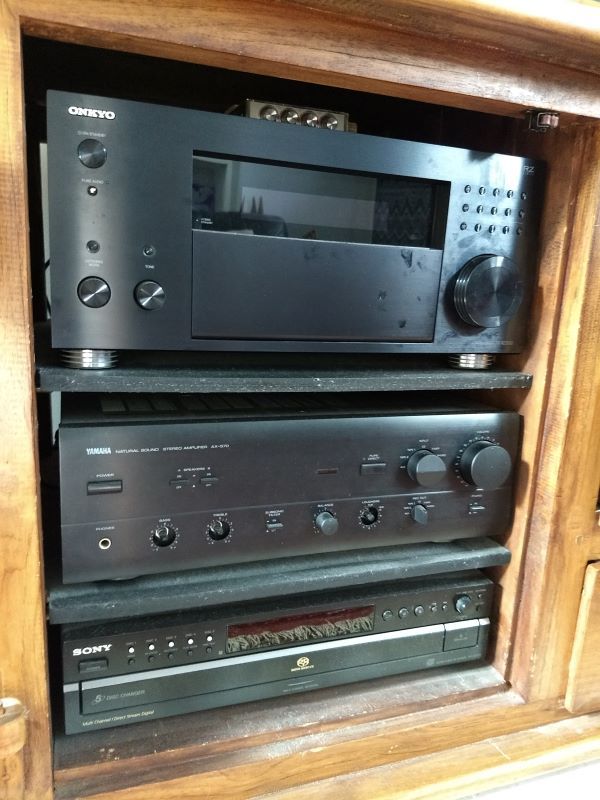
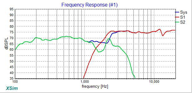
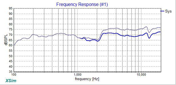
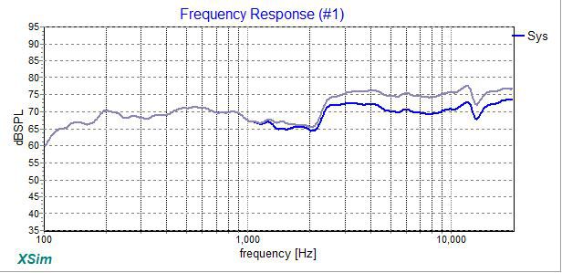
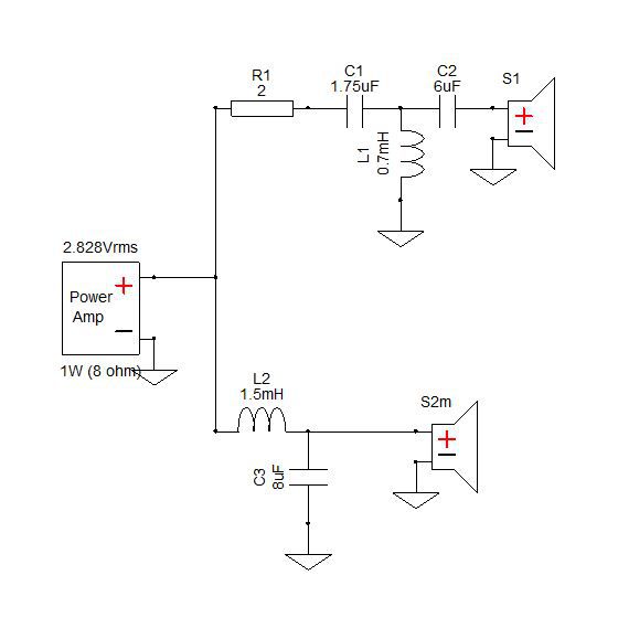
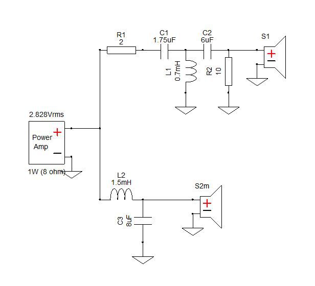
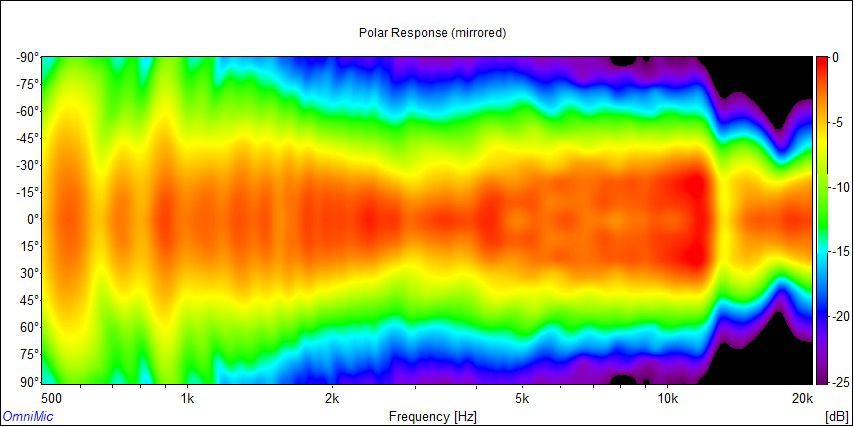
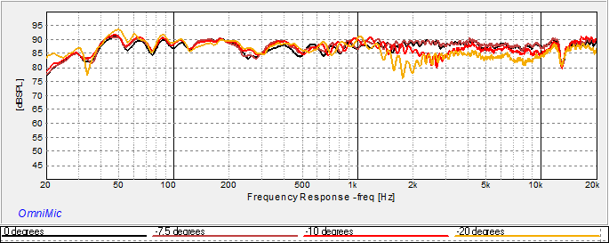
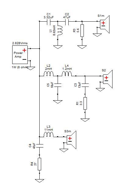
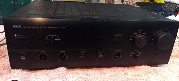
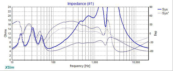
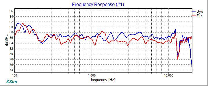
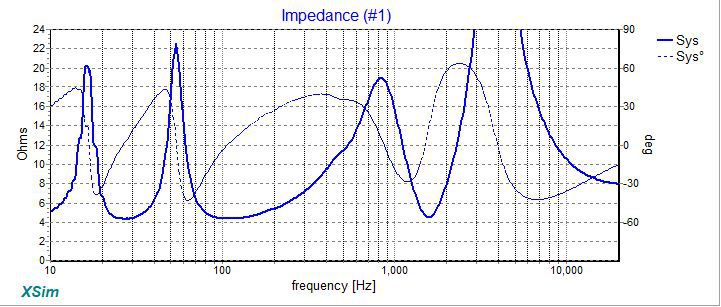
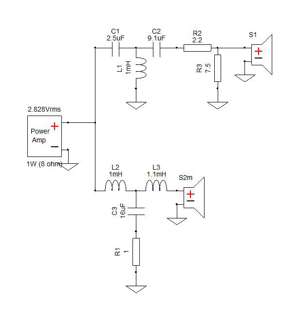
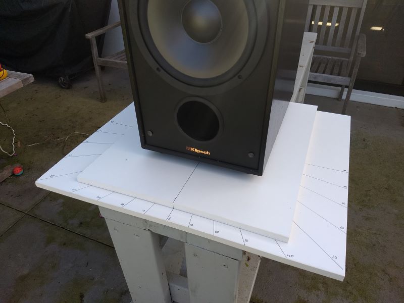
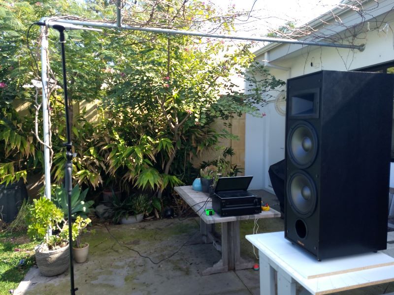
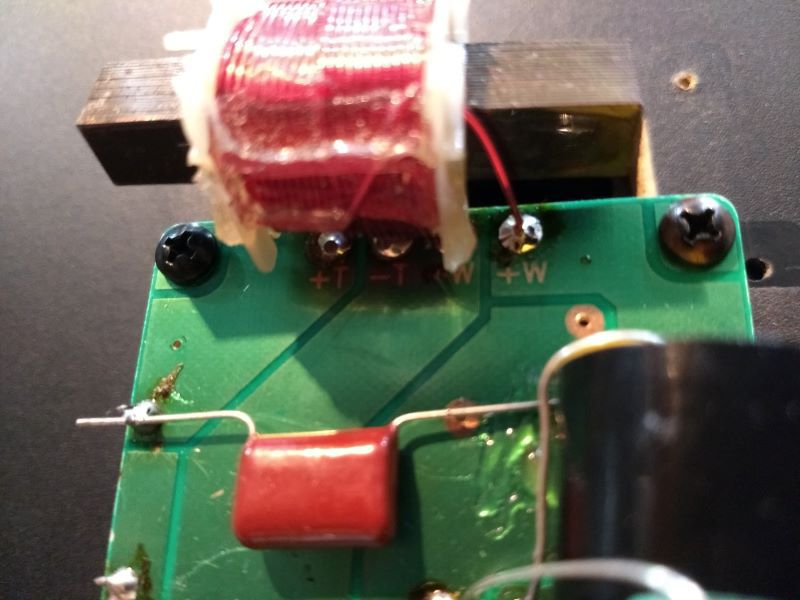
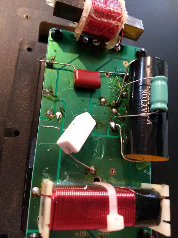
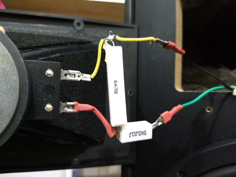
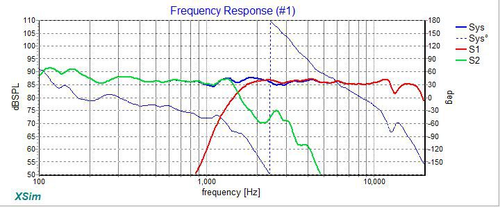
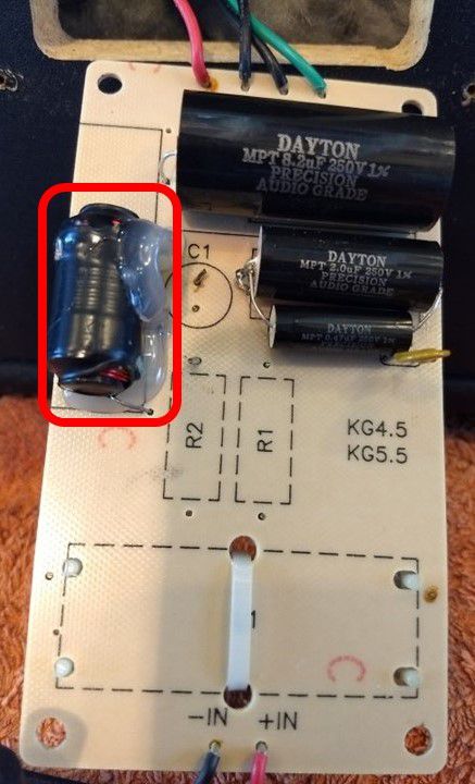
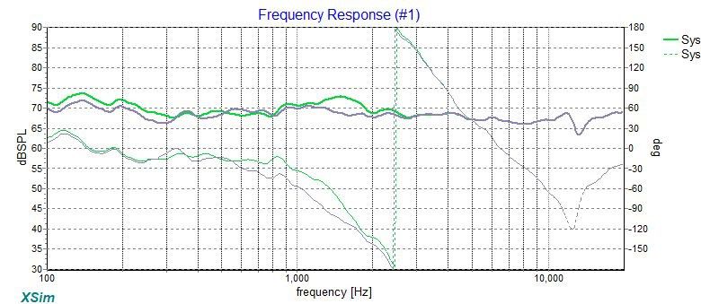
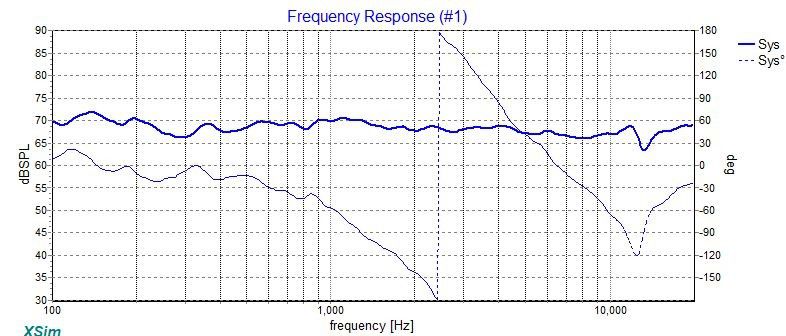
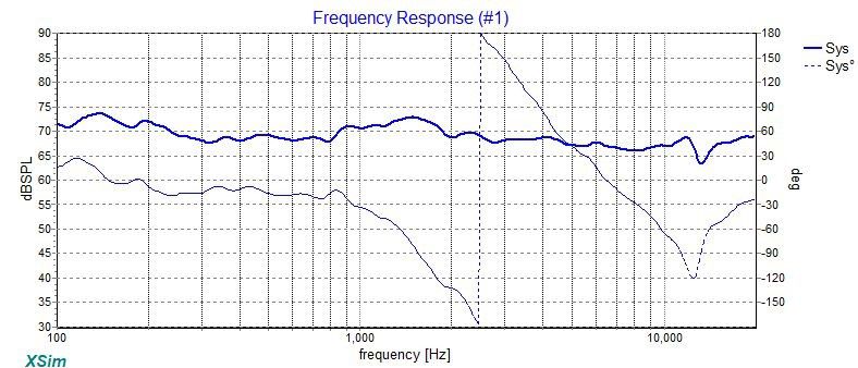
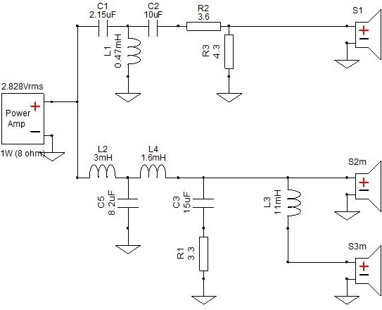
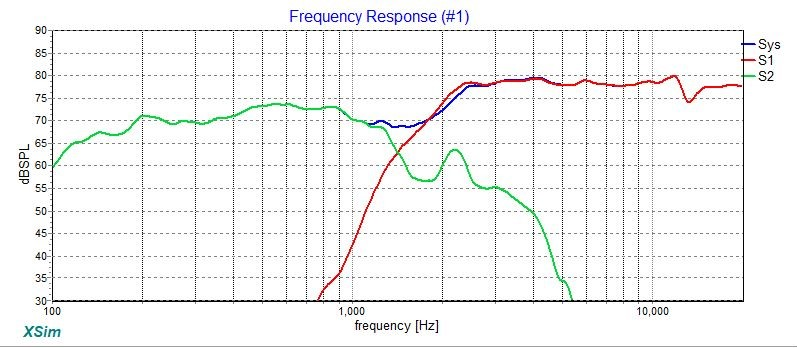
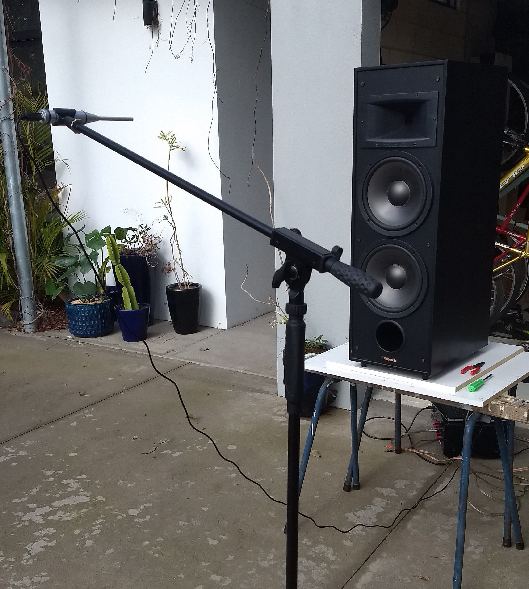
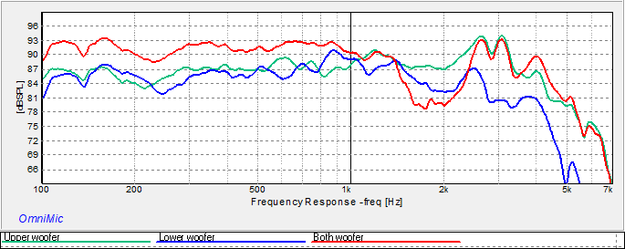
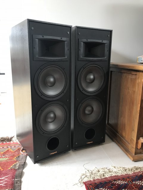
Dear all, Stage 2 crossover upgrade V0.23: Tweaking the 2.5-way design with measurements. So I have built up my second 2.5 way crossover. I made a few minor changes to the layout this time: added back a series resistor to shape the tweeter response a little; I kept the impedance smoothing section made up of C4 and R4 on the main board; added a positive binding post; and relented and unwound a second 3.5 mH inductor to make up my missing 2mH. Here's the tweeter and upper woofer board.... For my 0.5 section or lower woofer board I tried using one of the deconstructed crossover PCB's that I now have many of after harvesting all my LCR parts. This worked out great and simplified the wiring to the lower woofer which now takes a negative lead from the main board negative binding post. I have used two 5.6mH inductors in series to get my 6db roll off for the lower KG woofer.... So the KG pair are installed back into my main listening room and I've had a few weeks to enjoy them and I am happy to report that they do indeed sound AMAZING! The first listening impression I got was a sense of a big step up in the clarity of the midrange. Vocals really shine through where before these seemed more recessed. With this clarity comes a deeper level of richness in many kinds of music that I don't think was there previously. I really wish I had another pair that I could A/B with, original crossovers to new 2.5ways, but I don't so I'm relying on memory, and all of that sense's frailty. After some time I began to realise just how revealing of the recording quality this design is, and after a while I began to think I wanted to round off the treble just a smidge because I really do like just a bit of warmth, which I think makes medium to loud listening more enjoyable. So I went back to XSim and came up with a very minor tweak I'm calling my 2.5way V0.23. This adds a single series resistor R2 to the tweeter (S1m) circuit. I modelled and installed a 5 ohms unit.... This additional resistor has the effect of just slightly tilting the top end downward, softening the very high frequency treble.... R2 is highly tunable, here is the effect of R2 @ 10 ohms..... Here is R2 @ 3.3 ohms.... Feel free to tune R2 to taste, there is no right or wrong here, as Troels Gravesen says: "Some call the voicing of speakers an art. I don't think so. Voicing a speaker is a matter of taste like adding spices to a stew. Some like it hot, creamy or crunchy - some don't." For completeness I wanted to show some measurements. These were all done in my lounge this time. The only change to the position of my speakers where I normally have them when listening is that I moved the right hand speaker out into the room a little so that the front driver baffle just clears my nice cabinet and DIY 15" Alpine sub. Despite being far from an ideal measuring environment I think the results are great. Biased? Yes, probably! At least the data allows for some objectivity. Here's how I measured.... I didn't carefully measure 1 meter away from the cabinet front this time. I just set the mic height by putting it right up to the centre of the tweeter and then pulled the mic stand back roughly 1m and measured..... Results - +/- 2db Here's the left and right comparison, pretty well dead on match for frequency response. I level matched these by knocking 2db off the right enclosure. The right speaker measured a bit louder due in part to the imprecise distance I measured each speaker from and because the left speaker is placed out in what is almost 2 Pi (free standing) space adjacent to the intersection of my lounge/kitchen/dining room compared to the right enclosure being in 0.5 Pi (corner) loading.... Zooming in I think that we might safely call this a 2db +/- result? That sharp dip between 800 and 900 hz is room related, it isn't a feature in any of my outdoor measurements .... Distortion measurement - a comparison Wayne Parham at Pi Speakers has published various system and horn/driver combo frequency measurements that make for an interesting comparison. His Pi H290C waveguide with a B&C DE250 have measured distortion just over 30db down..... Black = measured frequency response (also known as the fundamental). Blue= 2nd harmonic; Pink = 3rd harmonic. For comparison here is the distortion sweep of the KG's. Note that the output level was running at 90db which is quite loud and indicative of where I'd listen when the family are out. Black = measured frequency response. Red = 2nd harmonic; Purple = 3rd harmonic. I'm prepared to say the KG's are a very clean, low distortion system with the fundamental better than 40db above measured distortion. Way to go Klipsch! This graph also shows the KG's are solid down to 30hz measured like this. Based on this data I'd like to venture to anyone that says the KG's are just speakers for teenagers and rockers should rethink everything they thought they knew about them. I believe this shows conclusively the 5.5's can be extremely fine speakers, by any measure. So, I'm going to keep listening some more with this crossover design in place, I'm really enjoying it and feel that for me, the 5 ohms R2 on the tweeter hits a smooth, rich, balanced listen. Hooked up to my new, secondhand, cleaned up AX-570 (which just quietly kills my brand new Onkyo TX-RZ3100 (Pioneer SC-LX901 in a different skin!) hooked up to my KG's in my room) the bass is super articulate and authoritative. Midrange so clean and clear, treble sweeeeeet mmmmm! At least to me, of course! I think we have a winner here. The KG's continue to reward. The journey continues! Cheers.

- 58 replies
-
- 2
-

-

-
- cabinet bracing
- crossover refresh
- (and 4 more)
-
I should have added the XSim .dxo file I used to do the sims so you can have a play for yourself. Just head over to the XSim thread at diyaudio.com and grab the latest version from there. Please do let us know how you get on. If you need any help just sing out! KLF10.dxo
-
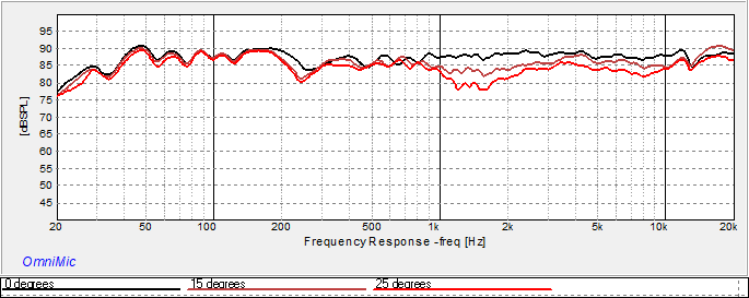
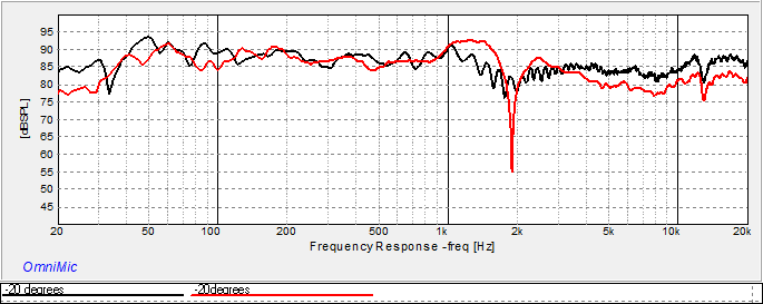
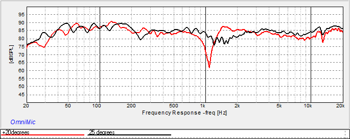
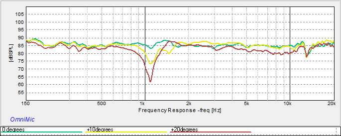
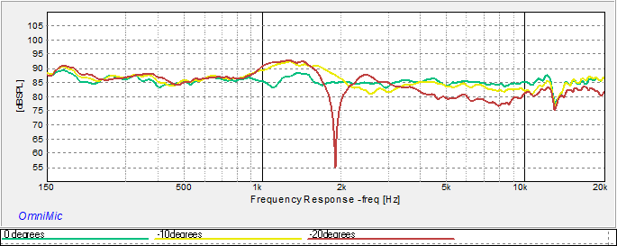
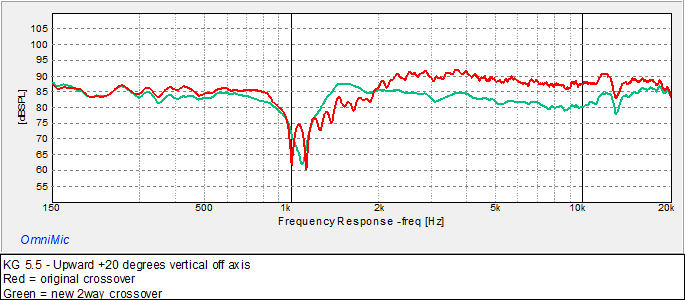
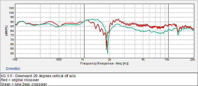
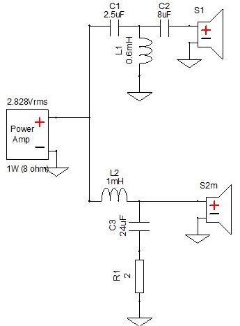
Nice stands. They turned out really great. You have some wood working skills for sure. I would imagine that your KLF10 sound wonderful as I adore my KG5.5's which are the KLF10's predecessor if I'm not mistaken, they do look similar with their dual 10" woofers and tweeter. As I sit in my lounge with my ears at tweeter height I've not lifted mine. I think you may have found that the double woofer, two way arrangement of these speakers has a very narrow vertical forward lobe, like I have. This means that when I move above or below the tweeter much, the midrange suffers. When I measure the KG's in two way configuration vs an all new 2.5 way crossover I've designed for this system there is a big difference in their off axis performance around the crossover region. Measured upwards 25 degrees above for 2.5 way (black) vs 20 degrees above for the 2 way crossover (red) .... Here is the downward measurement both at 20 degrees (again black = 2.5 way, red = 2 way)…. So I think you hit the nail on the head when you say your speakers bloom when you're on axis with the tweeter. This is also why I think our speakers deserve a 2.5 way crossover, rather than the 2way that they have. I thought I'd plug the KLF10 crossover that Moray posted a while back into XSim and load it up using the individual KG 5.5 driver frequency response measurements to see where your crossover is. I'd call this a 1500hz crossover where (green) both woofers wired in parallel and (red) tweeter frequency responses cross over: Now this is a bit academic as we are not using the individual measured frequency response of your KLF10 drivers here, but no matter, it'll likely be close but certainly not perfect! The KLF 10 crossover schematic is almost identical to the KG 5.5. The KLF woofers are a different model number, however the tweeter seems to use the same diaphragm. Notwithstanding if your drivers have similar sensitivity to the KG's then your tweeter will be around 5db or so hot like it is in the graph above. If this is the case then your KLF's can be sooooo much better! So I notice you mention the tweeter is a bit hot, same for the KG 5.5's. Here is a little suggestion I've modelled for you. Similar to what I did on my KG journey. Here is the original KLF10 crossover: I would like to propose a single change to the tweeter (S1) circuit with the addition of a resistor R2 of 10 ohms: This will result in the following change in output to the tweeter, grey is original and blue is new: This flattens the tweeter to be more in balance with the woofers and should be a BIG improvement. It was for the KG's. Of course we are not working with the measured response of your KLF10 drivers so you can adjust R2 to taste, there is no right or wrong here, as Troels Gravesen says: "Some call the voicing of speakers an art. I don't think so. Voicing a speaker is a matter of taste like adding spices to a stew. Some like it hot, creamy or crunchy - some don't." So here is the same crossover with a 6.2 ohms R2 for a more subdued top end: Or here with a 13 ohms R2 if either of the above took out too much sparkle: What I am proposing here is to experiment with the value of R2 until you enjoy what you hear. Resistors are really cheap. Buy a handful and have some fun experimenting. This change is completely reversible if you don't like it. It will take some time to acclimate to the changes, give it time and if you start to think too dull or too bright, tweak R2 some more. It took me some weeks of listening to adjust to the Lpads that I originally added to the KG's. I incrementally changed these until my speakers got too dark/dull. Then I retreated a little to regain some top end sparkle. What I settled on ended up being just about ruler flat with no measuring equipment. Trust your ears! If you are the scientific kind however, then a cheap USB mic and some free software is like being able to see for the first time. I highly recommend the investment. Wish I'd done it earlier. I use the Dayton Audio Omnimic system, it is a terrific tool and so easy to use. And don't worry about how low you can go in terms of ohms with R2. As an example if you set R2 to just 1 ohms, which I really doubt you'd ever do as it cuts about 15db output from the tweeter and would sound very dark, the system impedance never dips below 4 ohms. Here is the original crossover in grey compared to R2 @ 1 ohms in blue: Hope this helps and may your terrific Klipsch provide you many years of enjoyment - they are undoubtedly very fine speakers. Cheers
-
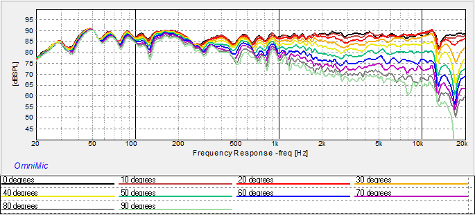
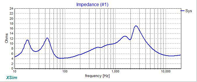
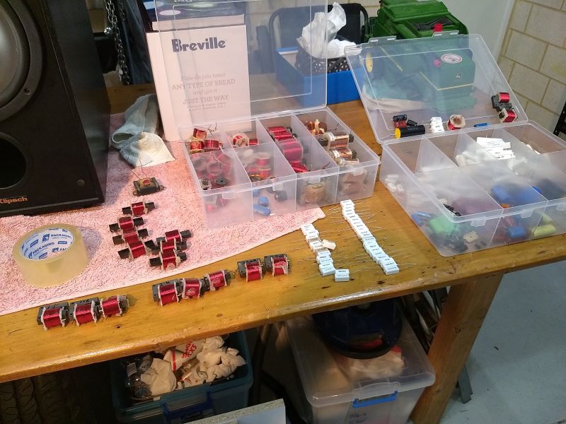
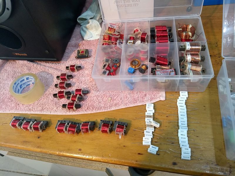
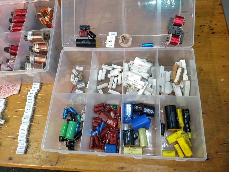
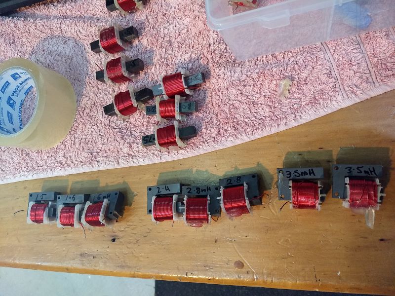
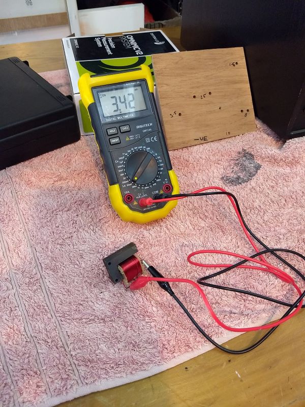
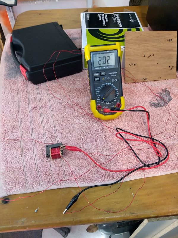
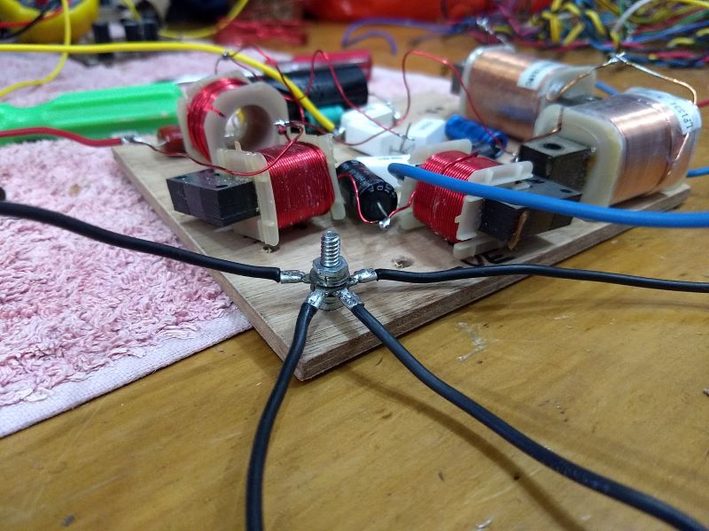
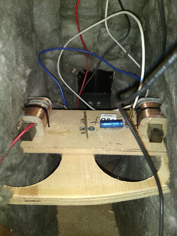
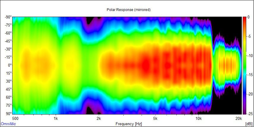
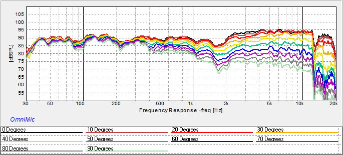
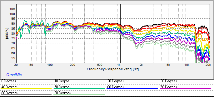
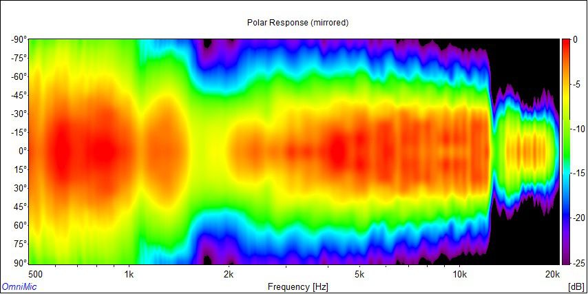
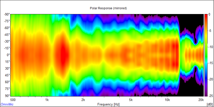
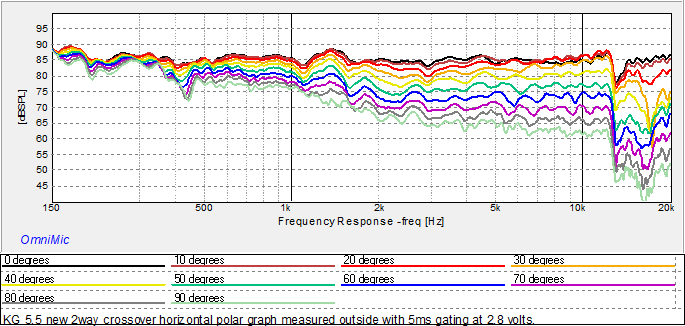
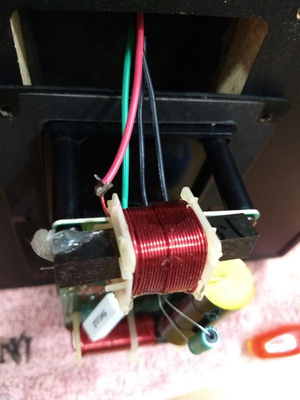
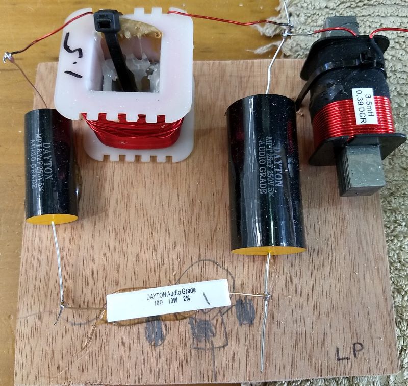
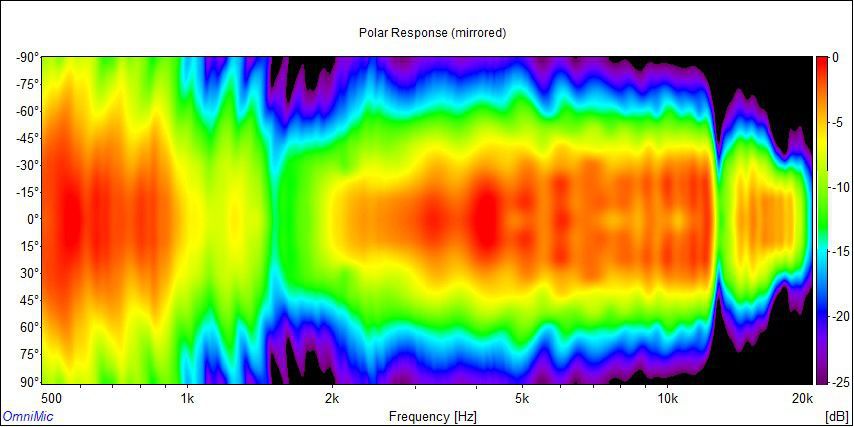
Dear all, Another update on my KG journey. Stage 2 crossover upgrade: V0.22 2.5-way design, build and measurements. So getting to a workable 2.5way design has been a bit of a process. Measuring speakers is definitely a skill, with the results affected by a lot of variables. To get to this point I have measured each of the KG's individual drivers on no less than seven occasions, each with a little variation to try to ensure I was going to land on a reliable result. My big learning here has been that being able to set the relative acoustic offset of the drivers is key to getting the forward lobe pointed in the direction that I actually listen. My first attempt at the 2.5way crossover resulted in a downward tilted lobe which would be a great design if you like to sit on the floor when listening! 😉 The version presented here however does indeed present a forward lobe that is directly in front of the tweeter horn which is the level my ears are at when seated on my lounge. Here is the new 2.5way V0.22 crossover schematic: One thing to note here is that I dropped the series resistor on the tweeter circuit, it wasn't necessary. Now you can very easily vary the tweeter output by adjusting the R3. I recommend only going up in value here if you'd like some added sparkle on top. Going lower will put the impedance above 10khz below 4ohms which may be a challenge for some amps or receivers. Here's the predicted response: And predicted impedance: I also wanted to show how I go about building a crossover, as I'm prototyping and most definitely not a professional, I'm trying to keep costs down. A while back I was lucky to snag a big box of brand new-old stock Energy Connoisseur and assorted other crossovers and terminal plates for a bargain on eBay from a local repairer. I deconstructed these for their LCR parts and ended up with a nice variety of components to enable me to start building up my XSim designs..... Separating out my parts... For this crossover I didn't have a 2mH inductor on hand so I had to unwind one of my larger value units. I chose a 3.4mH as I had 3 units of this value on hand and I'm aiming to have a pair of each value to enable me to build up prototypes for pairs of speakers so that I can listen to the results of each design in my lounge room. An essential tool for anyone keen on crossovers is a multimeter with measurement for capacitance and inductance. Here measuring the inductor to be unwound.... And now measuring the unwound inductance. I keep the excess wire as it's insulated and great to use as jumper wire between components on the crossover, I just burn off the insulation with my soldering iron by melting some solder onto the end of the wire... Some pics of the design build up, we're not fancy but we are cheap! 😁 Spread out here to keep the inductors away from each other, those cross braces added before are great landing pads for the new crossovers.... A little bolt is great for tying in all the negative side of the circuit. This is an image of the first version of my 2.5way design (with inductors too close together) .... The 0.5 section for the lower woofer installed in the enclosure, trying to keep those two big inductors away from each other... Horizontal Measurements All measurements are outside off the ground, the KG measured at 1 meter with 5ms gating, on axis and all the way around to 90 degrees off-axis, in 10 degree increments horizontal, no smoothing.... Dr Geddes style polar plot of the same data. Controlled directivity! This is our best result yet and brings a big smile to my dial.... Now for verticals. Upwards.... Downwards.... The moment of truth - would we bother with a 2.5way design when the original was a simpler/lower cost 2way? Let's allow the data to answer that question. Upwards - 2.5way (black) @ 25 degrees compared to 2way (red) @ 20 degrees …. Downwards 20 degrees - 2.5way (black) compared to 2way (red)…. That ought to be enough to answer the 2.5way vs 2way question. Whichever way you go, both will be a big improvement. The 2.5way will just sound better (I believe) in a wider range of settings, like when I'm standing up to iron my work shirts! It will also mean that the "sound power" or totality of direct and reflected sounds will be flatter. Dr Floyd O'Toole of Harman (JBL) investigates this in detail and concludes that this is the defining element of what trained listeners find most appealing in double blind tests. I've linked his paper here to this post as it is the basis for my efforts at finding the flattest response both on and off axis for the lovely KG's. This off axis performance data also kind of begs the question as to why did Klipsch choose the 2way knowing (I assume) the performance implications this would have? I suspect that this may have been a marketing decision to go with the higher SPL of the original crossover as a way to stand out on a crowded HIFI shop floor full of speakers from the opposition where first impressions count for everything. If I'm correct in this assumption then I understand their reasoning - we all want Klipsch to succeed! As I understand the psycho-acoustics we are drawn to the loudest sounds, initially. Perhaps we all appreciate the efficiency at first and then acclimate to thinking "these could/should be better" whatever that means to each of us, with our own unique tastes? So how does she sound? Notwithstanding a healthy dose of confirmation bias - AWESOME! Yamaha AX-570 my new amp! I've only built up one crossover (I'm still short another 2mH coil!) but last night I hooked her up to my new purchase, a lovely Yamaha AX-570, the bigger brother of my beloved AX-450. As lady luck would have it this old workhorse popped up on our local Gumtree for sale over the last weekend in less than stellar condition. She's missing a few knobs and her pre-main jumper bars. There were quite a few kids scampering around the house I picked her up from. She didn't emerge from that place unscathed! I negotiated the price to $30 and got her home for a test run. So everything works great, a pair of uber short RCA leads plugged into the pre-main sockets and all functions are online. My Harmony remote operates all the remote functions too! More HIFI happiness! With a real 100 watts under the bonnet of the AX-570 I connected up my android phone to the CD input, engage Pure Direct and let rip on the upgraded KG with some FLAC encoded RUFUS Solace which has some THUNDERING bass. And oh my, the KG's soaked it up and put out some super smooth sounds. We definitely lose some SPL with the 2.5way design compared to the 2way by taking out the lower woofers output early. That's the point after all. But we lose nothing in the bass department. Relatively we might say we gain in the bass department due to the reduction in output through the treble region necessary to balance out the reduced midrange output from just the upper woofer - if that makes sense. This means the tweeter is really loafing along now and I think results in lower overall distortion. I'll need to measure that and include in a future update. 🧐 In any case the old gal immediately sounded GREAT with this new crossover design, even though she was just plonked on the floor in my work shed. Huge bass, which I love about these speakers, but now with oh-so-smooth mids and highs. I'm ecstatic about the results. Can't wait to get the second crossover built up and the lovely KG's back into my main system. The journey continues. Cheers!
- 58 replies
-
- 2
-
-
- cabinet bracing
- crossover refresh
- (and 4 more)
-
KG 5.5 all measured with DATS V2 in the free air (outside of enclosure) without crossover. Workbench Notes for KG 5.5 woofer: f(s) = 32.97 Hz Q(ts) = 0.4774 Q(es) = 0.521 Q(ms) = 5.71 V(as) = 125.1 liters (4.417 cubic feet) R(e) = 6.336 Ohms Piston Diam. = 215 mm (8.465 in.) SPL = 91.24 dB SPL 1W/1m SPL = 92.25 dB SPL 2.83 Vrms C(ms) = 0.676 mm/N L(e) = 0.68 mH at 10kHz BL = 9.321 n(0) = 0.8205 % M(ms) = 34.49 grams KG Lower Woofer free air.pdf KG Woofer data free air inc Vas.pdf KG Upper woofer free air.zma KG Lower woofer free air.zma KG Upper Woofer free air.pdf
-
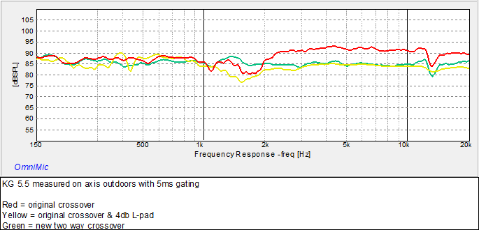
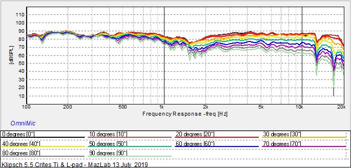
Gents, thanks for your encouragement. Really appreciated. I have learnt most of what I know about audio from great forums like this one. If it weren't for all the generosity out there I'd still be tweaking blindly. I post this work as a way to give back. If I can save just one pair of KG's going into the garbage I'll feel rewarded. On that note please do let us all know if you try any of these tweaks. What I do here suits my ears and maybe not yours. Let us know either way. Outdoor polar measurements - original crossovers Vs original + 4db L-pad mod Vs Stage 1 upgrade: Just a small update - I did some full horizontal polars of the KG's with original crossovers and with Lpads outside last weekend at the same time as I measured the new Stage 1 two way design. These were done with the speakers hoisted up about 1.2 metres off the ground which helps give cleaner measurements than inside due to less room reflections. The Lpad tweaked measurements that were provided previously were done indoors, these should be a bit more accurate. I think these are good reference points for changes going forward. 🧐 Curves: Original KG crossovers... Original KG crossovers with 4db Lpads…. Stage 1 Upgrade Crossover.... Polars: Original KG crossovers... Original KG crossovers with 4db Lpads…. Stage 1 Upgrade Crossover .... Looking at the 4bd Lpad polar it was interesting to reflect on my earlier comments in the beginners mods section of this thread about how the Lpads seemed to bring up the bass. Here you can literally see the heat (red) in the 2khz and below coming into the response picture. The take away for me is to trust my ears, they seem like an accurate gauge of my preference for a flatter response! Cheers.
-
Hi Pjstone, thanks for the encouragement! I have the Omnimic. I was going to get something cheaper until I watched this by 123Toid. I also got DATS V2. Once you have these two tools then XSim is the glue that enables it all to come together. The XSim thread has a lot of how-to info and Ryan at Impulse Audio, designer of many DIY Sound Group systems has this nice tutorial (and a more advanced Part 2) and many design walk throughs where he shows how he uses XSim which is very insightful for its operation and the subtler aspects of crossover design. 123TOID also has some great XSim tutorials on various facets of crossover design. Stage 2 Crossover - 2.5way V0.1 (blue) vs V0.2 (grey) frequency and phase. Only showing the effect of changing the 0.5 config (I didn't bother to change the L-pad on the tweeter to bring it down).... The author of Xsim is Bill Waslo. Same gent that developed Omnimic for Dayton Audio, SynergyCalc etc. The work he has done for us DIYérs is amazing. Getting to know his work a little better has fed my addiction. . Would love to build myself some synergy horns (Danley style) one day for my ultimate HT build!
-
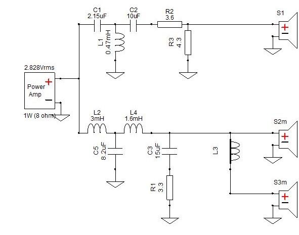
Another minor update. Refining the Stage 2 crossover 2.5-way upgrade design. Looking closely at the JBL DD66000 crossover schematic mentioned in a previous post opens another approach to the implementation of the 0.5 circuit leg of the Stage Two 2.5way design. Tweaking my previous Xsim design (I'm calling the "2.5way V0.1") I have come up with a modified (V0.2) design that realises about 2db more efficiency from the woofers by connecting L3 directly to positive. C4 and R4 are optional as they have no affect on the frequency response, but can be added to smooth the impedance. This additional efficiency from the lower woofer is easily matched by adjusting the value of R3 which acts like a volume control on the the tweeter level. Here is a comparison of the difference between the V0.1 (blue) design and V0.2 (grey).... The left-hand axis of this graph is zoomed in here to 2db increments. This shows the other benefit of this V0.2 design is a slightly smoother response, with the KG's now effectively no more that +/-2db from 200hz to 13khz, or 18khz if we are able to forgive that 1khz wide notch . Also, I have not included phase above because removing all of the low pass section from the lower woofers signal path has zero effect on its acoustic phase. And here is the impedance graph. Electrical phase is included here, this shows 2.5way crossover V0.1 (blue) with the impedance peaks up around 30ohmns effectively addressed by the optional C4 and R4 on the lower woofer circuit (grey). Tune these to your taste or omit. And for comparison here's the measured Stage One 2way design (red) vs the simmed Stage Two 2.5way V0.2 (blue) both without smoothing.... Frankly, I'm really excited about this result and am very much looking forward to building up this design! New Xsim V0.2 .dxo attached. 2.5way crossover V0.2 (.5 to amp).dxo
-
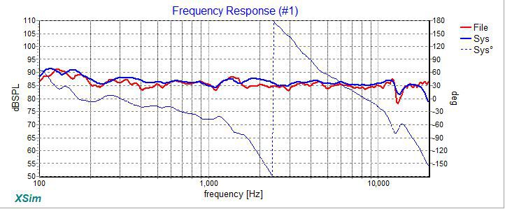
Another update on the journey. Stage 1 Crossover Upgrade - design, build and measurements. I played with my crossover design for an improved 2way and made a few tweaks (new Xsim .dxo attached): Simulated response looks good, woofer (green) breakup is now 10db down: Impedance never drops below 4ohmns... For this modified 2way design I simply cobbled together some extra caps, inductors and changed the resistor. Here is the crossover. The little green cap is added to a 15uF to make a 16uF (parallel caps sum values) and the original 2ohmn resistor is swapped out for a 1ohmn..... The little brown cap is soldered across the original 8.2uF (which is on the other side) to make it 9.1uf.... And the 1.1mH coil is soldered into the positive woofer lead hole (+W).... whilst the woofer lead is simply soldered to the other end of the coil.... On the other side of the crossover board I swapped in a 1mH inductor in place of the original.... And finally, where would we be without an L-pad for good measure.... Simple, quick and cheap, perhaps $10 per speaker in parts seen here, sky's the limit if you like high end crossover parts that wont measure any differently! 😉 If I end up with this design in my KG's permanently I'd stick everything down with hot melt glue and cable tie the inductor to the board. Done! The moment of truth. Here is an overlay of the modelled and measured response on axis. The measured Red curve is without smoothing, Xsim applies 24db/octave smoothing by default to the modelled driver (Blue) curves. I'm blown away by how accurate Xsim is: Here next is a comparison of original crossover (Red), original crossover with 4db L-pad in yellow and new crossover in green. I'm calling this a win for the new Stage One 2way design. Here is the polar from 0-90 degrees off axis: Here is the Dr Geddes style polar, not perfect but a big improvement over the original through the crossover region. Easily tweaked using the .dxo file attached: For context. Horizontal polars are measured by rotating this turntable: But! Lets look now at the vertical off axis. Here is the vertical in the upward direction: Here is the vertical in the downward direction: So I believe this shows that the KG's in a 2way configuration are not too tolerant of being vertically off axis with the horn. Those big suck outs in the crossover show the effect of the forward vertical lobe. If you stand/sit in front of them off axis vertically, depending on how close you are, you may not be hearing these lovely ladies at their best. And I want them to be dressed in their best! Vertical measurements inspired by Wayne Parham, note the compass taped to the side of the enclosure at the level of the horn: And for completeness here's the verticals of my tweaked 2way design and the original crossover, very similar off axis performance suggests the suck out is acoustic rather than electrical: It will be interesting if a 2.5way improves the range of angles before the big cancelation suck outs occur - watch this space. 2way crossover.dxo
- 58 replies
-
- 2
-
-
- cabinet bracing
- crossover refresh
- (and 4 more)
-
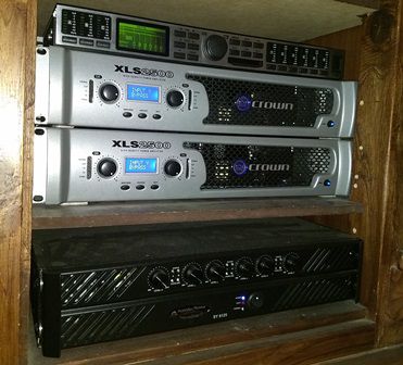
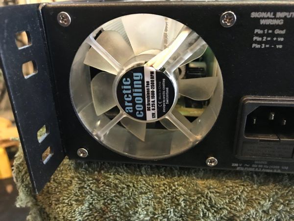
Crown XLS = Light, cool running, quiet fans, RCA inputs, POWER, clip limiting saves voice coils on subs; transparent sound, almost no hiss even on high efficiency horns, cheap! For Aussies, Australian Monitor SY series, all of the above but HEAVY and needs a fan mod for home use!
-
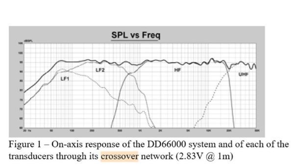
Hi Glens, Actually it wont affect the phase much at all, on the measured axis. Have a look at my sim here with phase added. Original crossover response graph now with phase curve switched on: Now I can remove the effect of L3 (the .5 part) using the short function in Xsim (denoted by the thick line through L3) on the bottom woofer to bring this crossover back to a 2way: Here's the new frequency response and phase: Overlaying these for a side by side makes the difference easier to see: Green = 2way; and Grey = 2.5way. What I'm aiming to do here is described far better in the literature for the JBL Everest DD66000 where they describe the ".5" augmentation approach of that magnificent design on page 11: "A second 1501AL operates in the bass frequency range from below 30Hz to around 150Hz, where it is rolled off at a gradual 6dB/octave. The first-order slope ensures proper amplitude and phase summing between the two woofers over their total operating range. Both woofers operate below 150Hz, but only one of them extends up to the 700Hz crossover point. This is done to achieve proper directivity control throughout the entire woofer operating range, while delivering powerful and extended low-frequency performance." Now this graph looks familiar, also from page 11 the .5 is applied to LF1: On page 18 they say: "The design intent is to use both woofers in the bass frequencies and slowly transition to a single woofer in the midrange. This technique allows a primary crossover point between just two drivers (i.e. LF2 and HF) and permits proper control of the directivity pattern of the system, while providing tremendous power and air movement capabilities at the lower frequencies. " So how to roll off the KG's second woofer at 6db per octave? Add a single coil to create a first order (6db) transition out. See here the JBL service manual for the DD66000 which sets out the crossover design in complete detail. If its good enough for the Everest, it should be good enough for the KG's? One of the many great things about Xsim is the crossover design file contains all of the measured driver data. You can pick up the latest release of Xsim here over at diyaudio.com and have a play with my crossover design .dxo file now attached. Anyone think they can improve on this? Go on, I dare you to have a try! If you can improve it we will all benefit. Cheers, Maz. 2.5 Way Crossover.dxo
-
Hi Georg, Thanks for the tip off to your thread and I'm so glad you're having some fun with the KG's too. Certainly my work on the 5.5's here is directly applicable to your 5.5's. Also the cabint bracing, acoustic stuffing and other minor tweeks will most likely work on the rest of the KG family too. With regards to the crossover work, each speaker is a unique design unto itself and would require individual measurement to know what works. Therefore I would not think that the crossover changes I've proposed for the 5.5's will work with the rest of the KG family. If you have a look at Troels Graveson's site you will see there what he has to say about this matter. I tried to use an existing SEOS design but substituted in a different tweeter compression driver that purportedly was interchangeable because the original unit specified is no longer available. Suffice to say that did not work out as well as I'd hoped and a complete crossover redesign was required. Notwithstanding, any changes you make are reversible so I say why not have a try and see if you like what you hear. You may learn something along the way! Hi Glens, Because I have measured on axis with the tweeter I have designed the crossover to set the phase correctly in that direction . In my case when I sit on my lounge my ears are at the same level as the tweeter so this is how I have measured and designed the crossover. If you have a play with XSim you can see there you to adjust the relative acoustic offset of the drivers which sets the phase and forward lobe. What this means is that the response should be uniform off axis in the horizontal plane. However in the 2way configuration the vertical axis will have a very narrow region where the drivers are in phase because (as I understand the physics of the matter) the distance between the tweeter and lower woofer dictates that the forward lobe will be very narrow when that lower woofer is called to play up to the crossover frequency. There is a great video by Wayne Parnam the designer of the famed Pi Speakers which demonstrates the concept of the vertical forward lobe and its importance to power response. Also Audioholics has done a thorough write up on the problems with the two woofer design many centre channel speakers have (same problem, different orientation) and how this affects response. These nulls are in fact (if I'm not mistaken!) all phase related which are effectively dealt with via the 2.5 way approach that JBL and other manufacturers commonly use.
-
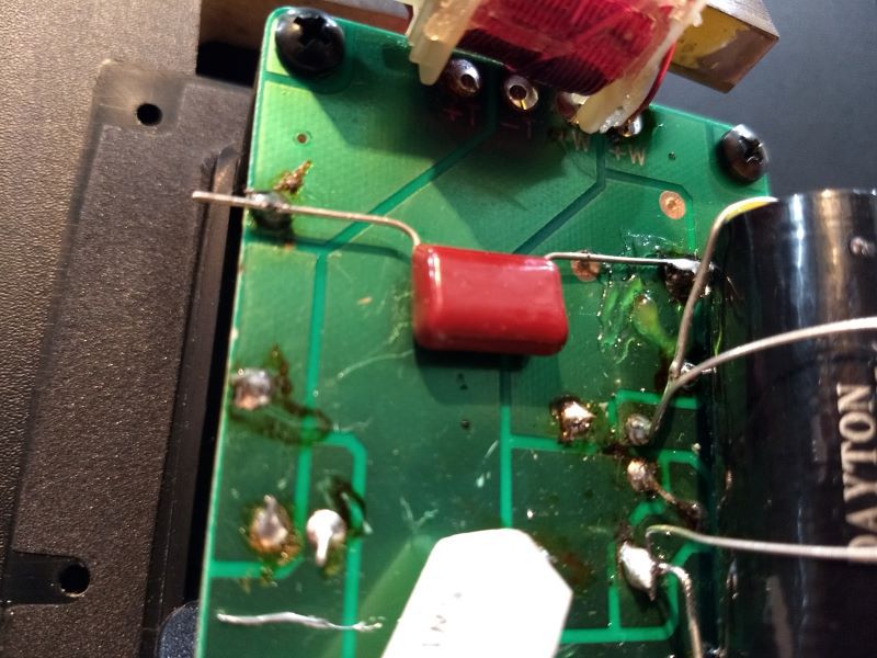
Hi Georg, First let me say I wish I could speak German as well as you can speak English! Second, I'm so glad you got some value from my long rambling and rather unscientific write up. At least you understand why I was compelled to do so. 😉 Next let me say that I am really intrigued by your printed PCB's as my current efforts with wood leave much to be desired (yes that is a happy stick figure by my 6yr old under that 10ohmn resistor) ..... One small error I noticed in your first post is that you say the KG 5.5 woofers are series wired when in fact they are parallel. This is important as it will change the performance of the crossover and overall system efficiency and impedance. I have had the great pleasure of working alongside some of your countrymen in Aus Georg, and if there's something that I really admired about them was their appreciation for precision. If my stereotyping is correct then you may want to invest in the Omnimic and DATS tools which will enable you to accurately measure all your speakers to really know how they are performing. Then its a relatively easy matter to model the existing crossovers and improve or alter these. Before (or after 😊) you lay down your hard earned cash for measurement equipment there are a few choice sites around the web I would like to recommend to expand your knowledge a little, if I may: Zilch's crossover design thread "Flex your PCD Mettle" (PCD = Passive Crossover Design) is a wonderful place to start with all manner of jump off points to the fine art of crossover and speaker design which inspired my own SEOS based design. Paul Carmody's website is great for the beginner with some detail how to's and interesting designs includiong the famous Overnight Sensations. Troels Gravesen lives just up the road from you in Denmark (everything is just up the road in Europe if you live in Aus!) and he does some really special builds. He also details his approach to upgrading some classics which I found very useful for my work on the KG's. I think I spent a month reading everything there. Good stuff. Wayne Parnam from Pi Speakers in the USA has some terrific white papers on crossover design basics at the bottom of this page. He is so very generous with his knowledge and very responsive to requests for information on the Audio Round Table forum. His original inspiration also came from some Klipsch speakers! The XSim thread over on diyaudio.com is also a great source of how to do crossovers, particularly with XSim obviously but there is good discussion of the principles there too which are essential knowledge. I have had support there from Bill Waslo the designer of XSim and the Omnimic system, amazing! The Omnimic user documentation is a great resource as it explains how to measure loudspeakers which is the key to "seeing" what your speakers are doing and the gateway to empirically improving them. And last but not least Dr Geddes white papers are foundational and useful for sifting the Audiophile from the Audio-fool! Finally there are a few talented and generous speaker designers that have posted how to videos on speaker design, measurement and crossover modelling: My favorite is Impulse Audio. Ryan is the designer of many of the superb diysoundgroup.com kits. Closely followed by 123Toid. Good luck and keep us posted! Cheers, Maz.
-
KG 5.5 all measured with DATS V2 in the original enclosures without crossover. tweeter.zma Parallel woofers.zma KG 5.5 tweeter.pdf KG 5.5 woofers parrallel.pdf KG Upper woofer in enclosure.zma KG Upper Woofer in enclosure.pdf KG Lower woofer in enclosure.zma KG Lower Woofer in enclosure.pdf
-
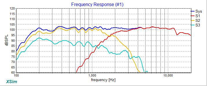
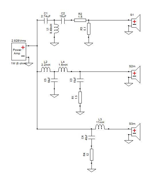
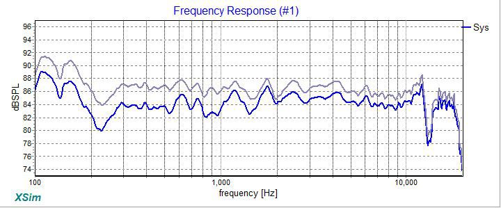
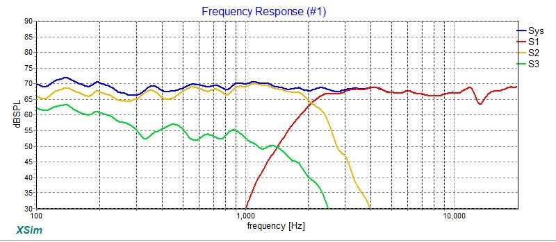
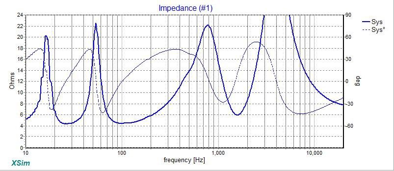
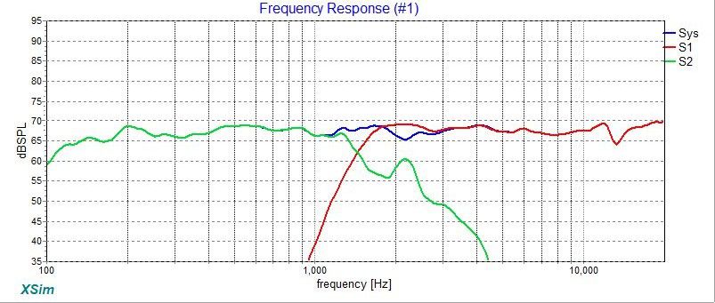
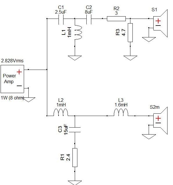
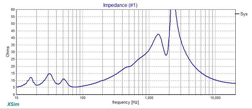
Dear all, Another update on the KG journey. In the long time since I've made a substantive update here I've been doing all the reading I can about horns, so compelling is the sound of these great speakers, to understand why this should be. This led me to the enormous and richly informative Econowave thread over on AudioKarma documenting the collaborative efforts of some real greats in the audio world, principally Zilch, who despite sadly passing some years ago, his endeavours are kept alive by the lively gang over there. Over the two and a half years since the KG's came into my life, I've leant enough and purchased some proper measuring equipment (Omnimic and DATS), that now I'm able to empirically measure the KG's and be a bit more scientific about what I've done recently. The Omnimic measurements I've been able to make show that in original, unmodified form: The KG's are hot on the top end, no secret there; and The 2 way crossover configuration with the woofers wired in parallel means that there is measurable lobbing, or destructive cancelation between the woofers that is entirely typical and expected. Beginner updates quantified: First I want to share is how the KG's measure with all of the mod's I've documented here so far, principal among these being the effect of the 4db L-pad modules. The following frequency plots both show exactly the same data, that is the KG's measured at 1 meter with 5ms gating, on axis and all the way around to 90 degrees position off-axis, in 10 degree increments. I have done this to ascertain both on and off axis horizontal response to get a feel for the totality of the output which is also called the sound power. In the graph above we can see that the on axis response is remarkably flat (other than the 1 - 2.5khz range) for what was essentially a stab in the dark effort with the 4db L-pad module. At this point I'm thinking my ears are great at picking a flat response. Nice one ears! Taking the same curves we can easily display a polar map using the fabulous Omnimic software/microphone combo from Dayton Audio. The main positive take away here for me is that the horn/waveguide of the KG's is constant directivity. This is a REALLY BIG DEAL! 😁 At this point, if you are even vaguely interested in horn/waveguide loudspeakers (this is the KLIPSCH forum afterall, so believe me you are, but just may not know it yet! 😉) then you owe it to yourself to read Dr Geddes whitepaper on waveguides to understand why this polar graph is so important and how to read it! Suffice to say once I saw this I knew why the KG's are so magic, but they can and should be better! That dip at the crossover region is not good and is the subject of my attempt at improved crossover designs, called Stage 1 (a 2 way minimalist tweak) and Stage 2 (a 2.5 way complete makeover). Unmodified KG 5.5 measurements: Taking a step back first, if you have an unadulterated pair of KG's then this is the response of the system with the original crossovers simulated in XSim using the raw driver measurements in the KG enclosures. Yes, that treble is really HOT! The other important thing of note is the big woofer (green line) suck out at 1khz. That is occurring because this is a two way with two woofers playing the same frequencies. Not good. The following graph shows the two woofers playing on their own (green and blue lines), no crossover measured in the KG enclosure at one metre with 5ms gating. The individual woofer responses look quite smooth. However the red line, with both woofers playing wired in parallel as they are in the standard crossover, (i.e. the green line in the previous graph) we can see the same big destructive suck out from roughly 1.5 - 2.2khz. That double bump after 2.2khz are the woofer cones losing linearity and is called break up which I want to completely avoid if possible. Here is the original crossover schematic copied from here on the forum into the wonderful free XSim design software. Technically what we have here is a third order highpass on the tweeter and a first order lowpass on the woofer with a impedance correcting shunt or Zobel (C3 & R1) on the woofer: Crossover upgrade time: So I would like to offer two crossover upgrade options to deal with these problems: Stage 1 - a minimalist 2-way tweak: This crossover aims to do the minimum and alters the: tweeter (S1) circuit a little (at L1) and adds an L-pad (R3 and R4); and woofer (S2m) by adding an additional inductor (L3) and nudging the C3 and R1 values. The simulated response is a big improvement (if I may say so myself), but the woofer (green line) breakup bump is only 5db down and affecting the system response (blue line): And finally the system impedance: Stage 2 - a complete 2.5-way redesign: Here everything is a new value and this design adds a new additional inductor to the lower woofer (S3m) for the .5 in the 2.5. Personally I think this more complete redesign will reap improved off axis (polar) response which will reward the listener with a more consistent sound stage. This is a slightly more complex design that completely removes the nasty breakup lump at 2.2khz and flattens the response through the crossover and overall. And the system impedance: From here I need to build up these new designs and measure the KG's with them installed. This may take a while because I have three kids and a full time job but I'm on a mission so I'm excited to see how much improvement I can get from the old girls yet! Rest assured when I do I'll be sure to post up the results and would welcome any and all feedback. It's all a journey afterall.
- 58 replies
-
- 1
-
-
- cabinet bracing
- crossover refresh
- (and 4 more)
-
As much as I like the look of center channel speakers they are, by design, highly flawed. See here this detailed Audioholics report with measurements that really clearly demonstrates the folly of the horizontal layout and the benefits of using a regular speaker for center channel duties. If I had Fortes with their controlled directivity and imaging, I'd not bother with a centre at all.
-
 angelluisg - Epic system. Next steps? Easy: Measure; Optimise & integrate; Invest in more ultra low frequency capability; and Enjoy!
 -
Best Centre Speaker for RF-52 II Floor Standing Speakers
Maz4bz replied to James W's topic in Home Theater
"Best Centre Speaker?" Not a centre speaker! As much as I like the look of centre channel speakers they are, by design, highly flawed. See here this detailed Audioholics report with measurements that clearly demonstrates the folly of the horizontal layout and the benefits of using a regular vertical speaker for center channel duties. I've switched off my horizontal centre channel and I haven't missed it. If I could get an acoustically transparent screen in my room I'd put in a normal vertically arranged speaker and switch my centre channel back on. Hope that helps. -
I'd be using all three subs - more subs = smoother bass. See Dr Geddes write up. He did a thesis on the matter. Its really hard to over invest in bass headroom, especially in a high efficiency system like yours. The SW-311 looks to be the best. Being passive radiator it's compact and should be able to fit in to a range of spaces which increases your chances of finding the best (least bad) modal location for it. Keep it! Your 12's may be old, but should be terrific. If you have the inclination to get the best performance from your system its dead easy and this is how I got started at it. You can use your Audessey or MACC (pioneer) AV receiver mic and the free Room EQ Wizard software. It's very empowering to be able to SEE what your system is doing! As much as I like the look of center channel speakers they are, by design, highly flawed. I would press one of you spare regular speakers (RF-5 would be amazing, room permitting) into the center channel role. See here this detailed Audioholics report with measurements that really clearly demonstrates the folly of the horizontal layout and the benefits of using a regular speaker for center channel duties. Beyond that you are going to have a great system I believe! Even a modest receiver will be able to get you to reference levels (subs permitting). Enjoy!
-
Lobing? I've switched off my horizontal centre channel and I haven't missed it ..... https://www.audioholics.com/loudspeaker-design/vertical-vs-horizontal-speaker-designs If I could get an acoustically transparent screen in my room I'd put in a normal vertically arranged speaker and switch my center back on.
-
Thanks for the comments gents. I've really enjoyed my 5.5's. I say whatever works for you is good. I think bracing and insulation for the cabinet and tweeter L-padding, for my ears, were all essential updates that this system deserves. Enjoy!
-
Maybe this might help... Geddes on distortion
-
I'm I bit late to this party so sorry for the late entry here. I did my KG 5.5 crossovers and I heard no real improvement. Biggest bang for buck was taming the tweeter with some "Lpad modules" and bracing/dampening the cabinet. I believe the KLF 10 and KG 5.5's are closely related so you may have similar benefits?
-
I really love my KG 5.5's. I've recently built a SEOS based design with Faital Pro 12" woofers. I've been listening to these for a few months and I've just swapped the KG's back into my system now and wow! Amazing! Chest rattling bass feels so good. I imagine the 5.2's sound just as great, perhaps just a tad less efficient. I assume might also benefit from some taming of the tweeter as described in my write up about this?
-
I think Zilch would approve. Besides, if you can and its fun, why not? You might just learn something along the way... If you buy a measurement mic and post you're results you'll get better insights and help on what's actually changing. Thanks for sharing 😁