


Droogne
-
Posts
234 -
Joined
-
Last visited
Content Type
Forums
Events
Gallery
Posts posted by Droogne
-
-
Driver simulation will be for a 80-150hz range. Yes this a very narrow range, but it's still in the LaScalas hornloaded range and I already have them. I might use completely different cabins, but the simulations will tell me if I actually have to.
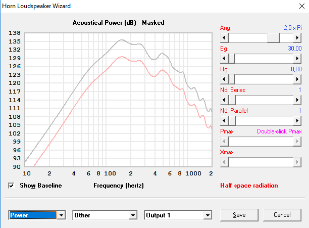
Em Kappa 15A: Xmax limited output at 80hz (0dB), 2pi.

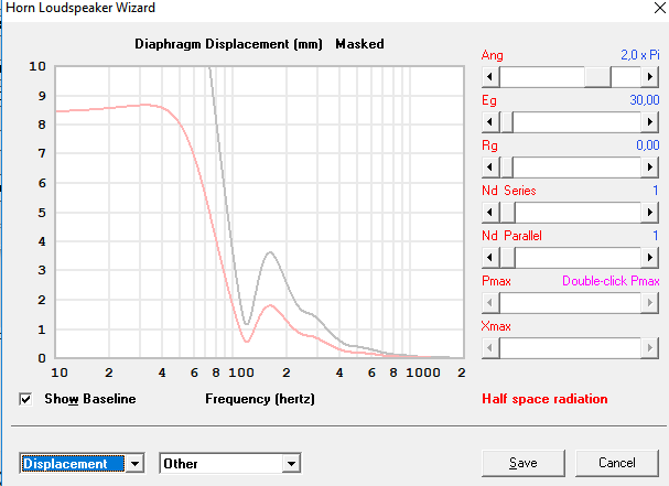
Reason for modelling can be best shown with a displacement graph showing the Em Kappa 15A at 80hz:
It's clear displacement skyrockets around 120hz.. I actually need a -3dB or -6dB point around 80hz, which is easy with the natural roll of this setup, but I need more displacement to allow the driver to be used fully down to 80hz.
At this Xmax limited 80hz point I would end up with a 125dB (-3dB) or 128dB (-6dB) lever from 110hz and 130 respectively.
And yes, 80-150hz is a narrow range, but it does mean 2 things:
1. using more of the hornloading the LaScala provides
2. Being able to stack the LaScalas when lowering the 150hz to 143hz. 1/4th WL of 143hz is 60cm, which is the exact distance between the acoustic center of a pair of stacked LaScalas. Acoustic coupling will increase the output with an extra 3dB on top of the +3dB from doubling the amount of bins. So +6dB total extra output.
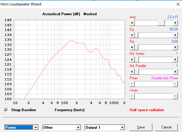
=> a stacked LaScala pair loaded with a Eminence Kappa 15A would result in a 128dB level at 80hz, and 131dB at 110hz (which will be the level where I will flatten the response to actually be within 3dB of 80hz).
For my project I needed 135dB at 80hz, so it's pretty far away from this. It looks like the displacement will be the deciding factor in the output at 80hz. Using a -6dB crossover point might also help. If the Em Kappa 15A would be able to be used at its full RMS power the output would be 128dB at 80hz! So 134dB for a pair, which is almost exactly where I need to end up.
-
15 hours ago, Edgar said:
Thanks man!
Here is the output of my LaScala loaded up with an Eminence Kappa 15A driver, simulated to hit it's Xmax (4mm) at 60hz, which is at ~20% RMS (17.5V, instead of the Em Kappa 15A 60V). 60hz is a cutoff I regulary use in home. In home I would apply a lot of EQ to flatten it to this 60hz, so output will be limited even more in the higher ranges. I used 2pi for better comparison with the following simulations.
Here is the same driver mounted in a sealed cabin with same volume as the LaScala sealed compartment, also Xmax limited at 60hz (19V input):
There looks to be around 3-4dB hornloading in the 60-100hz range, and 6dB in the 100-500hz range.
-
14 hours ago, PrestonTom said:
I would not dismiss the La Scala so quickly. It does many things well (given the foot print and size...).
Please remember that HornResp is a model and not reality. It is very useful for the builder to plot the inside path length and the outside path length. This disparity points to where the low pass roll off will be (it is not the driver ....). I did this, painstakingly, for the Jubilee. It is very informative!!!
HornResp is a powerful tool, but there are some things that need to be highlighted: dispersion, path length differences, loading from the room (floor, walls etc). Keep these in mind when you do your modeling.
Good luck,
-Tom
I will not neglect them. It's more for driver simulation than for anything else so I'm good I think.
-
15 hours ago, moray james said:
Ha LaScala is not a bass bin it starts to roll off at about 140 Hz. and should be crossed over to a bass horn at 80 or 90 Hz. for best results at the bottom end and 350 - 400Hz. at most on the top end. It was not designed as a bass horn below 80 Hz. it acts just like a leaky box. This should not in any way be taken as an indictment of the LaScala it is simply telling the op what a LaScala was designed to do. At 60Hz. the LaScala has the same response as a Heresy but it will play a lot louder.
I used the word bassbin, but yes maybe mid-bassbin is more applicable. I do realize it's roll of. I have had 8 of them, and measured them multiple times. Now I want to repurpose a few of them, and want to see what kind of woofers I'd need. Also having the hornresp parameters is a good way to evaluate the amount of hornloading (both cornerloaded as in free space) I will get.
-
Anyone who can help me with the Hornresp parameters to model the La Scala bassbin?
Any help is appreciated!
-
 1
1
-
-
How much sensitivity would a compression driver gain or lose on a K402 horn? Looking at matching the woofers with the top and need to know this little bit of info.
Thanks in advance!
-
I do have some ideas I'm gonna work out depending on some other projects (HiFi related), will try to right it out tonight or one of these days! Very busy, as I just started my medical apprenticeships, and I have to pull long 60-70h weeks, with masterthesis, studying and other time-consuming responsibilities in the weekend.
Enjoying audio will probably be pushed to the far background, let alone contemplating and building new DIY speaker set ups..
-
5 hours ago, billybob said:
Cannot recall now without looking but I or other may have mentioned the 600's as they were the rage at Rodney's. OP may have suggested cost prohibitive. Still we discussed future events being always better than the last. @Droogne...thinking things went off well last year. What is happening this time around, please...thanks!
We pulled of using just only 1 bassbin on each side, with an 18" below. 2 tophorns for better diffraction. It was by far a good setup, as I was having exams at the time, and wasnt able to be there during stagebuilding. We had to place them inside "towers" which meant suboptimal placement. Volumewise the single bassbin was able to keep up without a problem (we have a limit of 95db max, and the space wasnt too big). We might try again this year, but I'm gonna have even less time this time, so I will not be able to be there, which is a shame if I lend out my very expensive gear..
-
1
-
-
Hey
Does anyone happen to know the polar control/coverage of the Lascala bassbins? Cant seem to find it anywhere..
Thanks in advance!
-
And listed price is only for horn and driver, or also including the LF bassbins?
-
by saying you are not separating the K942 combo you mean the LF and HF compartiments? Or horn and driver?
-
1 hour ago, PrestonTom said:
It was a Klipsch 942 I believe.
It was built to satisfy some THX requirements on dispersion and size. It was a short-lived model. I never heard one, but I don't believe it was well-regarded.
Only horn I see on the Klipsch 942 is the K402 itself (on a double woofer bassbin). Or is it a real 942 horn specifically?
-
I recently came across this horn, which was described as being a mid-horn from Klipsch, but I dont recognise it. Anybody any idea?
-
Just redid all the PEQ settings I had, and tried something different to measure the delays. I just used the built in "acoustical delay" function in the REW measurement tool. I redid the in/output settings in the processor so the High frequency driver got the left signal, and the Low frequency driver the right. That way it calculated the delays as it would between 2 speakers. Only took me a minute or so to do, without having to change any cables. It also extremely simple to do, and I dont think you can make any mistake interpreting it as it just says "you need to apply .... ms delay". When I applied the new delays I got a totally new speaker! Damn, the voices and intelligibility improved so much!
-
1
-
-
The woofer does seems really high quality, thats true. I also thought it was about the frequency extension and size. Does make sense
As far as I know the retailer I linked, and contacted, did sell them. Doesnt really matter as it doesnt like I'm gonna buy them. I'm happy with the K510 on my LaScalas for now!
-
Any audio experts ( @Chris A ) who can maybe help me decide how to set it all up? Area that should be covered is not very deep (around 8m so 26ft.) , but almost twice as wide. I have 4x P Audio PH4525 and 2x Klipsch K510 horns. For drivers I can choose between 2x JBL 2446 drivers and 4x Faital PRO HF200 drivers. The horn/driver combos will go in seperate top bins.
How would I best stack them? The HF200 can do 500-20 000hz, so I was wondering how I would use 2 on each side without lobbing. Could I prevent lobbing by having each driver carry a different spectrum? So even though they are identical drivers, have one go from 500-4000, and the second one from 4000-... ? Or could I just have both of them do the full 500-20 000 spectrum?
The area to be covered is around 8 meters deep, and 16 wide. So maybe best to no stack them, but put 2 on each side and have them cover a different horizontal region?
-
PS some measurements I found (I think they're from Geddes, not sure though.) Looks like theyre pretty flat to almost 500hz.
-
Also you're definitely not the only one frustrated by the direct radiating in the M2: "
I was quite impressed with the wide dispersion, clarity and neutrality of these speakers when I heard them at an AES Convention a few years ago. Only wished they were not vented. The horn compression driver is an ingenious dual diaphragm design by Alex Voishvillo for extended high frequency coverage and low distortion at high output levels.
Alex Voishvillo, Dual Diaphragm Compression Drivers, AES Convention Paper #8502, NY 2011"
-
I still have 2 huge peaks around the crossover point, but the difference has almost disappeared at the crossoverpoint itself. What is the (probable/plausible) cause of these peaks (@ 870hz and 421hz), and how would I take these on?
-
Well I was thinking the exact same thing. I must say I'm basing a lot on things you told me, but I have been looking a lot at the behind-the-screen models of their cinema line, as well as to the M2, and I did wonder how this direct-radiating model could ever be so superior.. Everyone is raving about it, and I believe that they sound amazing, but why would they leave out the horn loaded bass? It seems like theyre going all out on everything, but neglecting the bass. It is a fact though that the M2 is a studio monitor, and that that could explain the direct firing model no? This way they boast a flat response from 20-20000hz which is something that comes in pretty handy in mastering etc?
That aside. It looks like the best part about the M2 can be bought seperately! (https://reconingspeakers.com/product/jbl-m2-horn-lens-5025594/) . This is without a driver, and is not unreasonably priced, which made me curious. Not convinced. But curious. Still want to go 100% for the MEH.
-
Hey
Seen a lot of good reviews about the JBL M2 studio monitors, and primarily about their horn. It seems they also boast an extremely good polar control. Have you had the chance to hear them maybe? Or have theoretical comparisons between them?
Thanks
-
-
2 minutes ago, Chris A said:
Looks like you need an additional 4 ms of delay, but you have to also look at what that's doing to the crossover region--most of this delay may be due to the crossover filters themselves.
Chris
So youre looking at the min. GD vs the 1/12 smoothed graph? And "by look at the crossover region" you mean the SPL graph? Should I redo the measure, but without active crossovers? Or do you need the crossovers on to see and calculate the delays? Also, if I'm correct I should apply PEQs before calculating the delays right? So measure with xover and PEQ, calculate the delay, and then do another sweep to see the influence on the crossover region?
Also, on a side note. What is a good end result for a SPL graph? 6db over the whole region? Thats where I'm at right now (with PsychoAcoustic smoothing). I was at 9db before the PEQs. I also have a few PEQs over to make that 6db a bit narrower (there are 2 "big" dips/peaks I think I can effectively correct), but first I want to get the delay right.
-
Been rereading through it, and I tried to implement it on some of my readings. Tried this out in particular: some quesitions in bold.
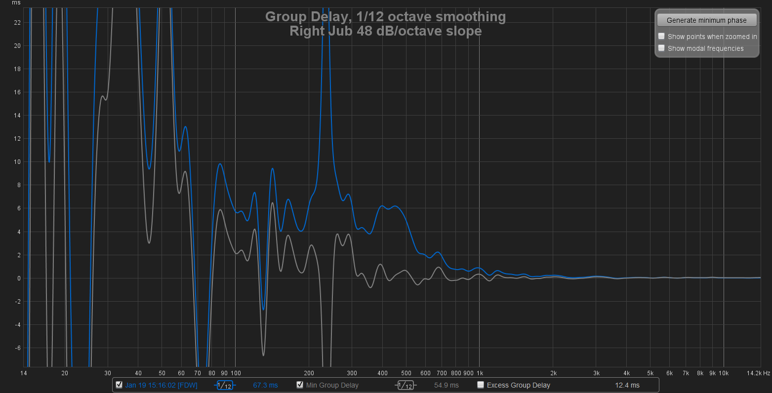
On 4/2/2018 at 6:02 PM, Chris A said:Here is a group delay plot of a Jubilee showing the effect of the steep slope crossover used (48 dB/octave) without sufficient delay being added back to the HF channel to bring the bass bin into time alignment with the K-402/TAD 4002 channel. Note the rise in "excess group delay" relative to the minimum phase group delay going from right to left at the crossover frequency of 475 Hz. (is it possible that you didnt toggle the excess? Or did you mean the "1/12 curve"?) The rise in excess group delay is exactly equal to the time misalignment--about 4.7 ms--in this case due to the change in crossover filter steepness without paying attention to the time alignment issues that the steep slope filter introduced and was not corrected via added HF channel time delay:
Chris
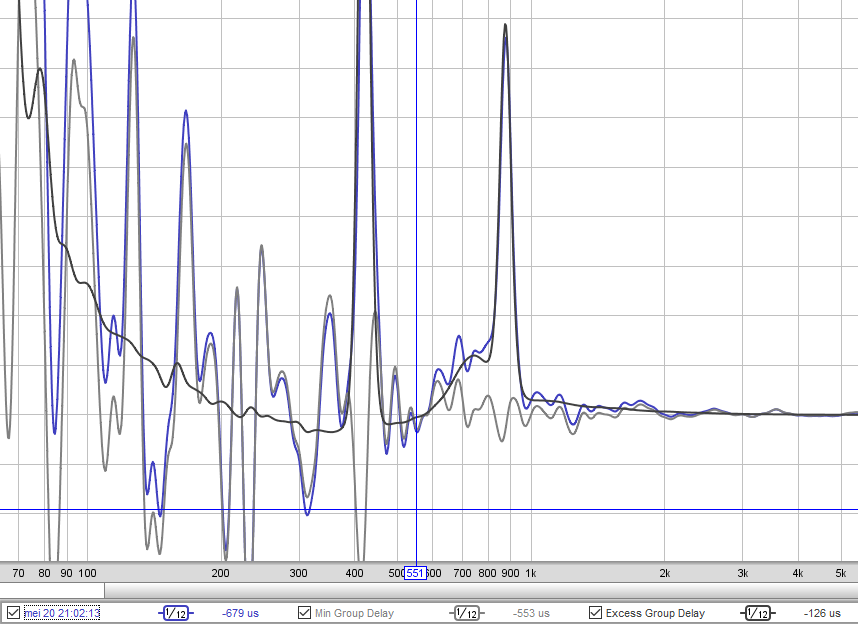
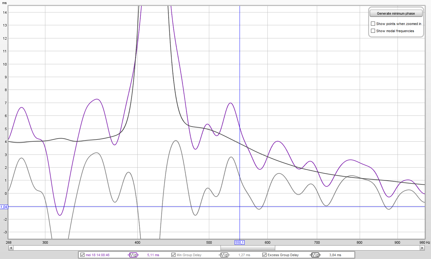
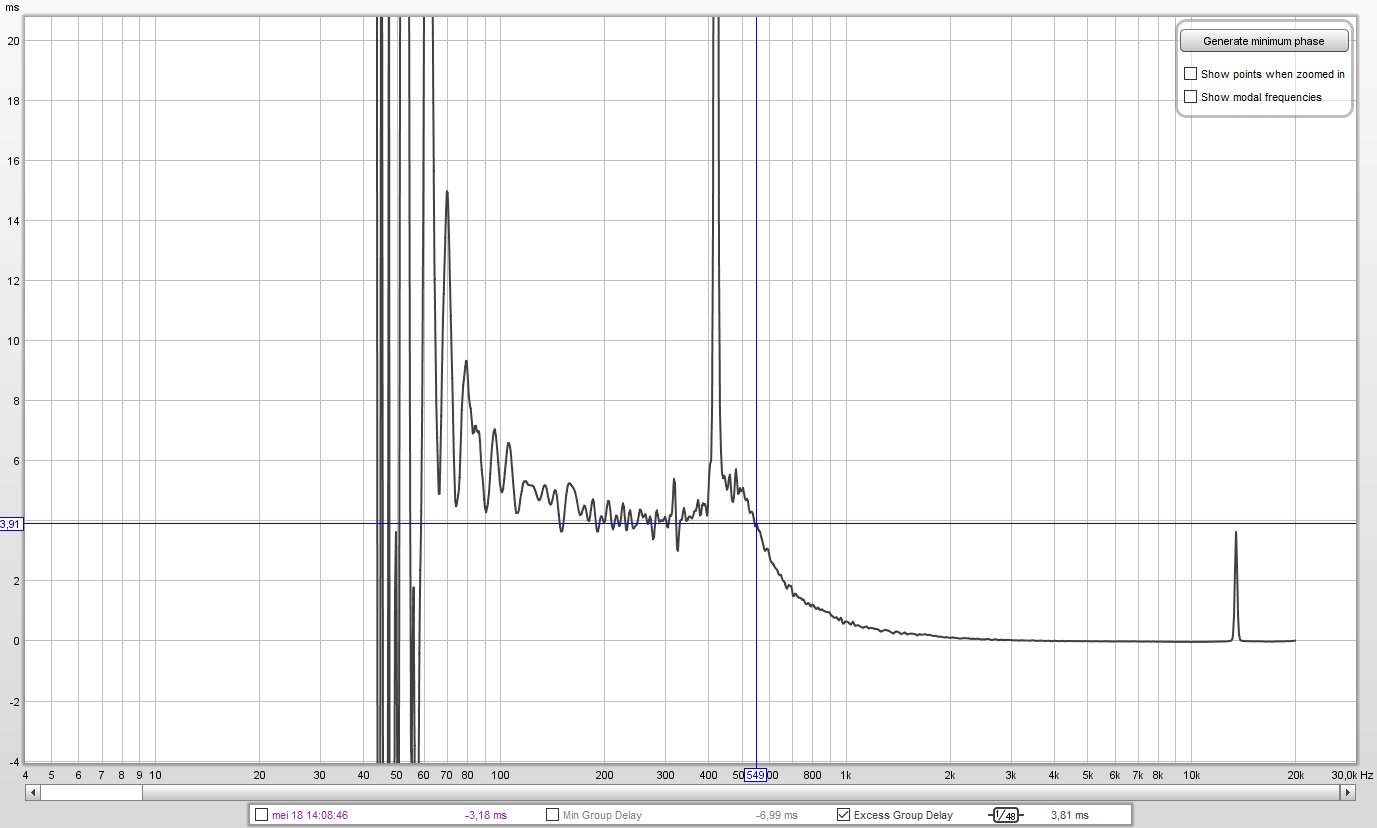
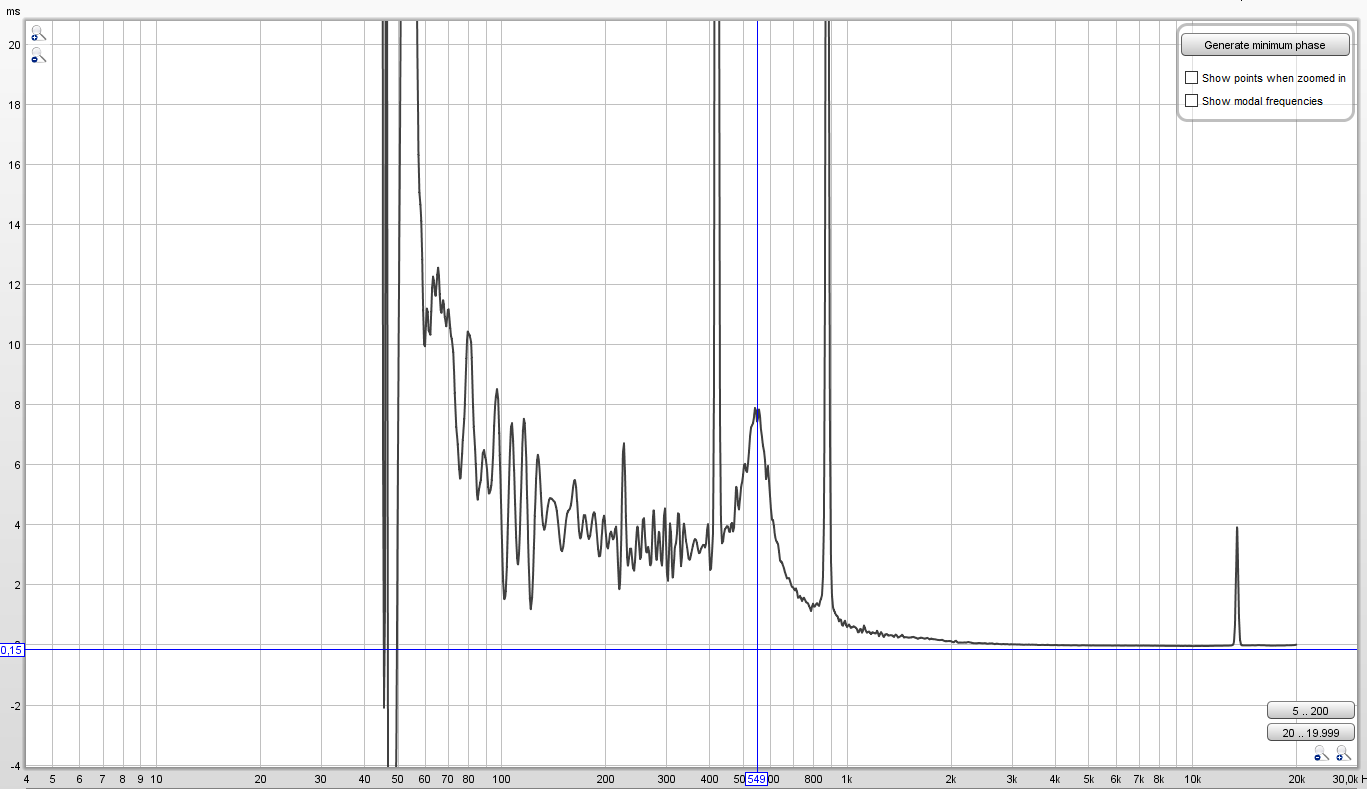
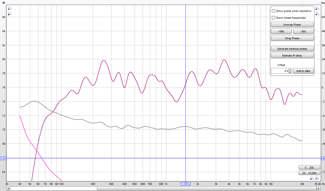
So not sure which graphs to look at. But here are the results of my measurement done on my Center LaScala (PH4525/Faital HF200). EDIT: these are sweeps with delay or PEQs.. I'm not able to do readings right now, so I'm gonna leave them here for now. It's more about the theory behind it, and knowing I'm doing it right. I do however have one reading with PEQs and an improvised delay (same as the K510 LaScalas). At my crossover (550hz) I come at these results:
does this mean a 2,57ms delay on the HF channel? (I subtracted the Minimum GD from the Excess GD). Or am I wrong / is it not as simple as that? (EDIT: I come at a 7ms difference on the PEQd channel... I'll include the FR and GD graphs below here too.)
This is the excess delay as you also showed it:
PEQd channel:
1/48 smoothing
Psychoacoustic smoothing

.JPG.18bcfc6eac1d2103249c04db913e3f8b.JPG)
.JPG.8850bd55d086fa7e30c33b37879786ee.JPG)
.JPG.8c90ba90189b0273185660a5f7c34342.JPG)

La Scala bassbin Hornresp parameters
in Technical/Restorations
Posted
EDIT:
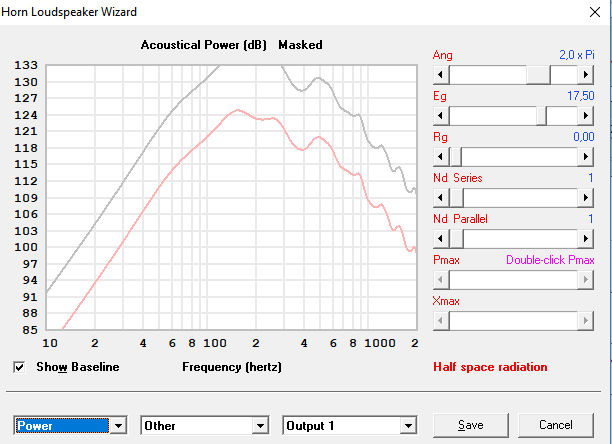
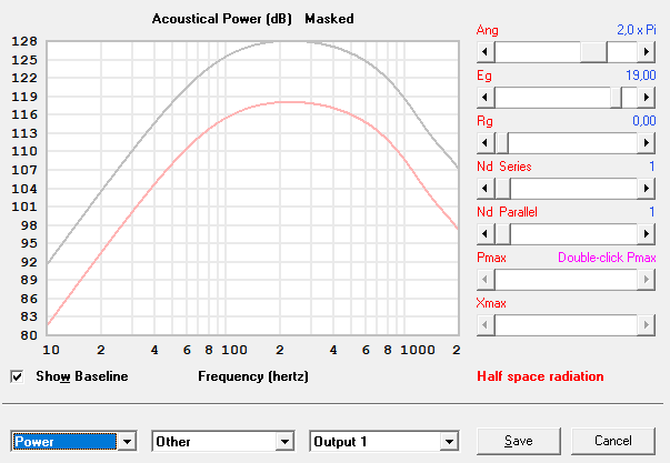
I forgot to include the larger horn mouth when coupling the LaScalas. Modelling this by going from 2pi to 1pi allows for more hornloading into the lower ranges which significantly flattens the response at 80hz. Using the drivers in parallel and the appropriate RMS to reach the Xmax limited output at 80hz I get this response:
This looks already way better! Almost the 135dB I require. Might model some more woofers to achieve even better responses (with lower displacement at 80hz for better sound quality).