


Danieln
-
Posts
43 -
Joined
-
Last visited
Content Type
Forums
Events
Gallery
Posts posted by Danieln
-
-
There is a Part 2 !
http://www.x3mhc.no/dokumenter/SE-v-PP-Part2.pdf
Quite interesting stuff about low listening level PP with respect to hysteresis curve induced distortion.
Anyone with high efficiency speakers will fall in this category most of the time.
The first watt matters most, and this is where Push-Pull design relatively lacks the more.
-
 1
1
-
-
But Mark, you are right in the sense that in the absence of the swamping resistor, the amp will effectively see an easier load (40 ohms in many of the old klipsch xovers). it ensue that in the presence of the said resistor, the amp will work harder compared to when there is no resistor. And as you are pointing, some energy will be absorbed by the swamping resistor.
The thing is that the swamping resistor (Which we should name an impedance matching resistor) is there to accommodate higher output impedance amplifiers who will have their amplitude perturbed by a high midrange impedance. Simple ohms law in fact that can easily be demonstrated.
Dan
-
Marvel is right, the swamping resistor is only there to make the midrange an 8 Ohms speaker, as the tweeter and the woofer already are.
Dont worry, if your amp is able to generate 3 watts at 200 Hertz into 8 Ohms, it will also do it in the midrange with the same 8 Ohms without sweating.
Regards, Dan
-
Deang, ever heard about a Zobel??
Hint...it is used to nullify the VC inductance when required.
If I remember, ALK used one of them in his Forte crossover , and other design.
On the other hand, in another one, he states that he utilizes this inductance as part of his filter.
It's there and cannot be ignored.
-
John, thanks for the factual post. My goal is to understand.
Basically you state that in order to get rid of the big 2000 Hz bump, the crossover must be lower in order to get enough attenuation at 2000.
You propose around 500 Hz, which make sense. But in this case, the crossover will be stated to be @500Hz.
Speaker's acoustic output is proportional to electrical signal that drives it.
So when I measure voltage at the electrical crossover, that must be reflected in the acoustical response.
The fact is that I measure a lower electrical crossover with the 2.5mH on my crossover.
It is quite an easy measurement to do using an AC voltmeter and tone generator.
So do you propose that electrical and acoustic crossover frequency are not the same?
-
Wrong crossover. You can run any amp on a constant impedance one :-)
-
Mark, I consider the ALK crossover in high regard.
Mine is inspired by his work. But as you noted, I slightly modified, simulated, constructed and measured the result.
My hearing is not so good, so i will trust a good design methodology and measurement over my hears anyday :-)
I cannot stress enough that you need a constant impedance network with Single Ended Triode (SET) amplifiers or even more so with pentode (without feedback). The key is the damping factor, or say another way the amplifier output impedance. The worst offenders are the original Klipsch networks. The midrange is boosted by several DB without controlled impedance, but is flat with a constant impedance network. been there, done that!
Dan
-
Thanks Mike, i don't remember exactly which one is which, but as you noted it shows the phase shift.
i strongly encourage you to try and confirm the measurement. You don't really need a scope, just an AC voltmeter.
Use "onlinetonegenerator dot com" to drive your amp.
I'm jealous of your K-horns , but in my case haven't corners to put them in.
Dan
-
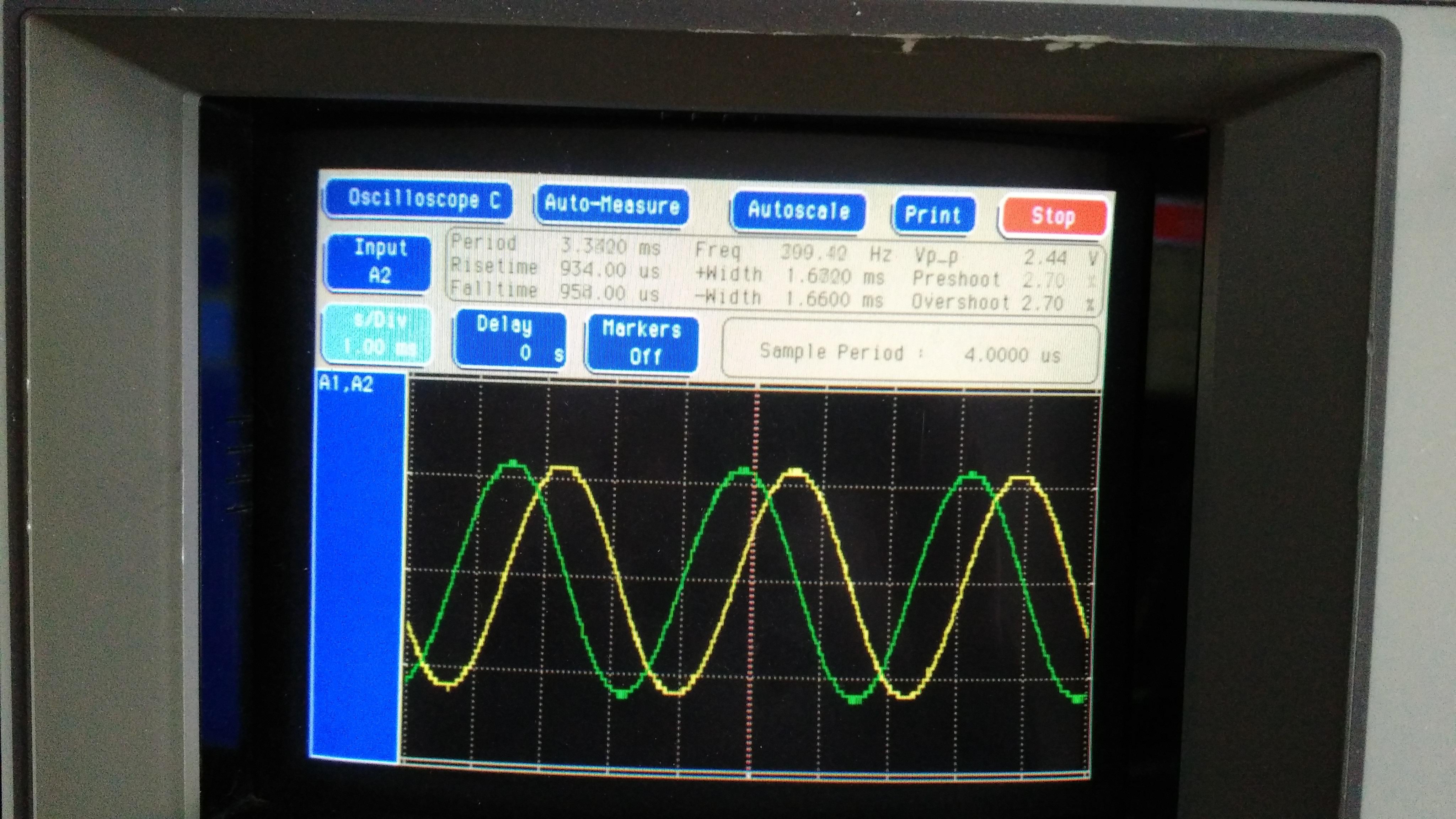
the other using 2.5mH crossing @300Hz:

-
So I rewired my crossover to use a 2.5mH inductor and precisely measured using my scope and also confirms with an AC voltmeter.
I re-simulated both the 1.25mH and the 2.5mH design.
The results are not surprising:
Using the 2.5mH, the crossover point is lower.
Simulation shows 338Hz @ -4Db
Measurement shows 300Hz@ -4.8Db
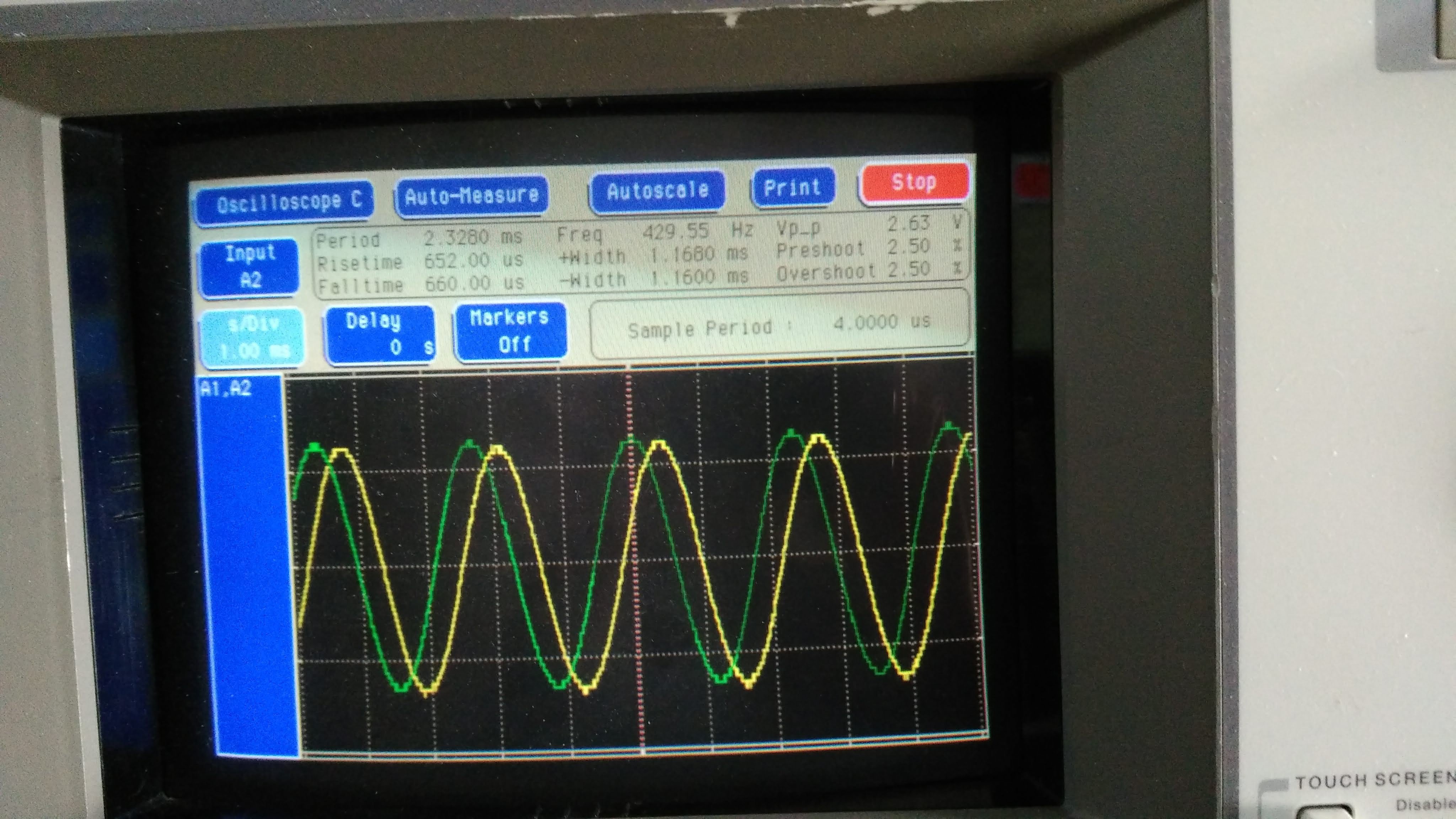
Using the 1.25mH, the crossover point is higher.
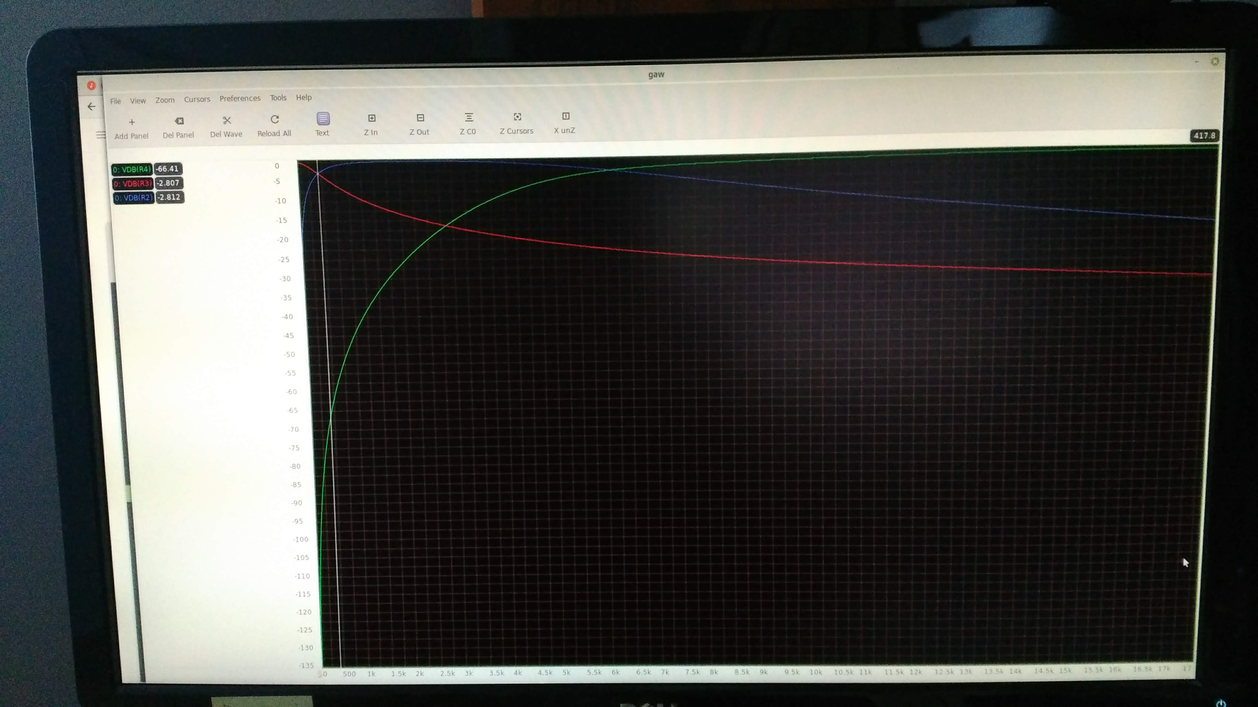
Simulation shows 417Hz @ -2.8Db
Measurement shows 430Hz@ -2.8Db
It is clear that my crossover requires the 1.25mH woofer inductance.
Joined are two pictures, showing equal low and mid levels and the measured period and frequency.
One channel on the woofer, the other on the mid, before attenuation.
Dan
-
in the next couple of days, I will revert one of my crossover to 2.5mH and measure the crossover point again.
Quite curious to see how this will compare to my simulation.
-
Mike, exactly as you describe.
I have a two channels oscilloscope. Channel one on the woofer, channel two connected to mid range before attenuator (Output of 300uH inductance). I then use "online tone generator" and find at which frequency the two channels reads the same peak to peak amplitude. This is the crossover frequency. I then measure the crossover input level. My measurement were 2.0Vpp (Woofer and midrange) with a 2.75Vpp input @ 430 Hz. 20Log(2.0/2.75) = -2.8Db very slightly off the -3.0Db (.727 vs .707)
Dan
-
I see Deang, L2 is about 2.5mH. The point is that part of this is in the voice coil.
Else, how can I explain my measured point is 430?
-
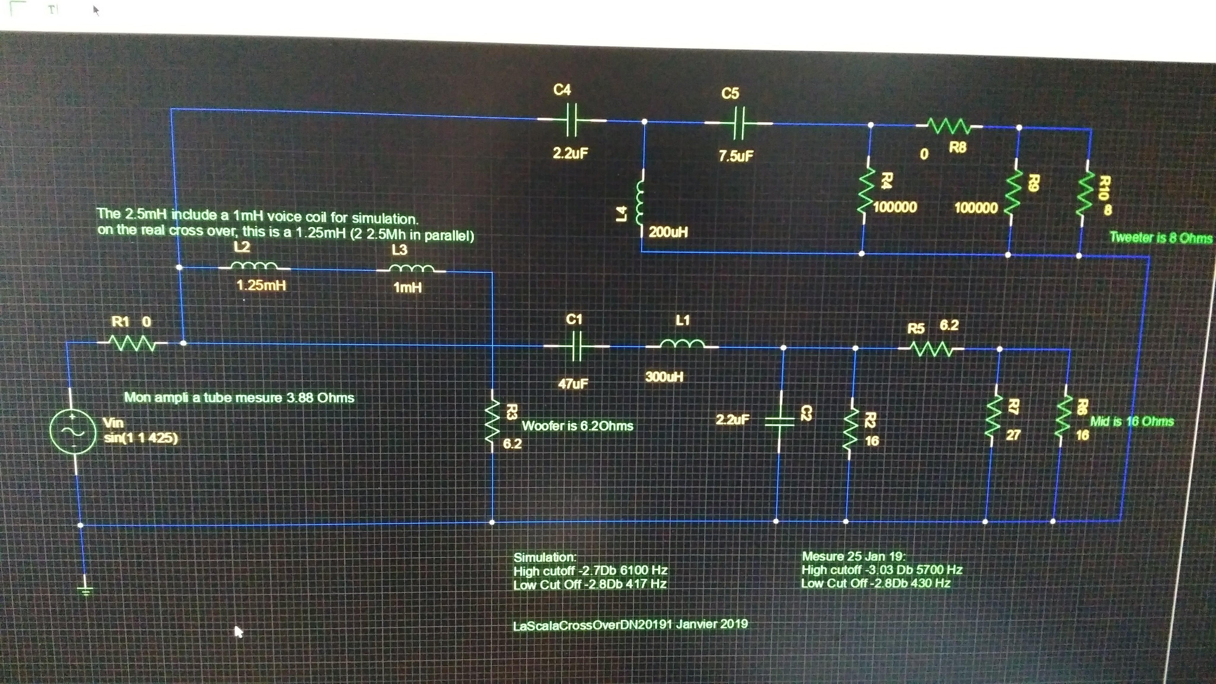
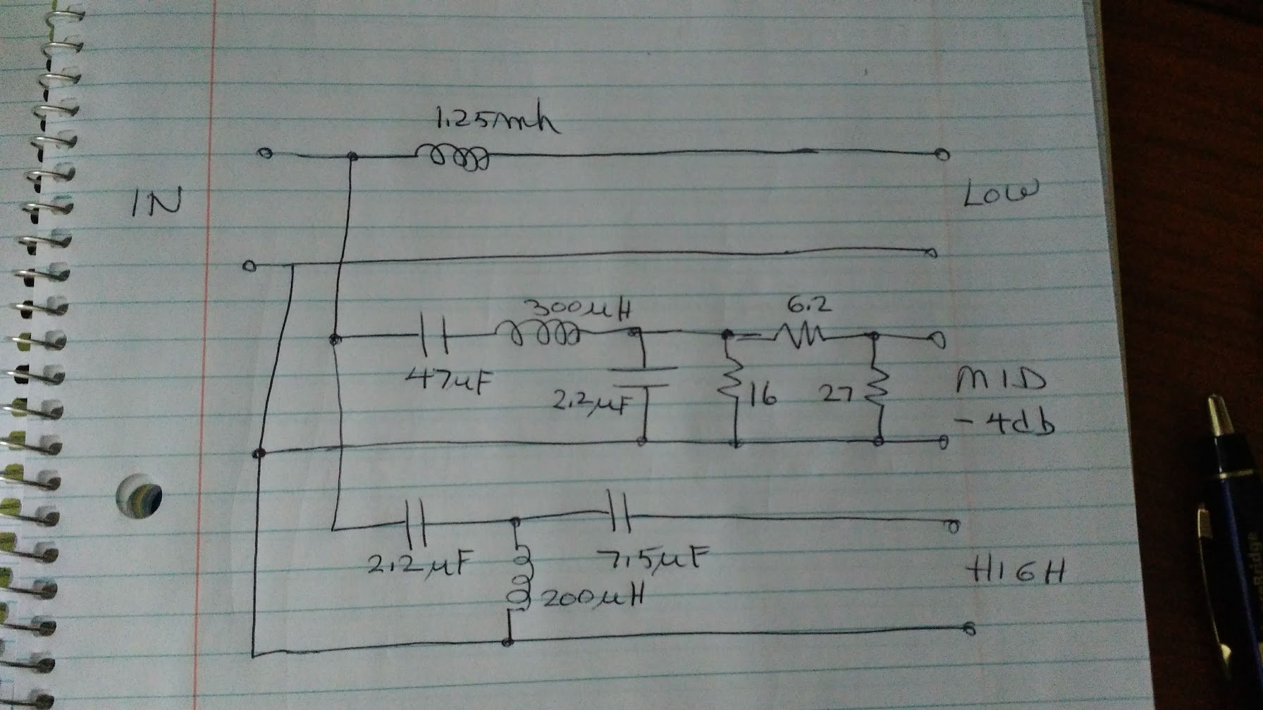
Here is the simulation schematic:
-
My spice simulation models the woofer as a 6.2 Ohms in series with a 1mH voice coil inductance. Adding my 1.25mH (Essentially two 2.5mH in parallel taken from the AL type crossover) brings the total to 2.25mH for my simulation. The resulting crossover is simulated at 417 Hz. Now, when I look at the actual electrical response of the crossover, I measure 430 Hz which matches quite well the simulation. Increasing the inductance lowers the crossover point in fact. Which crossover frequency is optimum from your point of vue?
-
Thanks for the answers,
yes I was referring to -4 DB, and it is quite a bit more lively than -6DB.
The more I listen to it, the more I prefer -4.
Oh i see Deang, you lined-up the center of the cores. i thought that been 90 degrees apart was sufficient at these low frequencies.
-
Now that the autoformer shock is (almost) passed, what is your opinion concerning the attenuation level?
-
Here is the spice simulation : It shows crossovers at 417 Hz and 6100 Hz.
Measurement were 430 Hz and 5700, Hz close enough.
-
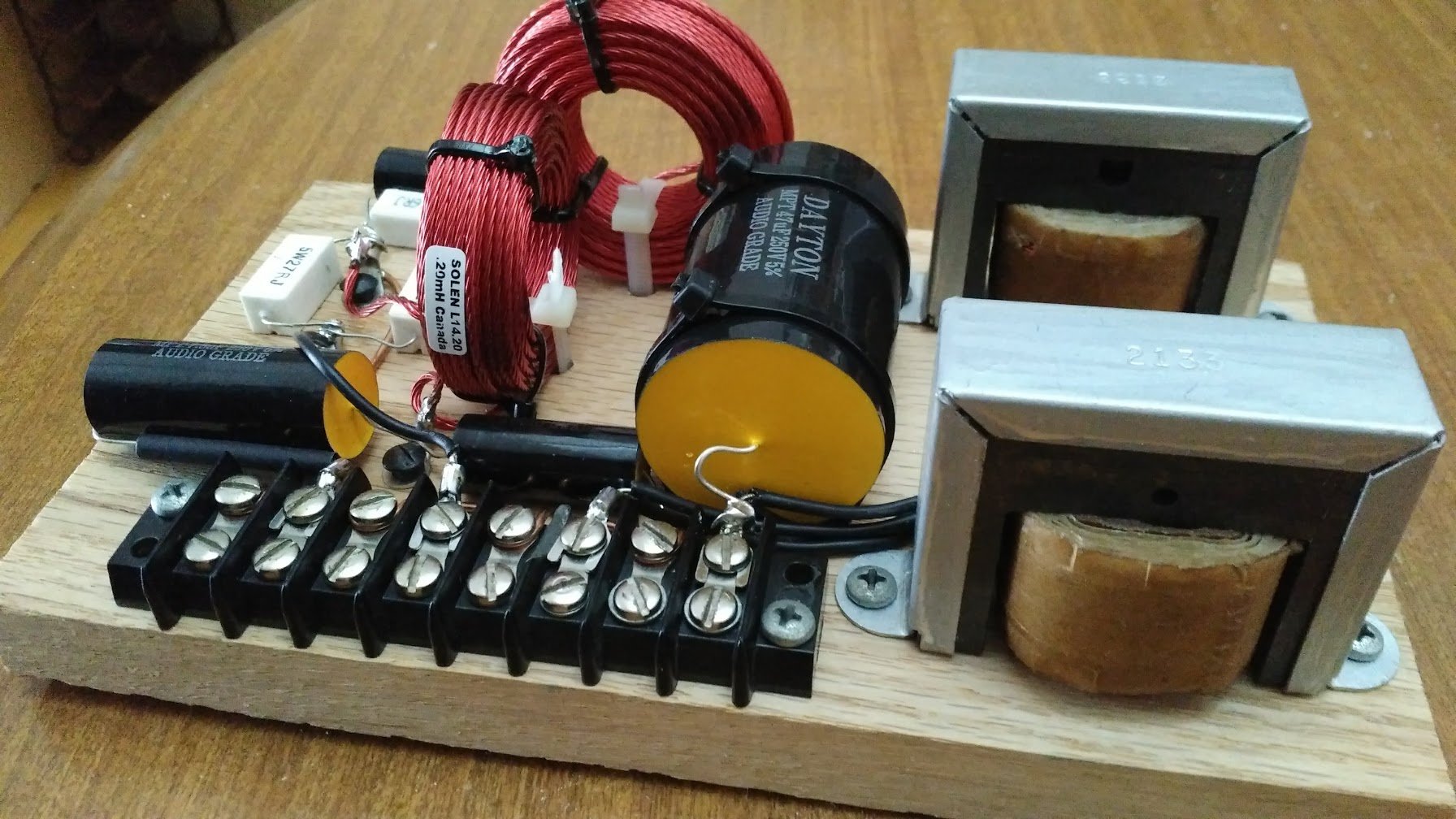
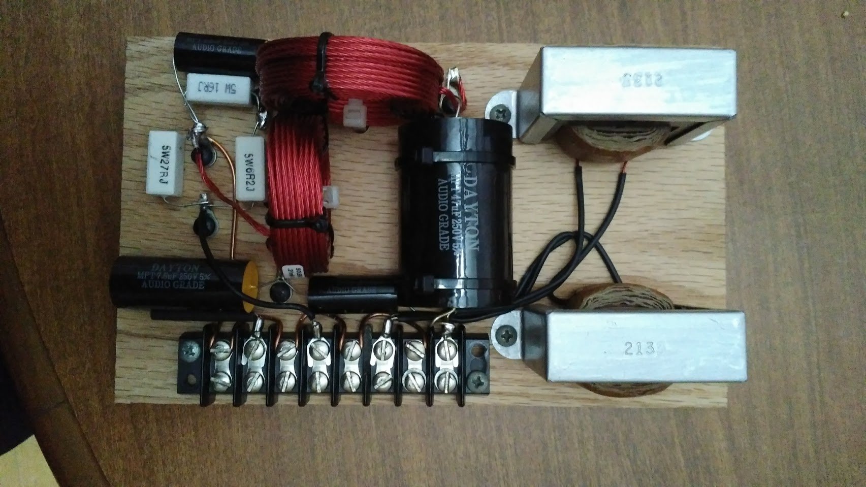
Claude, here it is, nothing very exotic except for the lack of the autoformers :-)
This is a slightly modified ALK universal. I measured the low crossover at 430 and the high at 5700 Hz,
Considering the mid driver fall as a rock at 6000, crossing a bit lower is a plus imho.
What is your preference for the mid attenuation in term of DBs?
-
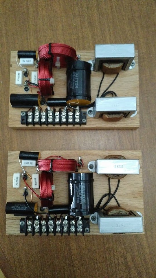
Finally, after a year with my 1988 LaScala, I replaced the AL type crossovers with a constant impedance set.
I took good care to simulate and then measure the results and i am now an happy camper :-)
I decided that a fix L Pad will be my preferred way to attenuate the mid range.
The original attenuation was 6 DB, but in order to make them more lively, I opted for a 4 DB pad.
What are your preferred attenuation?
Dan
-
1
-
-
My guess is that since the 300B heater current is quite high, there will be residual AC that can be cancelled out using the pot.
Dan
-
Thanks for your nice words, I also appreciate DIY very much for everything.
I must admit I am a bit perfectionist for the top look of my built, including the screws.
For the bottom, I do my best, but often modifications just ruin the perfect looks.
I was inspired by your previous post, and connected my 807 in triode mode.
I mapped the load from my existing transformer over the plate voltage/current graph in triode mode.
It provides a very good operating point.
I computed 1.8 Triode watts per tube, giving me a total of about say 3.5 Watts.
Since i use autopolarization (Current source on the cathode), this retains the DC operating point at 300Volts/60ma per tube.
At 18 Watts plate dissipation, this runs at 70% of the CCS spec at 25 Watts.
Conservative.
Wow I am impressed how much volumes I can get from the LaSaclas!!!!
What a punch on the basses.
I'm listening at Leonard Cohen right now.
I feel these 3.5 watts are solid as an hammer.
This comparison makes sense. What is preferable....15 watts but high output impedance, or 3.5 watts lower output impedance?
A big rubber hammer or a smaller steel one? :-)
It is possible to get the pentode amp to be low impedance, but it would requires 25 dB of feedback to equal the triode mode without feedback
i am not an audiophile (no golden hear anymore at 58 yrs old), but I really feel the refinement and details.
I will measure the output impedance for comparison.
Dan
-
Thanks for that.
I admire people doing such a clean job.
Mine is ok, but this one so good looking.
I noticed he is using global feedback.
My design uses schade feedback (Plate to grid 1)
I also use the 15 Watts GXSE Edcor transfo, 2.5k:8 in my case since I use two tubes in parallel.
I think the CXSE is a bit an overkill for my application.
The GXSE can go down to 40 Hz @1dBu which is perfect match to LaScala .
-
I looked-up the spec of your amp.
It is pentode based push-pull, ultra linear,
They also state less than 5 db feedback.
I dont know if this is in addition to the ultralinear, which is a kind of feedback in itself.
The best is to take some measurement before doing anything.
it looks like a quality instrument, and i would be surprise if the designers didn't control its output impedance (which is not the load impedance (4 or 8 Ohms).)
EL34 tube options for more bass/tonal richness
in Talkin' Tubes
Posted
I suspect the output transformer is more probably the cause instead of the tube itself.
Not enough primary inductance will cut into the bass.