iCeOL8TR
-
Posts
1 -
Joined
-
Last visited
iCeOL8TR's Achievements
Newbie (1/9)
0
Reputation
-
Bad power supply or amp? Klipsch R112SW
iCeOL8TR replied to Fala7er's topic in Technical/Restorations
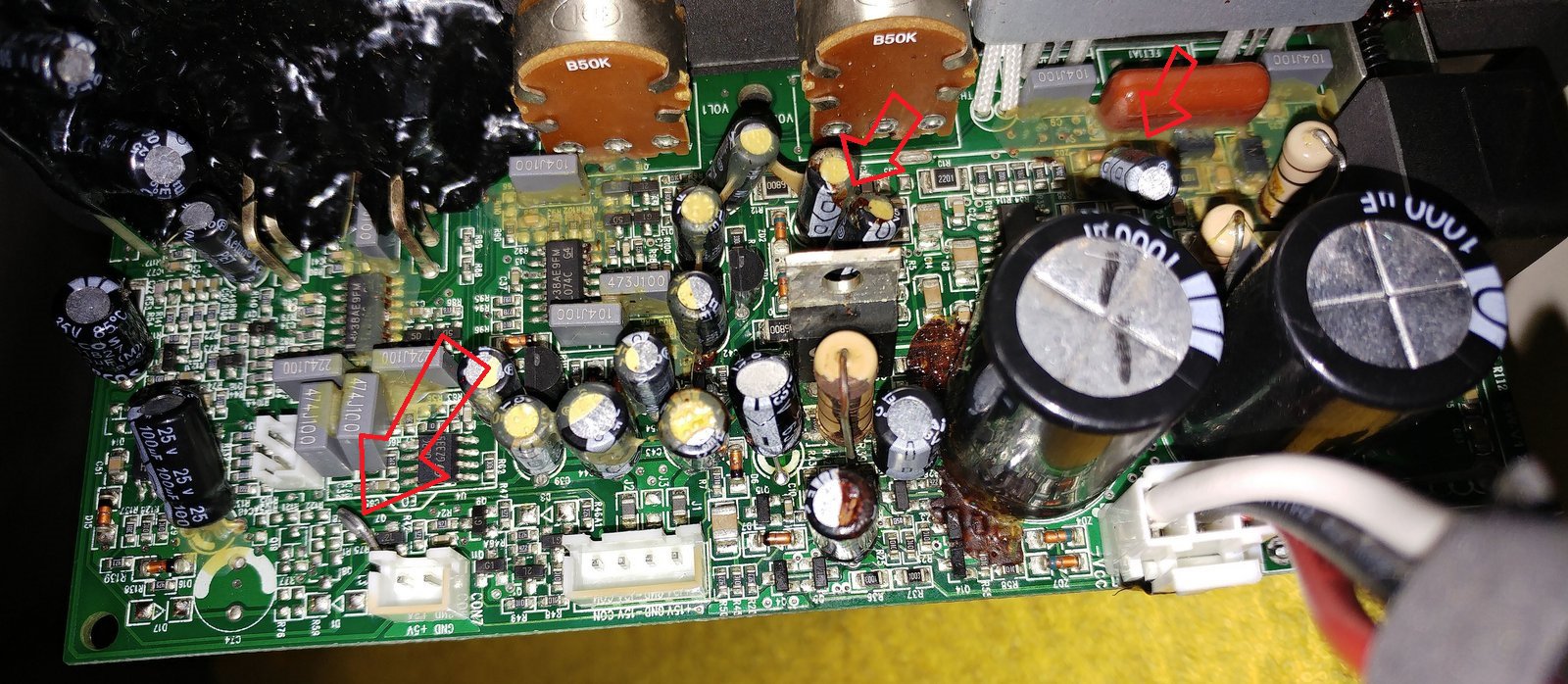
What is the value of the resistor? About to do this myself mine just started going out. Runs for like 10 mins then emits no sound blue light doesnt go out tho. Less burning on mine. I dont think its electrolyte leakage its just the glue is burned. The resistor must be putting out a lot of heat and its surrounded by components caps and a transistor. Wonder if the transistor is also damaged by the resistor and it has no heatsink. I'm thinking the resistor is the major culprit but everything else will have to be replaced with this fix. Maybe a large wirewound resistor would work(might make the amp/sound slower tho). Also certain caps are better with audio than others but not sure about that with this amp board looks like TL074C Ti(Motorola absorbed) opamps. Anyone know the value of the resistor? Not sure if the top band is a glued on resistor cap or that actually is a color value band..... Still looks like some fairly easy soldering... like repairing old motherboards.... Its odd cause there are no 2 different brown bands in the resistor band color codes theres only red and brown. Yet my resistor looks like a cap boundary/chocolate band a red band and then a lighter shade brown band which would then give 820 Ohm and I assume 1W power dissipation(replaced with a Kiwame 820 Ohm 5w been working good for a year) based on size comparisons on google images with a 5% tolerance gold band at the end, but if that is merely a cap glue seal and not an actual chocolate band then it would be a 20 Ohm resistor...... very confusing. It does appear tho that wirewound resistors are a step up in power dissipation(I see some 20W) and size both allowing higher power handling and less concentrated heat dissipaiton due to its larger size thus causing its peak temp to be less and thus less able to burn surrounding components. May slow down the sound tho, and I need to find somewhere to glue and secure it. Also I assume that is also you on the iFixit Page(https://www.ifixit.com/Answers/View/489741/Subwoofer+bad+power+suppply+or+amp) as your posts and situation are so similar(along with exact same glue burn residue patterns) I noticed a difference between my amp board and yours(attachment below) It seems your board has some metal lead hack jumper soldered onto your board to bypass something or some cheap fix by the manufacturer(did you add this? what does it accomplish?). Stood out when comparing your board and mine seems to go bond from one smt resistor to some r75 pad or thru hole for some purpose or another. Also notice this burning of the glue on the capacitors north of the transistor this indicates it is getting hot as well this is more evident on mine as there is a string of glue from the resistor to the transistor that is burned on both ends but not in the middle. Likely the transistor also needs to be replaced as its also overheating and likely a heatsink installed for future protection. Notice how Burson always puts a heatsink its not like the manfacturer designed that metal plate on the component and screw hole for nothing..... https://6moons.com/audioreviews/burson3/burson_2.html Also just to note this small cap north of the 2 large caps has no thru hole to solder its leads so instead they created 2 large solder balls on pads and then sunk the capacitor leads into these large solder balls and then covered the whole thing with the yellow glue. This is not proper electronic design or practice.... You would think with the number of these things they have made and sold over the years they would have had a board revision to fix this by now..........