ngen33r
-
Posts
166 -
Joined
-
Last visited
Content Type
Forums
Events
Gallery
Everything posted by ngen33r
-
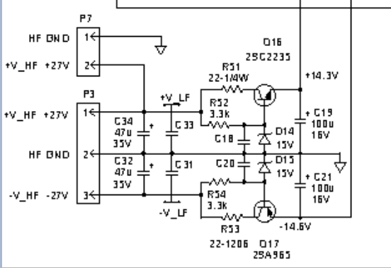
I have not made any test fixtures. I keep a spare power supply that is known good and use that as a test rig. You can always socket the components for testing then remove the sockets for final install. I have attached my version of the schematic. 660045-1.sch
-
The BIAS could be way off or the volume is too high. Testing should always happen with the volume at 5% or less. If the outputs were replaced the pots will need to be adjusted. I plan to cover this in a future video. The unmarked DIAC is a DB6 and can be sourced from NTE.
-
This is looking great. I have done this in the past, but I never had the time to fully invest into making the schematics. Are you using Eagle or Kicad? I can just upload the schematic file for you.
-
An 8A fuse will NOT blow with the bulb in series. Something is wrong in your setup. The most current that can be sourced would be ~1A before the bulb goes full on and clamps the current. I replace the via with a thru hole repair kit. They are VERY expensive for what they are but needed IMO for a professional repair.
-
I DO NOT LIKE PROVIDING THESE FILES 1. BECAUSE PEOPLE THEN PESTER ME AND ASK FOR THEM 2. BECAUSE I PUT A TON OF TIME INTO CROSS REFERENCING THE DESIGNS AND PARTS AND ALL THIS INFO CAN BE GOOGLED THIS IS A SIMILAR POWER SUPPLY FROM BASH USED IN AN INFINITY THIS IS FOR REFERENCE ONLY AGAIN THIS IS FOR REFERENCE ONLY 500W BASH.pdf
-
RECAP & repair the control board. No schematics are known to exist for these.
-
DO NOT BUY PARTS FROM AMAZON, DON'T DO IT! https://www.digikey.com/en/products/detail/on-semiconductor/2N4401BU/1417 https://www.digikey.com/en/products/detail/epcos-tdk-electronics/B57211P0100M301/2781797 PDC parts are listed on the schematic I made and posted. Rebuild requires replacing what is bad and what PDC you have. There are 2 different versions with different parts. FETS are IRF730/740 depending on the amp you have Everything is available on DigiKey or Mouser, or any reputable parts supplier.
-
-
R-110SW / R-112SW / R-115SW Repair Blog
ngen33r replied to ngen33r's topic in Technical/Restorations

-
R-110SW / R-112SW / R-115SW Repair Blog
ngen33r replied to ngen33r's topic in Technical/Restorations
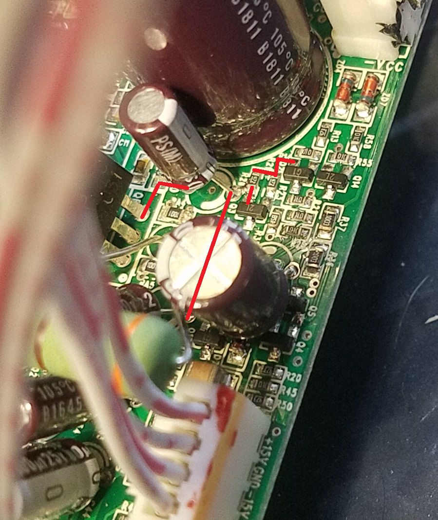
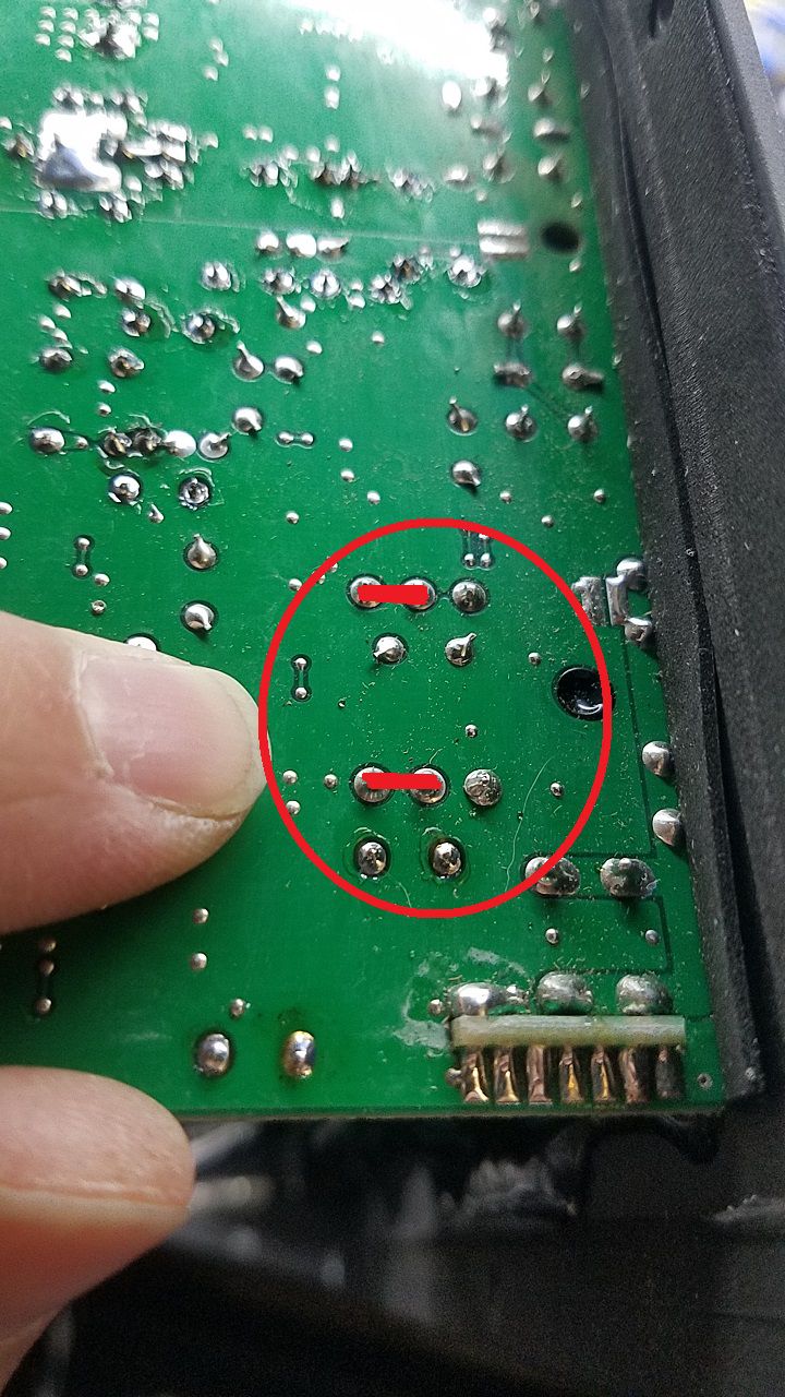
Cut off the legs and solder jumper wires in the position you want
-
R-110SW / R-112SW / R-115SW Repair Blog
ngen33r replied to ngen33r's topic in Technical/Restorations
SW-10 REPAIRS SHOULD GO WITH SUB-10 AND SUB-12 I WILL REVISE THAT TITLE IF I CAN EDIT IT. PLEASE MOVE THIS POST IN THERE. THANK YOU -
R-110SW / R-112SW / R-115SW Repair Blog
ngen33r replied to ngen33r's topic in Technical/Restorations
-
Here is that part:
-
RW-10 - RW-10D / RW-12 - RW-12D REPAIR BLOG
ngen33r replied to ngen33r's topic in Technical/Restorations
-
The 104 is an Inrush Limiter https://www.datasheet4u.com/datasheet-pdf/Voltts/SCK-104/pdf.php?id=675090 https://www.digikey.com/en/products/detail/epcos-tdk-electronics/B57211P0100M301/2781797 If that is blown 99.999% of the time your fets are toast too as well as some other passives.
-
-
-
10V is high. 8V is normal. Something else is wrong.
-
R-110SW / R-112SW / R-115SW Repair Blog
ngen33r replied to ngen33r's topic in Technical/Restorations
No drawings or schematics are known to exist to the public at this time. -
You need to de-solder them and solder new ones in. If those are blown, you will have more bad things than that. https://datasheetspdf.com/pdf/685354/THINKING/SCK-048/1
-
Here is an RT-10 repair and what I learned.
-
These amps are always fixable even if almost destroyed.
-
R-110SW / R-112SW / R-115SW Repair Blog
ngen33r replied to ngen33r's topic in Technical/Restorations
-
And so it begins. I have started my video blogs and will continue to support the repair community with detailed videos of how I do a repair.
-
RSW's start with the caps and start tracing the circuits. These are not easy.