ngen33r
-
Posts
166 -
Joined
-
Last visited
Content Type
Forums
Events
Gallery
Everything posted by ngen33r
-
Pin 1 is not connected. If I remember correctly it is a shutdown pin to turn the entire supply off.
-
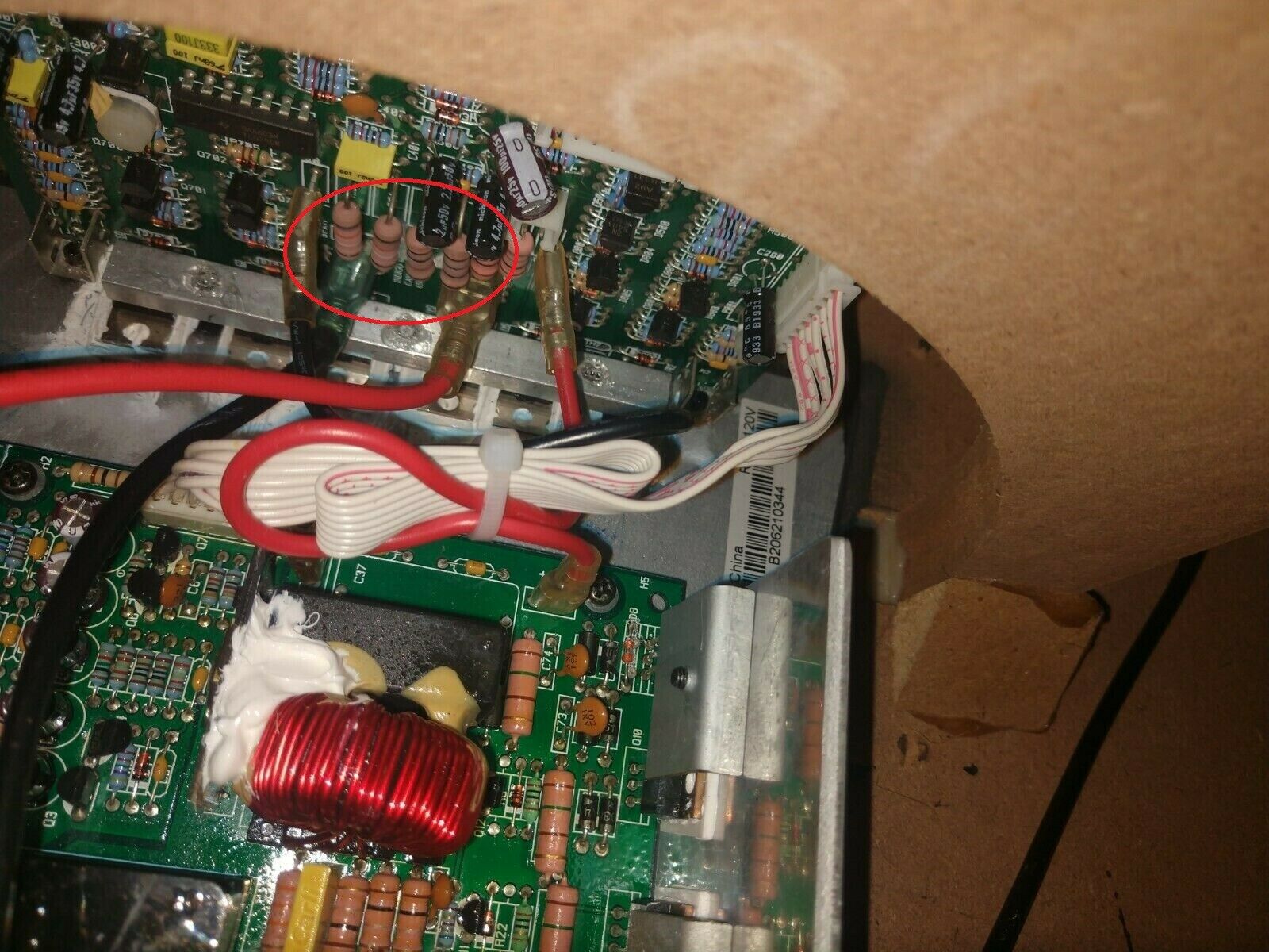
Tommy, That is perfect. I am going to call those 330ohm 5% (Orange Orange Brown Gold) 2W. Since these seem to get rather hot and burn. I will use 3W flameproof replacements. Such an odd failure, but then again people leave these things on 24/7 so I am not suprized.
-
Tommy, I need the big pink ones that are on the board that is standing up on the triangular shaped plate. If you want to send it out for science and the good of the repair community, PM me.

-
Can anyone get me a closeup of the resistors on the vertical amp board. R102 R103 R104 R105. I have a board with these failed and they are burnt to a crisp and I can't identify them.
-
MMBZ5243 13V ZENER
-
RW-10 - RW-10D / RW-12 - RW-12D REPAIR BLOG
ngen33r replied to ngen33r's topic in Technical/Restorations
The DIAC is usually the issue if the PDC is not working. -
IMO that is a fire waiting to happen. The VIAS should be replaced and a proper repair done to that board. Credit for getting it working, but I would not want that in my living room.
-
There is no parts list. TH3 is a DSP104 10ohm 4A inrush limiter.
-
Not showing, but C32 is 0.1uF 100V ceramic https://www.digikey.com/product-detail/en/kemet/C430C104K1R5TA7200/399-4503-1-ND/818360
-
That amp is the same as many KSW amps. Check out my KSW repair blog.
-
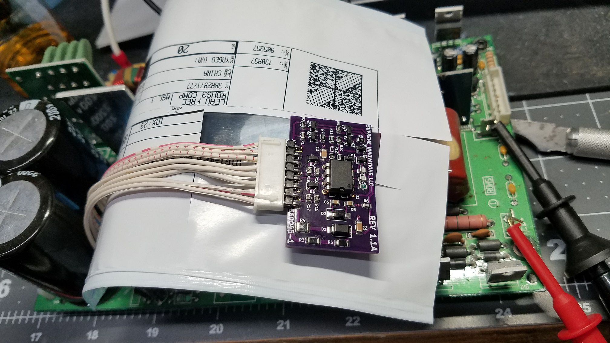
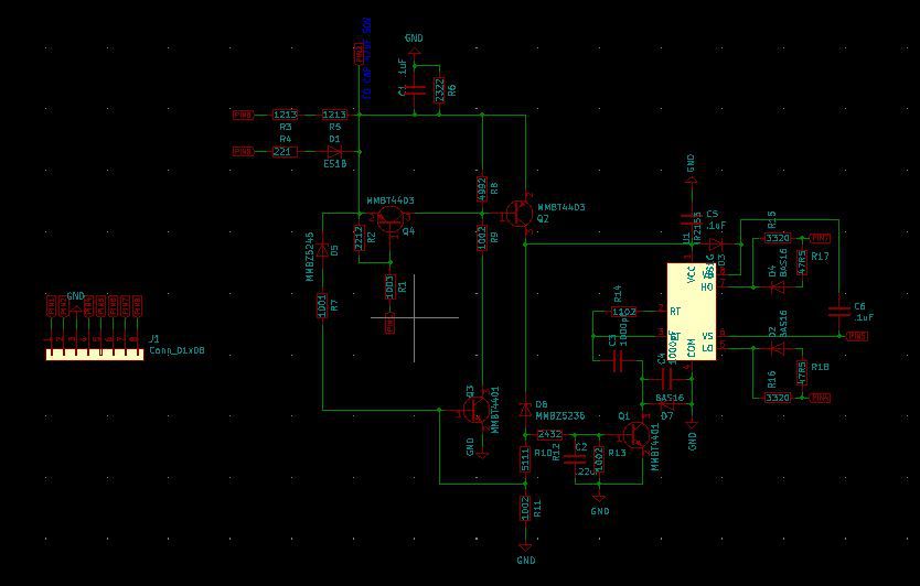
Finally got around to assembling one of these boards and testing. Worked great the first time so I will post the schematic for some of you. I am currently on summer break from repairs so my posts will be less frequent.
-
I cannot see the pictures, but I will look that up when I can.
-
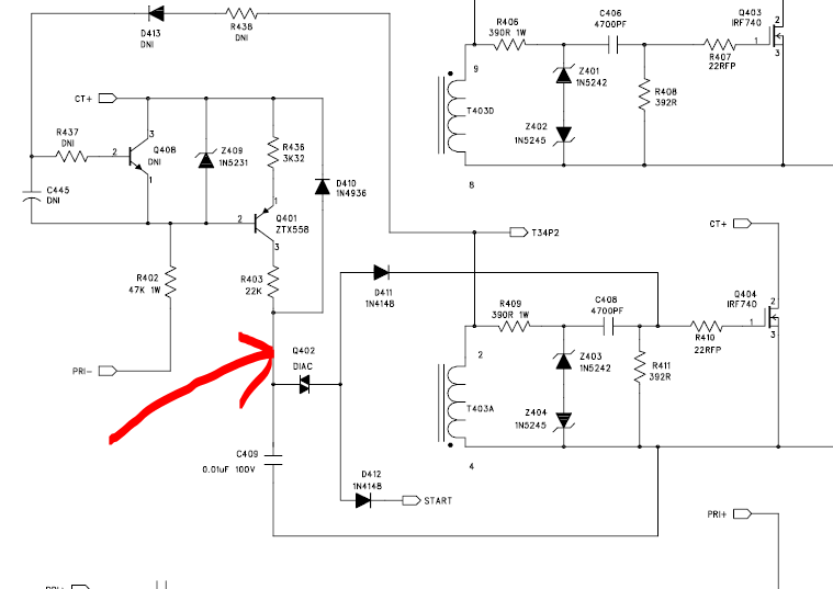
Well, I am officially stumped. I am working on a RSW-15 and I need some help. I cannot get the supply to start. I triple checked all the components, replaced all the diodes and the supply wont start. The diac is good but I am only getting 45V to the diac and it needs 60V to start. Here is a snip from the schematic. Top of R403 I am getting 75V. Q401 tests good, but also was replaced. CT+ is at 170V. Both transformers measure the same inductance per winding so either both transformers failed the same way or I am missing something. This unit did have a meltdown of the big inductor as seen above. If I replace C409 with a .22uF cap the supply will start but not function properly. I'm stumped. The thing that sucks is the amp board is repaired and working as I tested it with another supply, but that supply was sent back to the owner. This guy is super cool and I want to get this going for him again. Anyone have a bad amp??? to start.
-
SUB-12 PLATE Y9103700738 This was a pretty typical repair. The glue cancer took this one out. Fets, NTC, PDC and caps.
-
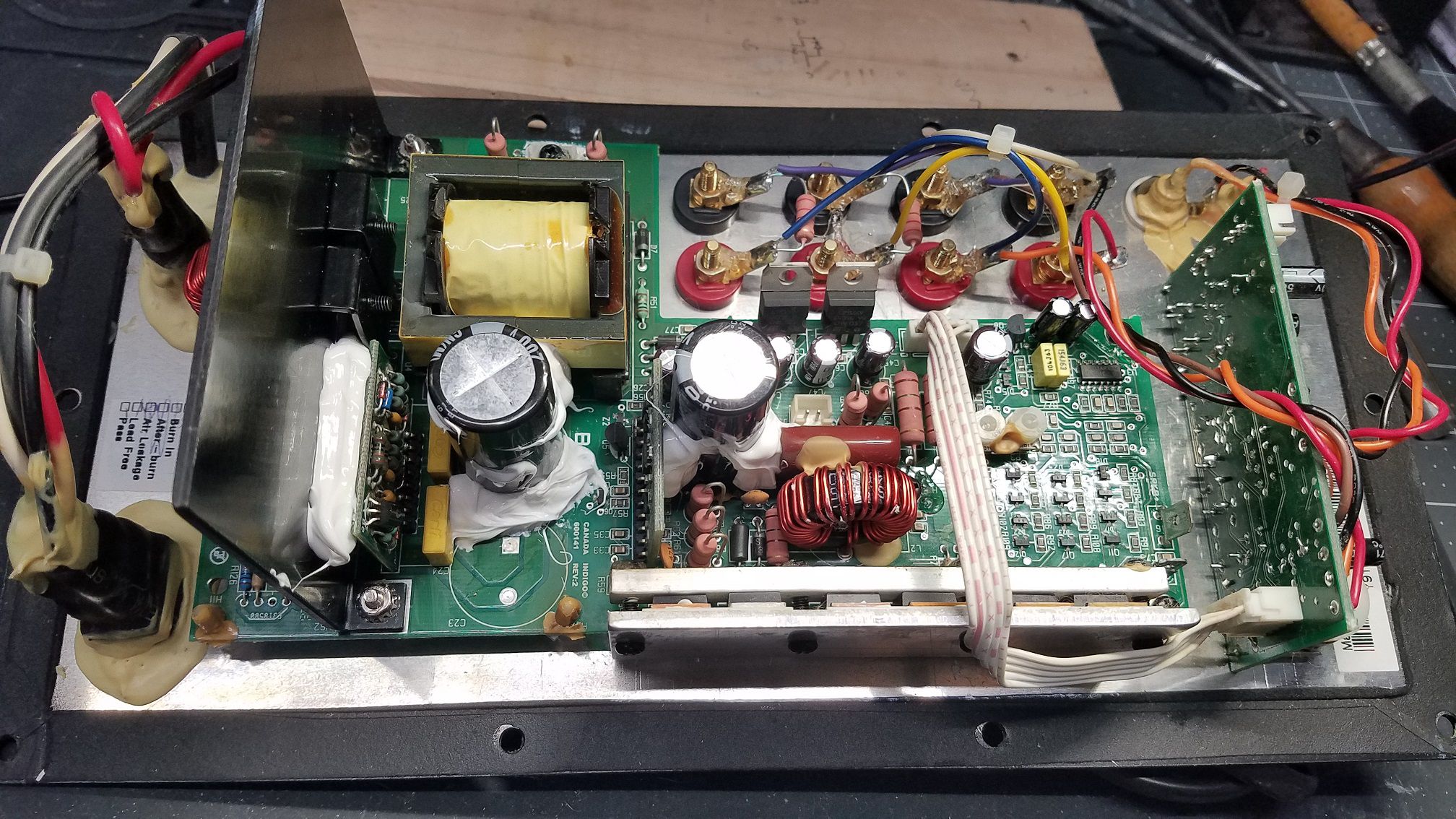
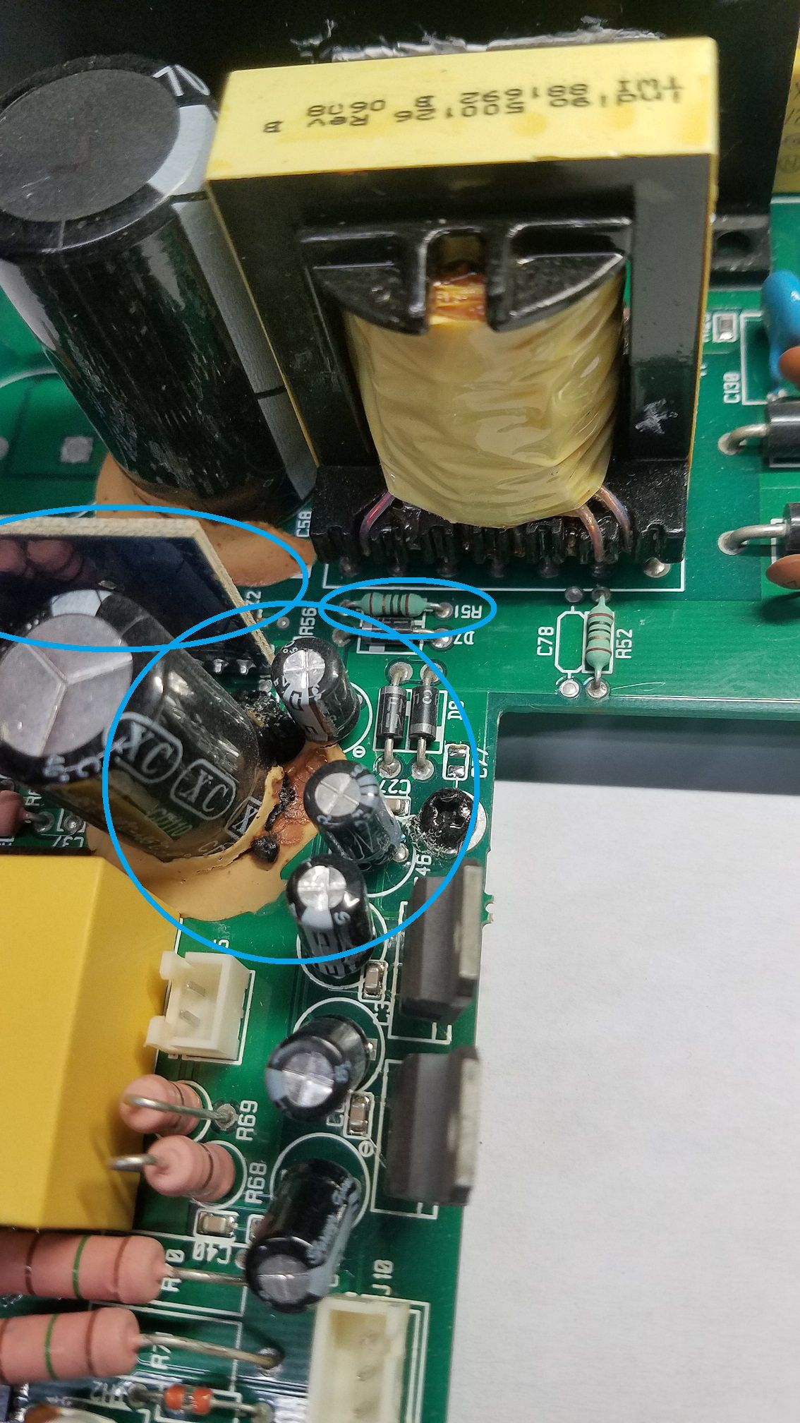
RPW-10 PLATE A506220506 FINALLY, something different. This failure was not one I have seen before. C31 appears to have prematurely evacuated and caused all sorts of issues. Z2 was toasted, Q5 evaporated and R51 failed. The BASH board was taken out as well with a blown diode, transistor and the IC. The IC's are a pain in the *** to replace because of the glue or epoxy used to try and hide the UC3842 chip. The board did have some damage to the copper plane under the cap, probably from the electrolyte. This is a fairly easy spot to repair. Best guess, Q5 failed and took out the bash board and caused Z2 to fail. R51 then failed from heat due to the current draw. When the bash board stops working the voltage on C31 goes over 100V, which it is only rated for and that would cause the leakage. Normal voltage is around 90V. This is why on later revisions this cap was upgraded to a 160V version. It is still OK to use a 100V cap here, as long as the amp is working properly. Go 160V if you want to play it safe. As usual, glue removal and Q5 upgrade with a full recap.
-
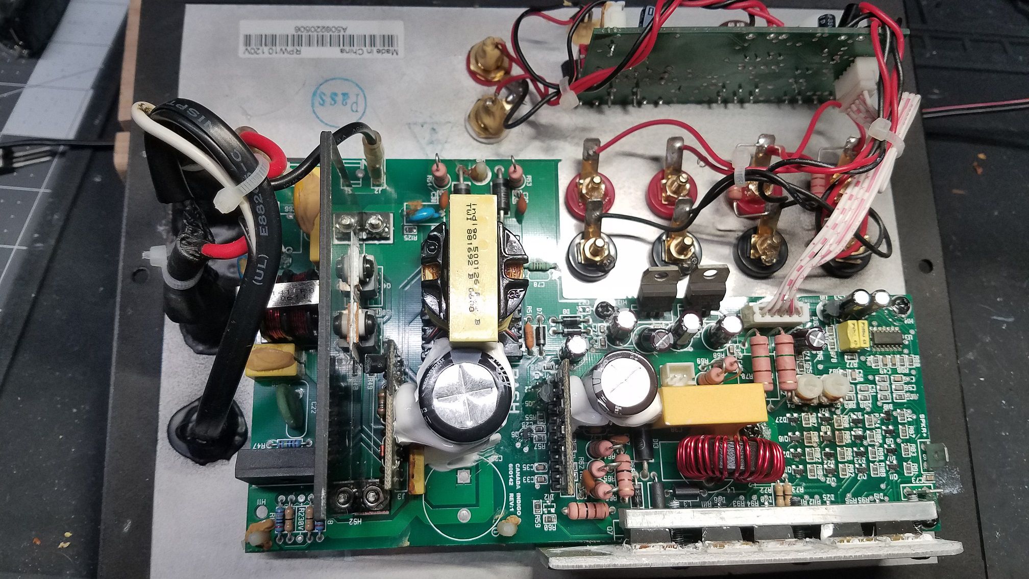
RPW-10 PLATE SI-00129 This plate is a trade in repair. I am trying to clean up my parts box that is overflowing, so I am going to start punching these out so I can get more organized. Typical repairs on this one. TH3 exploded, fets were shorted, PDC failed. Full recap and Q5 upgrade completes this one. The thru holes for the fets had damage from an attempted repair, so I had to freaking fix those. IF YOU DON'T HAVE A VACUUM DESOLDERING TOOL CUT THE DAMN LEADS AND SAVE THE THRU HOLES!!!!!!!!!!!!!!!!!
-
I have to say, nice repair. I would not have thought to go old school and do point to point. For personal use, why not as long as it works.
-
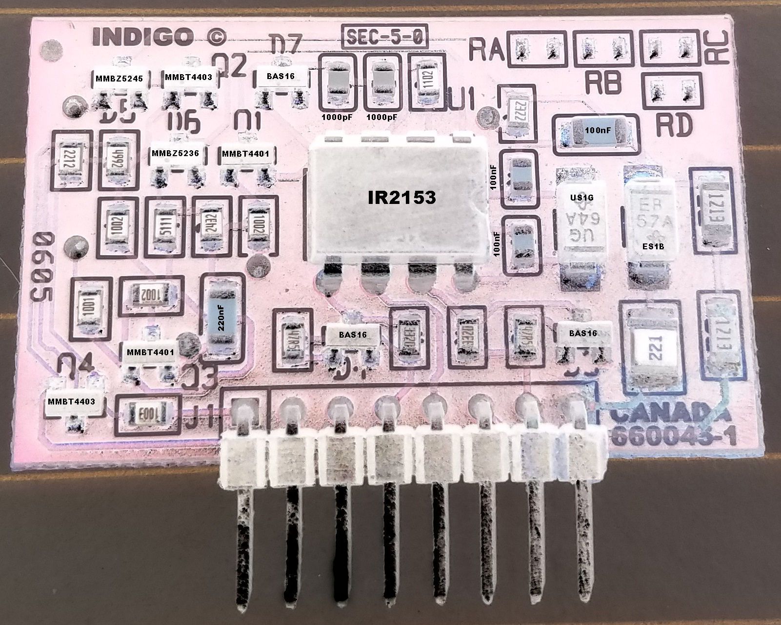
I have received some messages about the control board, so I will share this with everyone. This has all of the unmarked component values on the control board.
-
RW-10 - RW-10D / RW-12 - RW-12D REPAIR BLOG
ngen33r replied to ngen33r's topic in Technical/Restorations
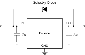
Thinking about this more, that might not be a zener. Typically a zener is not placed across an LDO like that I am guessing that is a protection diode. https://www.onsemi.com/pub/Collateral/MBR0540T1-D.PDF
-
I can try, but it will be like a blind man throwing darts.
-
I would recommend removing parts from board. Clean good, put tape on back of the board and fill hole with epoxy. I will send the pictures in a message. Failure of BASH board causes the resistors to burn like that and damage the board.
-
RW-10 - RW-10D / RW-12 - RW-12D REPAIR BLOG
ngen33r replied to ngen33r's topic in Technical/Restorations
The techs there have cross referenced me parts that were not correct and have caused hundreds in extra damage. I will never make that mistake again even if it was bad luck. Do some homework and use the available resources https://www.sphere.bc.ca/download/smd-codebook.pdf http://www.s-manuals.com/smd/b4 B4 BZX399C2V4 Phi I SOD323 2.4V 0.3W zener B4 SOD-123F BZT52H-C2V7 NXP Zener diode I would start with that. Keep in mind that I have never had to replace one of those diodes EVER!!! Putting 5V to the output leg of the VREG and ground to the plate should power on the LCD and confirm that diode to be good. -
I didn't know they made an RPW-10D. I know they made RW-10 and RW-12D subs. When I see that issue on them it typically requires a recap, replacing SMT diodes and the SMT VREG. About 60% of the time the digital volume IC is fried when the VREG goes. Those are not fun to solder in. If it is an RW series, please post in that blog. I want these threads to stay on topic.
-
That board is not worth fixing. I have several of those in my graveyard. Toss it and replace the amp. You would have to do epoxy board repairs, add new copper planes, rebuild the bash board, recap the entire board, replace the outputs and pots at a minimum. Scrap it and get a "good condition" broken amp that hasn't almost caught on fire.
-
Sounds like the amp needs a recap and possible some other service.