ngen33r
-
Posts
166 -
Joined
-
Last visited
Content Type
Forums
Events
Gallery
Everything posted by ngen33r
-
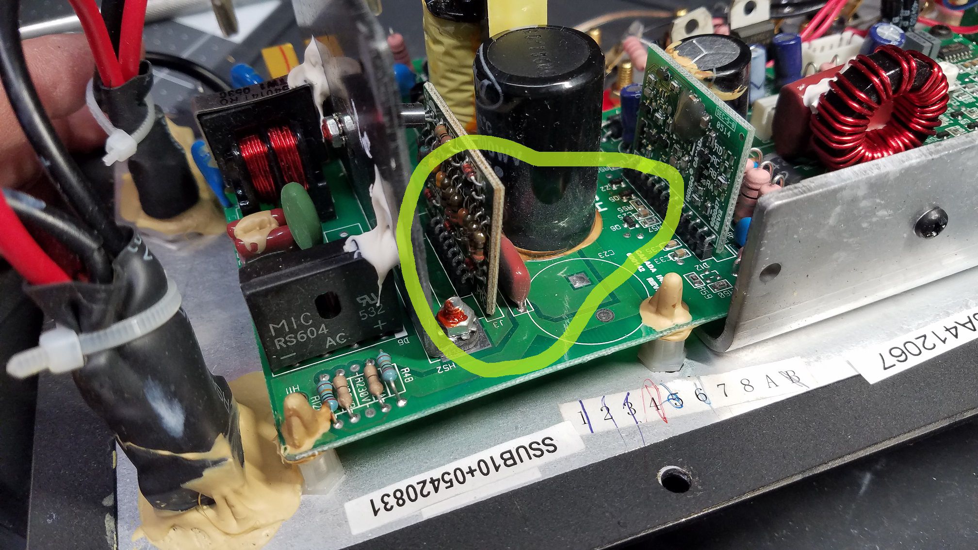
SYNERGY SUB-10 PLATE SERIAL 05420831 This one looks a little brown and crispy. The back of the red film capacitors also has some nice black magic smoke on it. Q5 is turning brown from overheating. This will need a full recap, removal of all the glue, Q5 and fets replaced and rebuild of the PDC board.

-
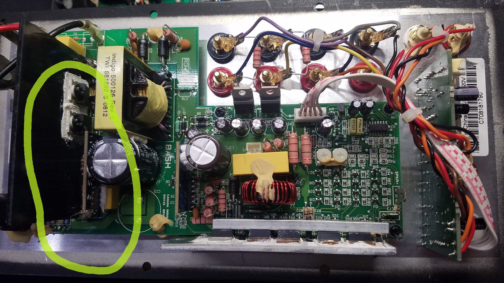
SYNERGY SUB-10 PLATE SERIAL C708181790 Another glue death. This version had the Q5 upgrade so just needed repair and recap. PDC Rebuilt Fets Replaced Full Recap
-
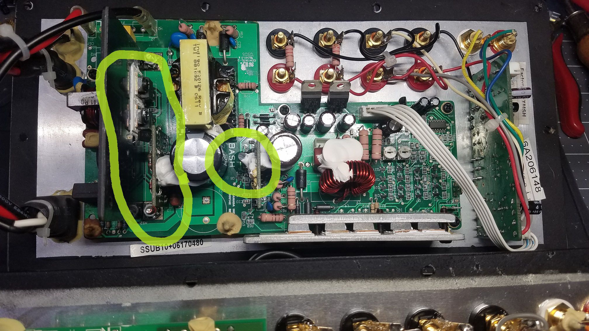
SYNERGY SUB-10 PLATE SERIAL 06170480 Another victim of the glue plague PDC Rebuilt Fets Replaced Q5 Upgraded to TO-92 Full Recap
-
R-110SW / R-112SW / R-115SW Repair Blog
ngen33r replied to ngen33r's topic in Technical/Restorations
-
R-110SW / R-112SW / R-115SW Repair Blog
ngen33r replied to ngen33r's topic in Technical/Restorations
R-112SW plate serial number LH150400882 Had some time tonight to complete another one of these. Repair and full recap. R39 had a meltdown and dried up a few caps and killed the PWM controller power supply. I gooped it pretty good with silicone to dampen the stress on the solder joints so I can let the hot parts breathe a little.
-
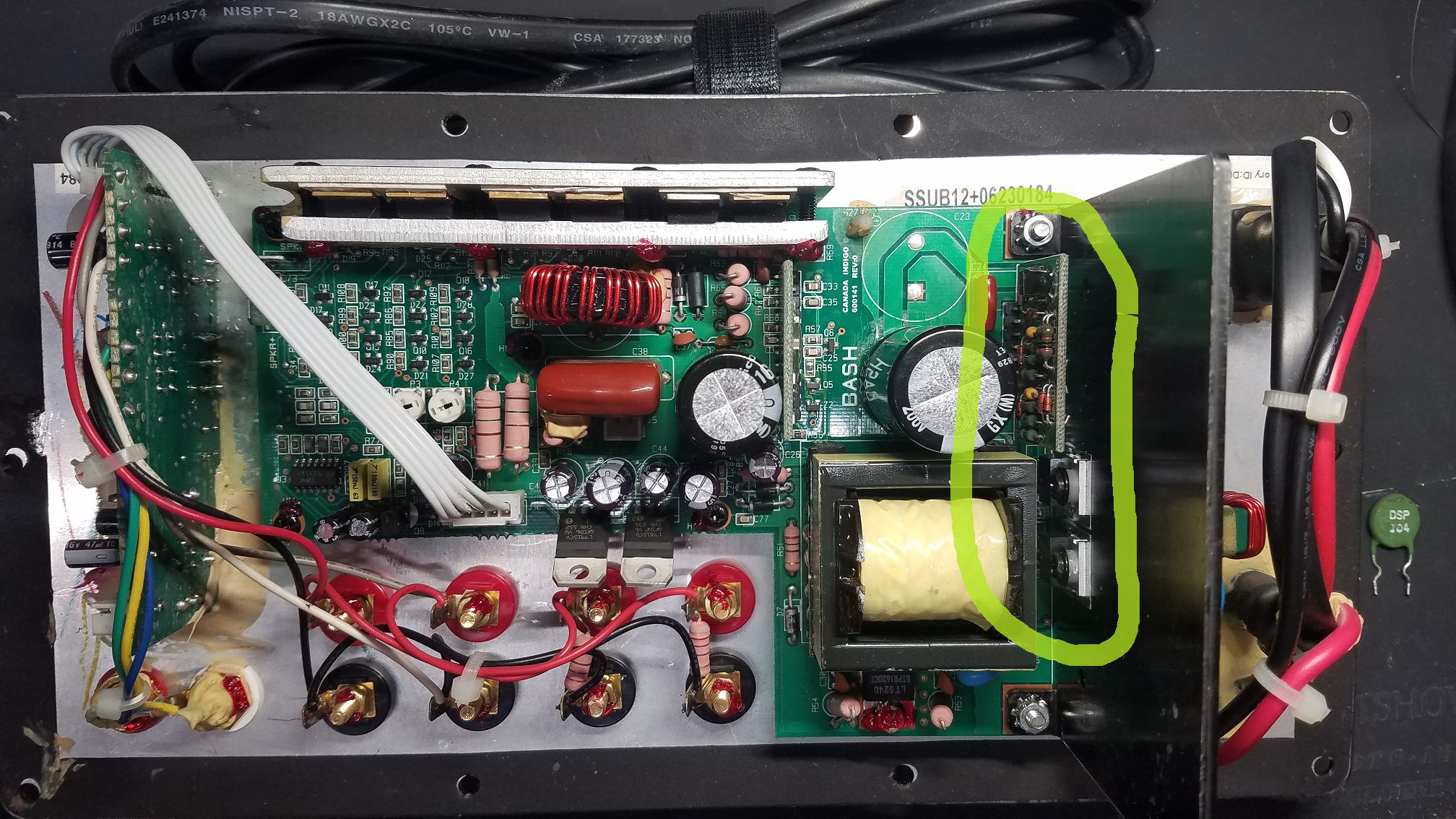
SYNERGY SUB-12 PLATE SERIAL 06230184 This amp was blowing fuses. The PDC control board failed and took out the mosfets. I had to clean and rebuild the PDC, replace the fets, replace Q5 and TH3. TH3 is almost always bad when fuses are blowing. After the board was working, a full recap was done on the amp.The active crossover was especially fun due to all the damn glue used.
-
R-110SW / R-112SW / R-115SW Repair Blog
ngen33r replied to ngen33r's topic in Technical/Restorations
This does not at all pertain to this thread and I wish the mods would delete this post. Please send me a PM. It is against forum rules to openly discuss this. I have also had a lot of success on eBay doing repairs. https://www.ebay.com/itm/252834002186 -
R-110SW / R-112SW / R-115SW Repair Blog
ngen33r replied to ngen33r's topic in Technical/Restorations
That information can only be obtained from a schematic. I will have to have a look if Infinity used this same amp. They almost always have service manuals that can be found. -
R-110SW / R-112SW / R-115SW Repair Blog
ngen33r replied to ngen33r's topic in Technical/Restorations
The resistor is 820 ohm 3W. It almost always kills the transistor and the surface mount resistors and a couple diodes need to be replaced. The whole board also will need to be recapped after that failure. -
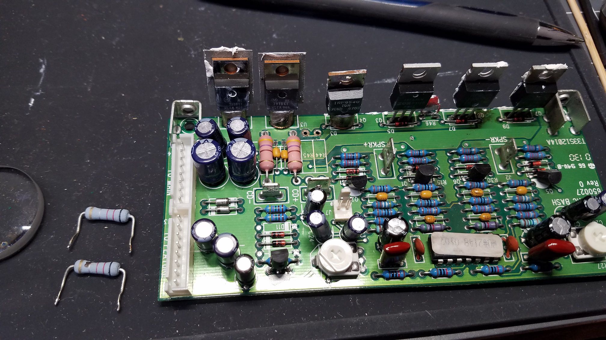
RSW-10 PLATE SERIAL ??? First up we have a RSW-10 and this one already is a challenge, because someone was already inside and changed parts. I have 2 burnt resistors that look to be replaced and might not be the correct value. R44 and R45 on the amp board. I also see that 3 fets were replaced. I need to confirm that Q7 should be an IRF640 and not a IRF530. The amp board is 650027 and it appears that SVS used this same amp in the 20-39PC. Oddly enough the Infinity IL60 uses the same amp board so I should be able to get a good parts reference from that. More to come tomorrow, I'm tired. Update:1/18/20 I replaced the fets and have the resistors on order. The resistors are .1ohm 2W Wire Wound ADJUST BIAS PROCEDURE (Mandatory when any output MOSFET transistors Q3,4,7,8 are replaced) 1. Amplifier should be unplugged and OFF. 2. Remove Amp assembly from cabinet; remove rear plastic cover if present. All wires exiting the cover can remain connected unless they will prevent you from removing the amplifier or accessing potentiometers on the Linear board PCB in the following steps. 3. Locate the Linear board assembly (PCB with the output transistors) 4. Adjust R11 and R27 fully Counter Clockwise. See diagram below. 5. Apply 120 VAC power to unit, Turn power switch ON. 6. Verify LED illuminates on the front gain control dial unless you have disconnected the plug. 7. Connect voltmeter set to DC millivolt range to twin pins on terminal J7, on Linear board 8. Verify initial voltage is less then 0.1 mV. 9. Adjust R11 Clockwise until voltmeter reads 0.3 mV + the initial current from step #8. 10. Adjust R27 Clockwise until voltmeter now reads 0.6 mV + the initial current from step #8. 11. Turn amplifier OFF. Disconnect AC power to unit. 12. Remove voltmeter from terminal J7. 13. Replace cover (if present), wires if disconnected, and replace amplifier back into cabinet.
-
Hello All I have been repairing Klipsch subwoofer amps for about 15 years as a hobby. I have decided to start blogging my repairs and eventually do videos of each one. This thread is intended to be a blog and a resource for information. I will try to answer repair questions as best I can. Comments and tips are also welcome, If you do not have the experience or the tools, PLEASE do not attempt any of these repairs. You will only end up damaging the board and it will end up costing more for a tech to repair the damage. If you do not have a high quality vacuum desoldering station (Hakko or Weller) and a current limited mains supply, you should not be working on these amps. These subwoofers do not have any user serviceable parts inside. If you open up the sub or attempt any repair you see in this thread, you are doing so at your own risk!!! Wayne
-
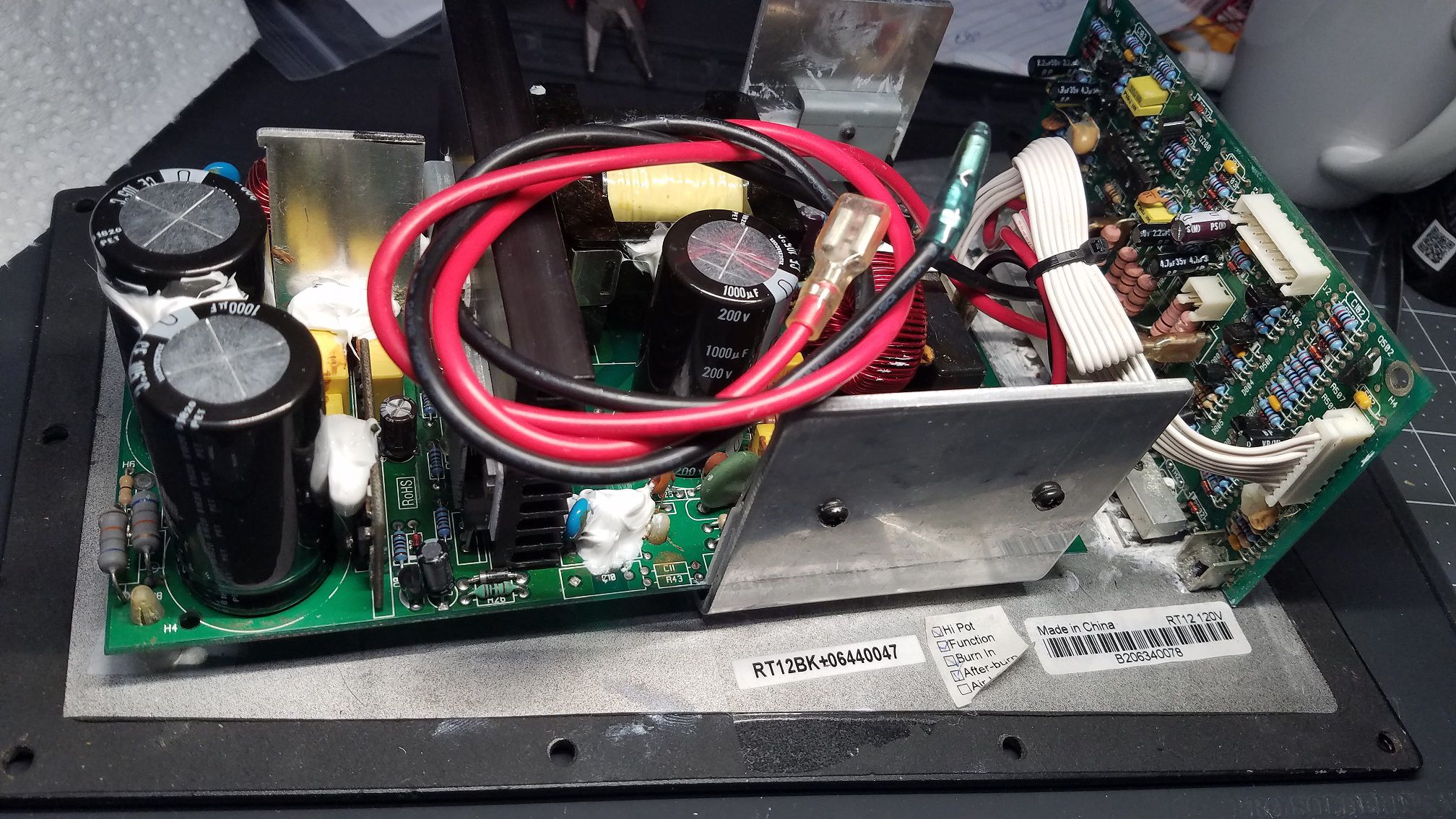
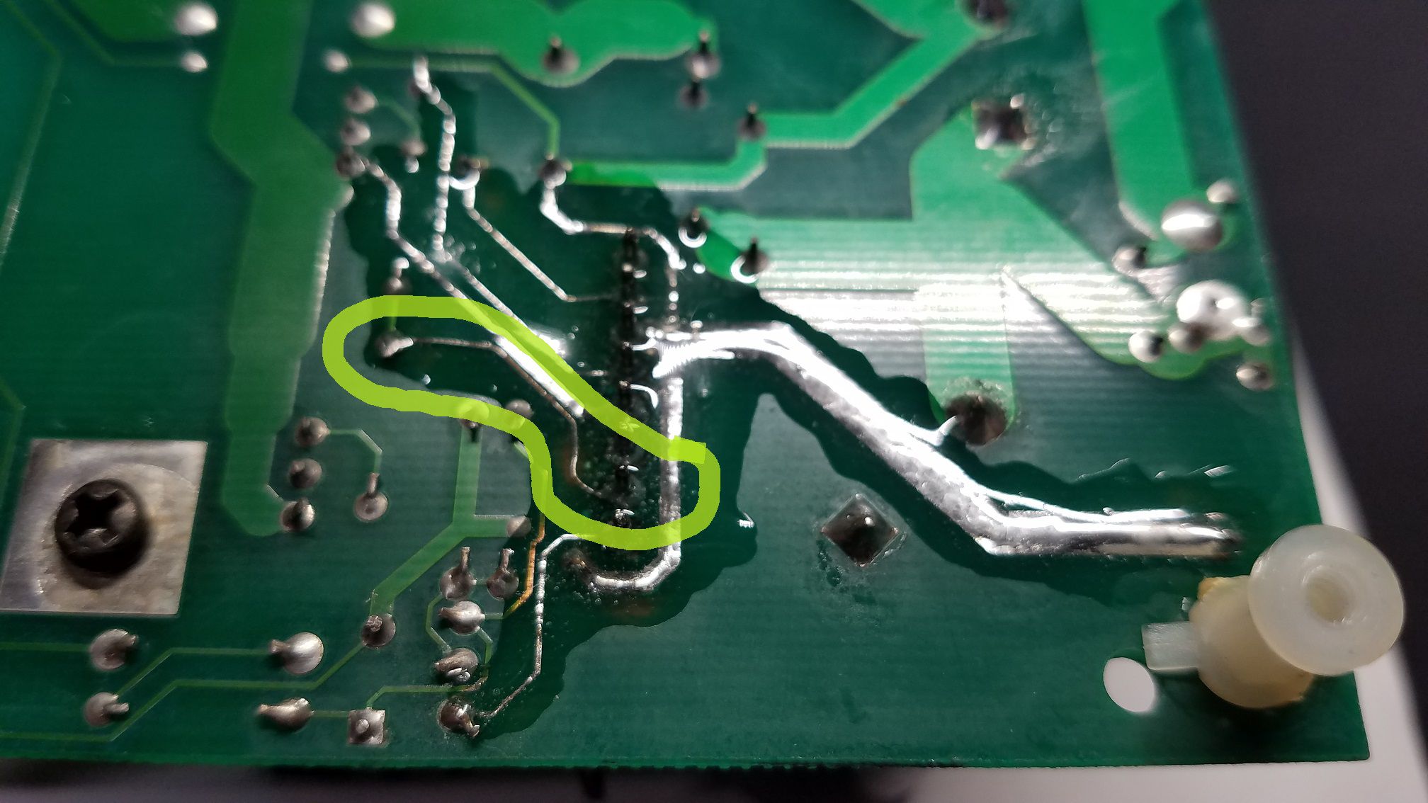
RT12BK Plate serial number B206340078 This amp had some board damage from burnt traces. I repaired the traces and did a full recap after removing all the glue and it is back in service.
-
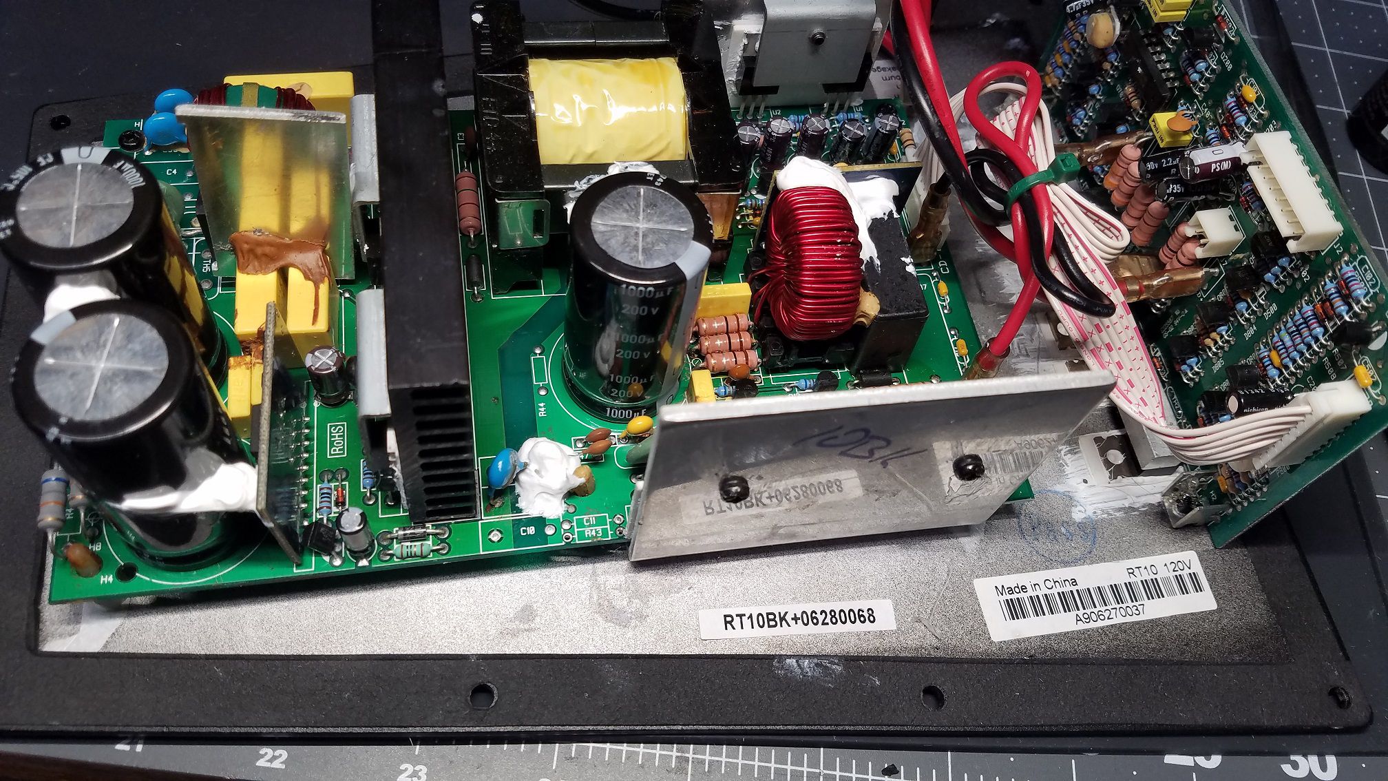
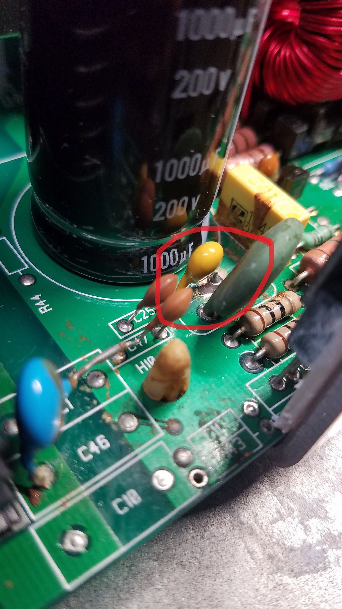
RT10BK Plate serial number A906270037 This amp had a short on the secondary side of the power supply. I had to remove all the glue and replace a ceramic cap. I also did a full recap.
-
RW-10 - RW-10D / RW-12 - RW-12D REPAIR BLOG
ngen33r replied to ngen33r's topic in Technical/Restorations
The boards are 2 layer. If you tear a thru hole off it has to be repaired with a thru hole repair kit and the proper sized eyelet. You can use jumper wires and epoxy, but I consider that a hack job and not a proper repair. Keep in mind this is only if you damage the board. In my experience solder wick almost always tears a pad off of these boards. -
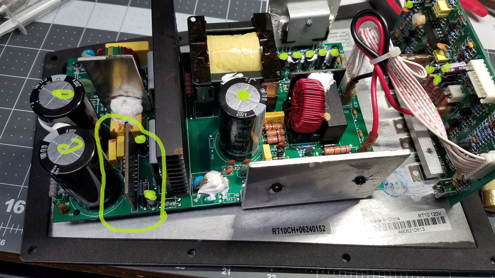
RT10CH PLATE SERIAL NUMBER 06240152 This amp also suffered from a damaged power supply control board and needed to be rebuilt. Once complete, a full recap and it successfully cooked my 10in test woofer. Note to self lower the volume level before connecting an input signal. Some people have their settings way too high!!!
-
RT10BK PLATE SERIAL NUMBER 06270328 This amp was not getting power. The supply control module failed and needed to be rebuilt. I rebuilt the control board and did a full recap on the amp. Now, good as new.
-
RW-10 - RW-10D / RW-12 - RW-12D REPAIR BLOG
ngen33r replied to ngen33r's topic in Technical/Restorations
First all the glued components need to be removed and the yellow glue on the board needs to come off. These boards only have 2 mosfets. You have to do some testing to find the location of the failure. The boards have multiple power supplies after the transformer. You have to start at the end and work your way back to find the issue. Blowing fuses is almost always before the transformer. If you don't have a vacuum desoldering tool, I wouldn't attempt the repair. The boards are made in China and the thru holes rip easily off the board. Thru hole parts don't last very long with vibrations if they are not securely soldered. The only proper way to fix this is to replace the thru hole and resolder. Jumper wires, solder blobs and all of those other types of repairs are hack jobs and should be avoided. These units are getting old, they should be recapped at this point if you are servicing it. -
R115-SW shock when touching back amp plate bolts
ngen33r replied to PurdueBoilers's topic in Subwoofers
Those bolts are for the WA accessory and they are ONLY screwed into the plate. Either a decoupling capacitor shorted, you have a bad wired outlet, or there is a conductive path to the chassis inside the amp. -
RW-10 - RW-10D / RW-12 - RW-12D REPAIR BLOG
ngen33r replied to ngen33r's topic in Technical/Restorations
Anywhere that the glue has started to turn brown needs to be fully removed. The best way to remove it is to use hot air at 150C and a dental pic to remove it when it gets soft. The control board needs to be removed and thoroughly cleaned. The Chinese capacitors on these are about at end of life and should also be replaced, especially if you never power the system fully off. The switch is installed for a reason. The standby mode does not fully power off the unit and I know 99% of us do not turn our subs off. -
RW-10 - RW-10D / RW-12 - RW-12D REPAIR BLOG
ngen33r replied to ngen33r's topic in Technical/Restorations
RW-12D PLATE SERIAL A308380152 This amp had a power supply failure due to the glue used to secure the parts becoming conductive. The PDC board needed to be rebuilt and all the glue removed. The fets were replaced and the power supply was recapped. Parts were secured with GE silicone II.
-
Hello All I have been repairing Klipsch subwoofer amps for about 15 years as a hobby. I have decided to start blogging my repairs and eventually do videos of each one. This thread is intended to be a blog and a resource for information. I will try to answer repair questions as best I can. Comments and tips are also welcome, If you do not have the experience or the tools, PLEASE do not attempt any of these repairs. You will only end up damaging the board and it will end up costing more for a tech to repair the damage. If you do not have a high quality vacuum desoldering station (Hakko or Weller) and a current limited mains supply, you should not be working on these amps. These subwoofers do not have any user serviceable parts inside. If you open up the sub or attempt any repair you see in this thread, you are doing so at your own risk!!!
-
4 Ohm
-
I second this and my personal favorite is an Radio Shack TRUE RMS that I grabbed on eBay for $15. Either way I will confirm the measurement when I am home from work, but I am 95% sure it is 4 ohm.
-
Is R39 on the board burnt? and I'm interested in the amp. I have a driver at home, I believe that they are 4 ohm but I will measure it to make sure.
-
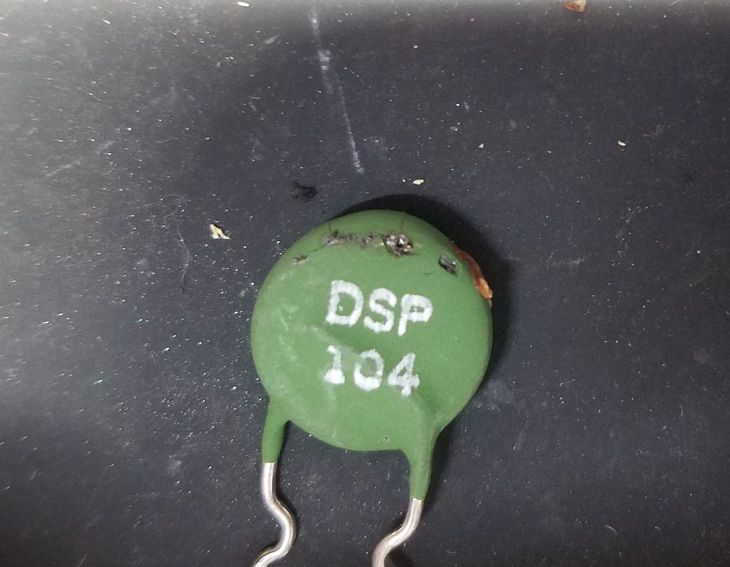
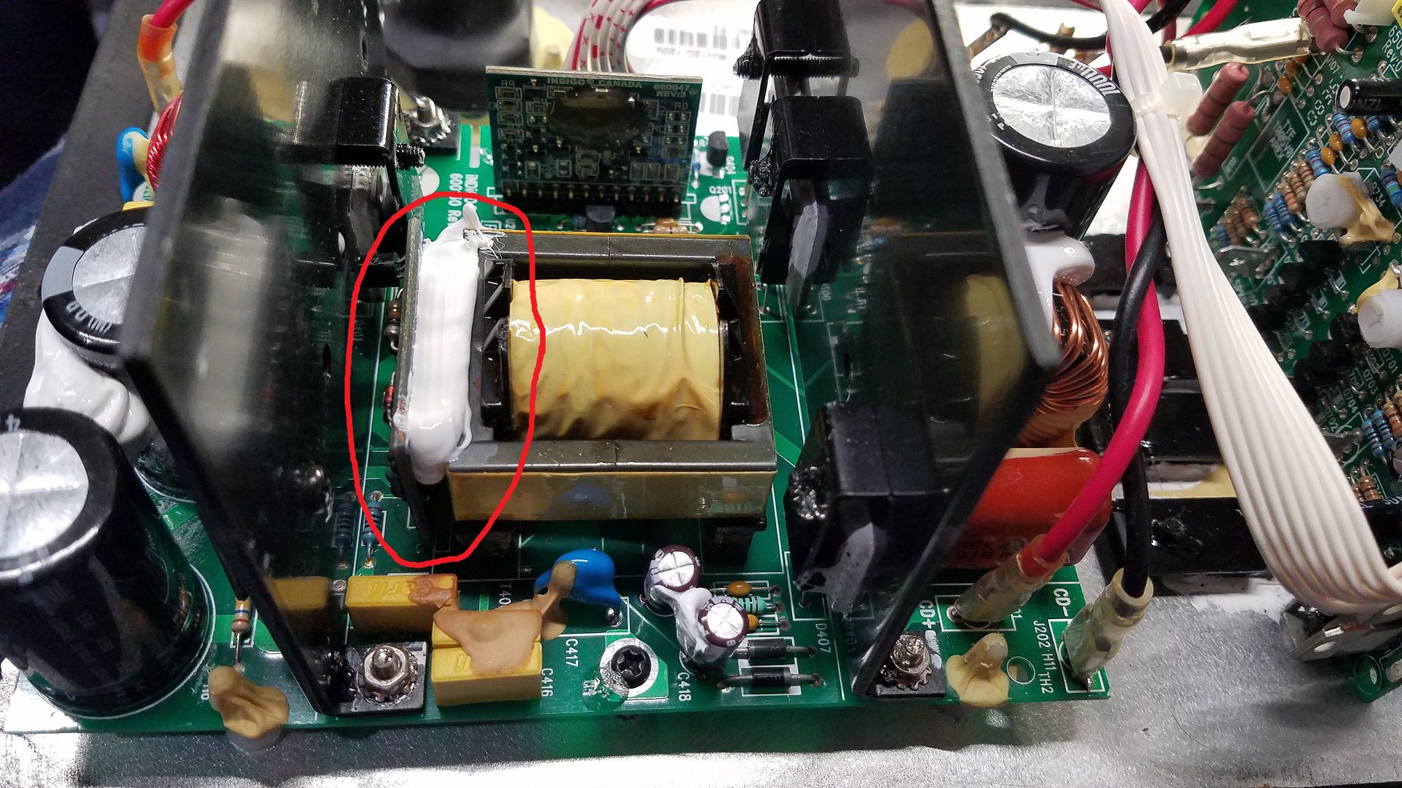
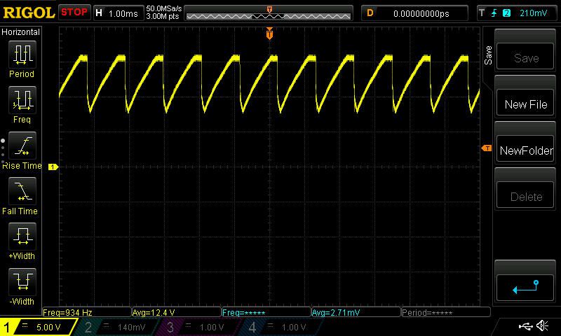
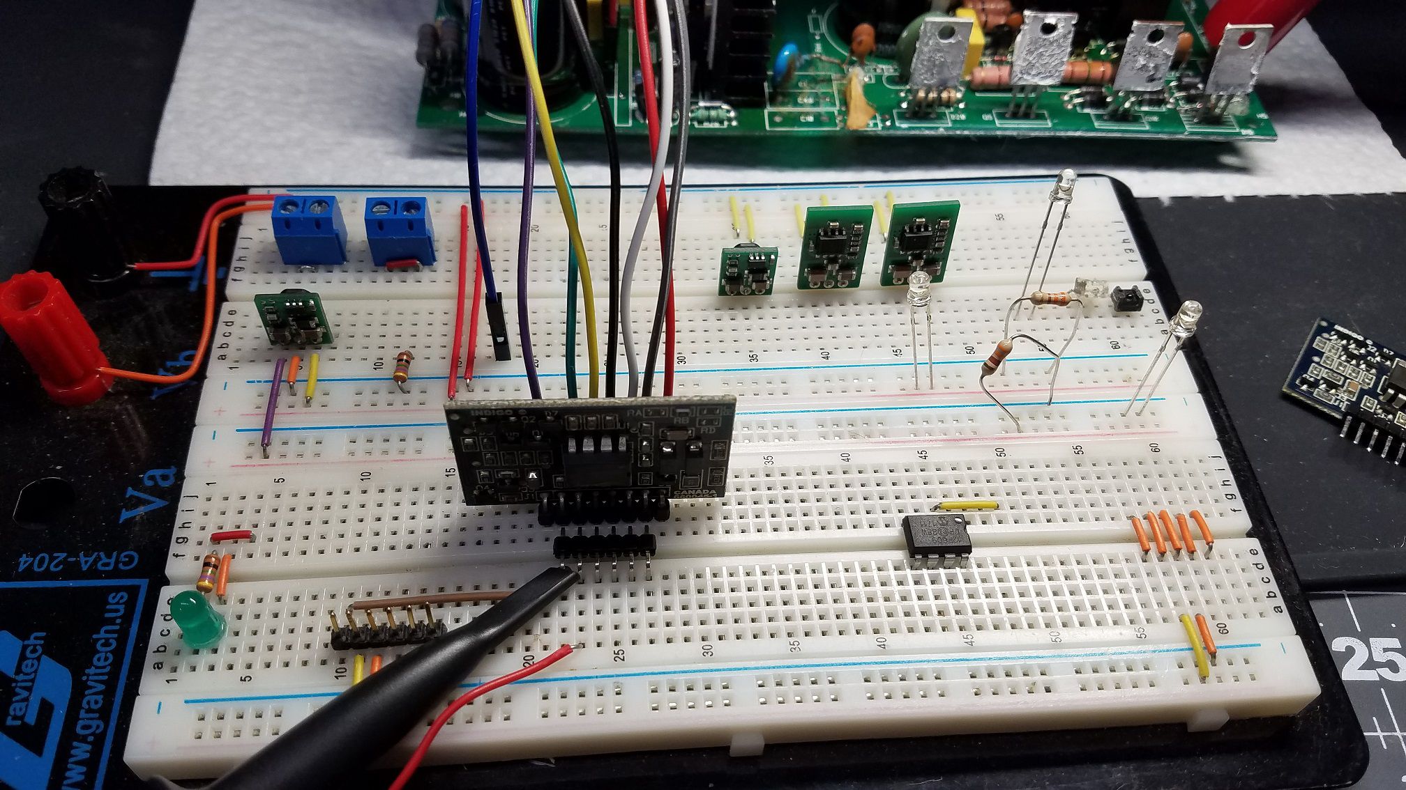
RT-12 Plate serial number 06440047 This amp was not getting any power on the secondary side of the transformer. A know weak point is the controller board 660045-1 failing. This was not The case with this amp. Pin 2 connects to the power supply that is on the board. This pin had voltage, but also a lot of noise. This noise will not let the supply start or properly regulate. The only way to see this is to look at pin 2 with a scope Pin 3 is the common and connects to the negative side of the rectifier. Pin 6 will have over 300V present. If you are poking around and slip, you will do some damage or worse shock yourself. The noise points to a bad capacitor, which is the only thing that pin 2 connects to. Replacing this cap brings the supply back to life. The whole supply will be recapped and it should be good to go.