


STSOE
-
Posts
48 -
Joined
-
Last visited
Content Type
Forums
Events
Gallery
Posts posted by STSOE
-
-
-
Well. Just stop it. If you like your music, stop ruining it.
-
 1
1
-
-
The dsp is a must this time around. I have 3 r112sw and one SVS pc2000. The SVS really ain't that impressive i think. And the Klipsch look really nice. Also the formfactor. I was thinking about SB2000 pro. But i have a hard time deciding.
-
Hey guys.
So i have been looking at the Klipsch C-310ASWi.
I don't remember reading anything about it here though.
Doesn't anyone have a couple of these?
I am quite interested in hearing your thoughts about them.
I have a hard time deciding between these and SVS.
I just really want to stick with Klipsch you know.
Any input will be appreciated.
-
On 12/13/2019 at 8:22 PM, Deang said:
High pass caps and resistors get changed, and a mod that adjusts a resistor value in the LCR (not applicable to the ii and iii). No change to the crossover point, just a dB drop in output at 3.5kHz which reduces ringing from the cones.
I'm really not interested in doing anymore ii's, and won't touch the iii's. I'm tired of the whining and bitching.
Well. That whining and bitching are just from people who whine and *****. I am however genuinely curious how you would do it? And have you heard the lll?
-
 1
1
-
-
16 hours ago, polizzio said:
Tin/lead is likely most common materials in a blend for electric hand soldering. I posted that list just as an FYI on electrically conductive materials, not really soldering elements. And the first four elements are like splitting hairs on conductivity/resistance values. Most of those elements in that list have very high melting points, which would preclude usage in electric soldering. Silver soldering for example requires a torch and temps > 650 C. Elemental silver has a melting point of 962 C. (1763 F)
Any of those elements physical properties can be quickly found on wikipedia.
Reading is one thing. Reading from people with actual experience is another. Thanks for the input though. This thread have been quite useful up until now. I learned a lot none the less. 🙂
-
Spotify? Really? Not Qobuz or Tidal?
-
19 hours ago, Deang said:
Well, stop it.
Why is 2% silver a bad thing?
-
Deang. Just out of curiosity. What did you change on the crossovers you used to make for the Rf's? Did you make it from scratch or did you just alter the stock ones? Just better materials or did you alter the crossover frequency?
You haven't made any for the lll have you?
-
21 hours ago, polizzio said:
Excellent example. The solder makes the actual electrical connection.
This list shows the conductive order of some commonly used metals and alloys, based on equal sizes.
- Pure silver
- Pure copper
- Pure gold
- Aluminum
- Zinc
- Nickel
- Brass
- Bronze
- Iron
- Platinum
- Steel
- Lead
- Stainless steel
Isn't most soldering materials a mix of a couple of those? The melting point of some of those would fry the board would it not?
-
23 minutes ago, Deang said:
‘Inner metallic bond”. That sounds like welding.
The bond should be mechanical. Solder should be used like paint. Yes, it stabilizes the connection, but it should not be creating the connection.
Therefore i was a bit hesitant with using two example, 1 uf caps to achieve 2. Wouldn't it be a lot harder to establish a sure connection using more caps in serial?
-
28 minutes ago, babadono said:
Good solder joints where an inter metalliic bond between the two materials being soldered together has been achieved are good. Bad solder solder joints where said inter metallic bond has not been achieved are well.... bad.
You will never be able to achieve an inter metallic bond with soldering. That would require the to materials being soldered both being made of lead. Otherwise you can achieve a great melting bath with welding.
-
5 hours ago, Deang said:
I think a person can talk themselves into hearing anything (myself included) - I think that guy is a loon. The only person in his house that can hear the things he’s hearing is his dog.
Buy the best built part you can afford and move on. Most everything else is voodoo.
Yes, paralleling caps reduces the ESR a little, but you’re also adding solder joints, so ...
I was thinking about that at some point during my research. How much does the soldering affect things and what should i use to solder a crossover? Isn't lead a bad thing and how much silver can actually be blended into the solder material?
-
5 hours ago, glens said:
1/3 + 2/3 is about the limit of any sort of effectiveness, I'd think. When talk of "bypassing" one cap with another for some effect, when the other is a small-fractional value, I declare that wasting money and pissing in the wind. I've wasted some time looking over that web page and as I recall, he mentions such small-fractional-value "bypass" stuff. If so, he's at least somewhat deluded...
I do agree with you on that one. I can't see how there should be any advantage in throwing in a 1 for example with a cheaper 7.2 or so and then magic happens.
-
8 hours ago, mustang_flht said:
Yes it is not mandatory, but the advantage is to make the exact value you want and also the sound is better because the ESR is lower for 2 compared to only 1. And also because you can mix 2 different brands, look here for tests:
http://www.humblehomemadehifi.com/Cap.html
With 2 you can make a price compromise: a not too expensive capacitor coupled with an excellent, you will have 90% or 95% of the capacitor qualities the best for not too expensive.
ESR here >>> https://community.klipsch.com/index.php?/topic/116879-high-esr-effect-on-crossover-frequency-and-slope/
I know about humble. That is the reason i wanted alumen in the first place. But thanks.
I did not know about ESR though. Thank you for that. Good read.
What you are saying is that if i take an Amber z-cap and an alumen z-cap i will save a lot of $$ and it will sound better? That is interesting.
-
40 minutes ago, mustang_flht said:
You can use 2 capacitors in parallel of different values to find your value of 2.1. For example 1.8μF + 0.33μF = 2.13μF and in addition with 2 in parallel the sound will be better 😉
http://www.learningaboutelectronics.com/Articles/Series-and-parallel-capacitor-calculator.php
😀
I know. But for simplicity i was trying to avoid that.
Why does it sound better?
The Alumen range does have a 1. So maybe you are right that i should get two of does instead. I was trying to keep it as simple as possible, but if you a right that it sound better maybe i should do that.
-
2 hours ago, Deang said:
Well, 2.3 would be over 10%
I've used 2.2s to replace 2s, but they were handpicked to come in at 5-7%, and matched to within 2% by the vendor.
The wiring is soldered to the PCB. You will probably end up lifting the foil from the boards. Well, you've been warned.
I didn't think about it like that. You are propably right. I might as well just find one that is actually a 2.
Yeah, that is true. Well i might give it a shot anyways if i feel like it. I'll decide on that later on.
I might just paint them too, the girlfriend would quite like a satin white.
That would make them speciel, although i can't decide if that is a good thing. 😋
-
1 hour ago, Deang said:
There is no 2uF Alumen, just a 2.2, which might be creeping in on 2.3. I don’t think one is better than the other, they are both film and foil. Well, one is film and aluminum foil, and the other is film and tin foil, but I don’t see that as anything to get excited about.
l wouldn’t mess with the wiring.
You are right about that. But would 2.2/2.3 be such a bad thing?
I think i am going to replace the wiring with wireworld mini eclipse and also the crappy terminals with some WBT.
-
2 minutes ago, glens said:
Still a skeptic for the most part. That being in terms of relatively new parts at any rate.
Well. I don't know if it will be an improvement either. But i think it is worth the time to find out. 🙂
-
4 minutes ago, glens said:
Thanks for the synopsis, Dean. I'd reckon any wound-resistor inductance would most certainly not affect anything below where the tweeter tops out anyway.
So if you bought a new pair of recent Heritage (or Pro with some) you'd yank the caps?
I seem to remember that you were pretty sceptical a couple of pages back? Are you a believer now? 😉
-
12 hours ago, Deang said:
I wouldn't worry about C3. That part is perfectly fine for that position.
A 2uF is going to run very close to 2.1 anyways. Just use a 2uF.
https://www.parts-express.com/audiocap-ppt-theta-20uf-200v-film-foil-capacitor--027-724
This for the 8.2uF
Those are film and foils. If you're going to do this, might as well do it right.
Use Mills resistors. There is only one better resistor and they're overkill for this project. The best source is www.soniccraft.com
Hey. I'm glad you chimed in. I was hoping you would see this thread at some point.
Have you done any Rf7 lll crossovers yet?
I know you where popular with the older ones.
Also very pleased to see that you recommend the Alumen cap. That must mean that i am on the right path at least.
I don't know the Audiocap though. Why not use an Alumen for the 2.1 too? Is the Audiocap better?
And thanks for the resistor recommendation. 👍
Do you have any thoughts on the internal wiring?
-
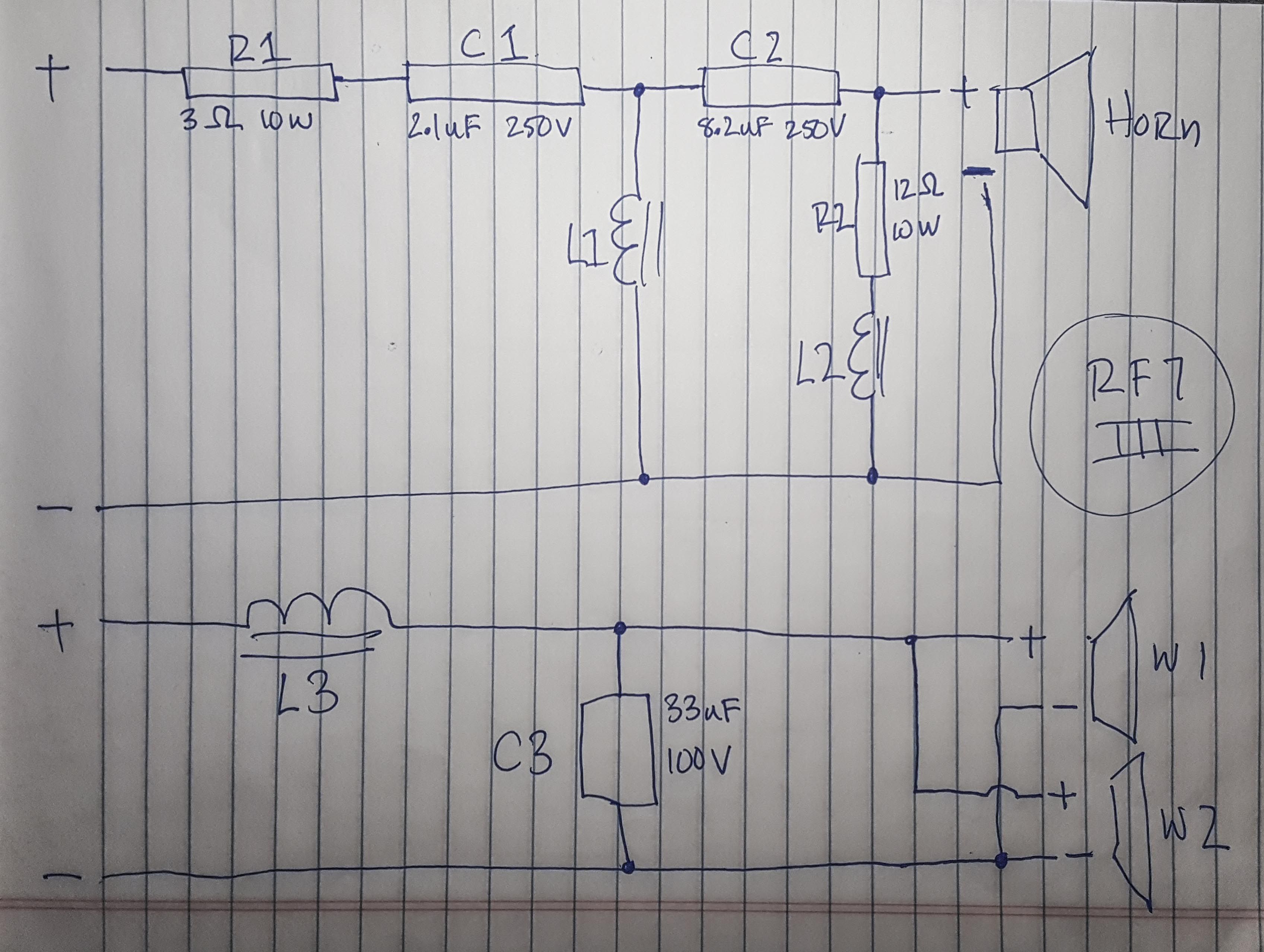
3 hours ago, MechEngVic said:
It looks pretty good compared to other high end Klipsch crossovers, at least it has air cores for the small coils, and no 0.05 cent caps.
Now we just gotta find the coil values. Double check my sketch for mistakes.

Man, i haven't made one of those for years. But yeah i thing you got it right. 👍
-
14 minutes ago, pzannucci said:
Don't forget to swap the in-line resistor to a Mills or better.
I know. But i haven't made a final decision which ones i am going for yet.
-
13 minutes ago, mustang_flht said:
The parallel components have less influence on the sound than the serial components, change first 2.1 and 8.2 μF for a better sound 😉
Exactly. That's why i count on Jantzen on those two and Mundorf on the 33 just because it's a bit cheaper but still resonably good.
-
1
-
MP3 player ideas?
in 2-Channel Home Audio
Posted
There is no good ripper. The last one got a few good ones in. But damn. Don't aspire to be like him.