Yroger
-
Posts
35 -
Joined
-
Last visited
Content Type
Forums
Events
Gallery
Everything posted by Yroger
-
Whaou !!😲
-
Hello, A week ago I bought a used mains power supply with the dsp card and the control panel of an RT10D with the idea of comparing this power supply with the mains supply of my Jamo D600 which is largely similar. I have already repaired (well I think) the RT10D power supply. two of the four mosfets were shorted as well as the two 1µF film capacitors that had exploded. I took the opportunity to replace all the small chemical capacitors that are on this card; many were tired (high esr). On power up everything seems normal, the control panel reacts. On the other hand I have a big plop (in the loudspeaker) at each power-up. I took a voltage reading and there are 360 millivolts DC once the system is running without any source connected to the amplifier input!! Does anyone have any feedback on this? It seems to me all the same that it is quite high as DC voltage. To read to you.
-
Jamo D600/RT - 12D Amplifier Power Supply Circuit Repair
Yroger replied to bricol67's topic in Technical/Restorations
Information and various tests carried out so far have failed to bring this active subwoofer back to life. The main power board seems operational and unfortunately for the time being, no clue on the causes of the failure seems to be looming on the horizon. Thank you very much to Bricol67 for the time spent -
Bonjour, Il faudrait en premier contrôler le primaire de l'alimentation de l'ampli (pont de diode condensateurs de lissage) puis regarder les deux petits fusibles rond type 382 de l'alimentation régulée.
-
You have to look at the second-hand market and buy a broken box at a low price to recover parts but with the risk that the defective components are the same you will have to ask the seller about the failure encountered with his box and that this one is different from yours.
-
With a Peak DCA75 analyzer he confirms to me that it is an operational BJT pnp with a gain of 200 ! the components have been desoldered is tested individually; it is no longer to understand it.
-
Jamo D600/RT - 12D Amplifier Power Supply Circuit Repair
Yroger replied to bricol67's topic in Technical/Restorations
I have no good news because all the components are good !! -
Jamo D600/RT - 12D Amplifier Power Supply Circuit Repair
Yroger replied to bricol67's topic in Technical/Restorations
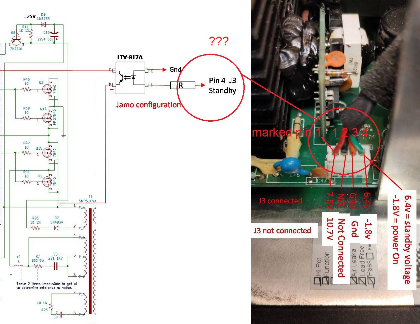
Ok so Q4 shunted and J3 connector configured in standby mode (pin 1 - 4) here are the voltage measured on connector J2 (power supply only)
-
Jamo D600/RT - 12D Amplifier Power Supply Circuit Repair
Yroger replied to bricol67's topic in Technical/Restorations
Ok pourtant avec le multimètre c’était bon ! Je regarde cela demain matin. Bonne soirée. -
Jamo D600/RT - 12D Amplifier Power Supply Circuit Repair
Yroger replied to bricol67's topic in Technical/Restorations
D3: (standby mode): 16v D3 (power on mode): 16v MMBT4403 (standby mode): 15,4v MMBT4403 (power on mode): 15,4v -
Jamo D600/RT - 12D Amplifier Power Supply Circuit Repair
Yroger replied to bricol67's topic in Technical/Restorations
Yes the voltage changes as indicated in previous post 0V to 16V but I use a jumper between pins 1 - 4 and 3 - 4 to change mode! -
Jamo D600/RT - 12D Amplifier Power Supply Circuit Repair
Yroger replied to bricol67's topic in Technical/Restorations
you must check the transistor Q4 and Q2 + R1 and R2. It's good diode test !! 16V ok -0.5v nothing no reaction: 0v ! -
Jamo D600/RT - 12D Amplifier Power Supply Circuit Repair
Yroger replied to bricol67's topic in Technical/Restorations
Hello Bricol67, I confirm mains supply only by simulating a standby switch the voltages remain present as indicated post of 06.11 at 17:13 -
Jamo D600/RT - 12D Amplifier Power Supply Circuit Repair
Yroger replied to bricol67's topic in Technical/Restorations
I admit being a little lost with all these pins and connectors connected or not .... If this is indeed the case, that the voltages on J2 do not go to 0, with a voltage of 8V on the standby pin of J3, your power supply is not working correctly. in fact the standby pin on J3 and 1 ?? On your modified diet diagram posted on 10.11 at 07:44 PM, you noted: pin 4 J3 stanby ???
-
Jamo D600/RT - 12D Amplifier Power Supply Circuit Repair
Yroger replied to bricol67's topic in Technical/Restorations
Hello Bricol67, In fact, you have to measure between the negative of C49 and terminal 1. With the J3 connector plugged in, you should find about 0.5v or 0.7v. It's good I measure - 0.5v With connector J3 unplugged this voltage should increase to about 10 to 15 volts. It's good I measure 16v I have more and more the impression that the mains supply is not the cause of the failure. Little additional information: (fully connected amplifier, ready-to-use subwoofer). When the power is turned on and there is no signal applied to the input, the loudspeaker goes boom boom and the control panel does not light up ! If I disconnect J3 and repeat the operation the speaker generates hiss instead of the boom boom and the control panel still does not react ! Roger. -
Jamo D600/RT - 12D Amplifier Power Supply Circuit Repair
Yroger replied to bricol67's topic in Technical/Restorations
It seems to me there is a problem with the polarity of the diode bridge and the C49 C50 capacitors on the diagrams posted in the discussion thread !! In our case it is the positive of the diode bridge as well as the positive terminal C50 which are connected to C46 ... -
Jamo D600/RT - 12D Amplifier Power Supply Circuit Repair
Yroger replied to bricol67's topic in Technical/Restorations
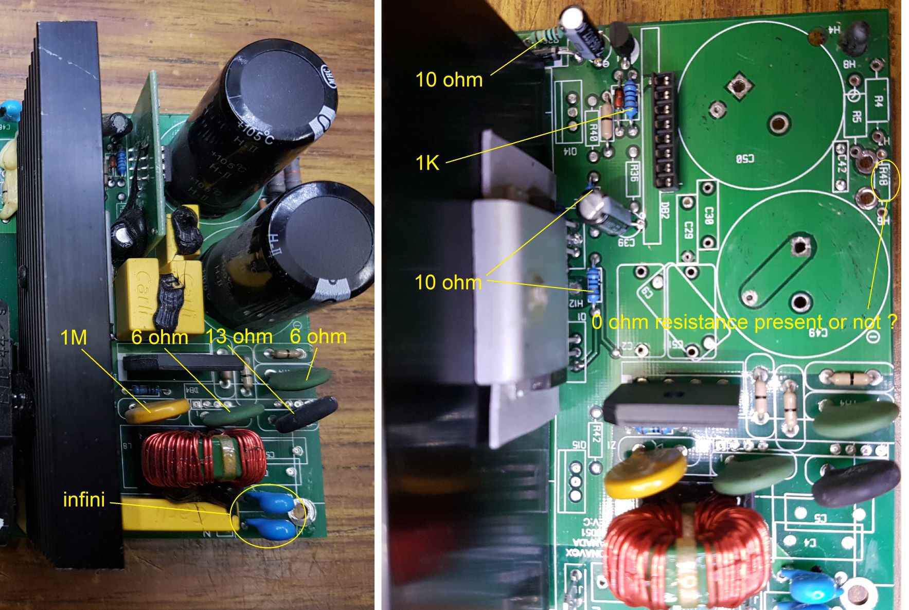
For the R48, I have trouble seeing in the photos I took, but I don't have the impression that it is there. But I noticed that there are small differences between the Klipsch and Jamo power supply I also think there was none. For the test carried out previously it must be kept in mind that all the capacitors and various components and control boards have been resoldered !! Measurement taken between pin 1 DB2 card and capacitor C50. Only the control panel is not reconnected !
-
Jamo D600/RT - 12D Amplifier Power Supply Circuit Repair
Yroger replied to bricol67's topic in Technical/Restorations
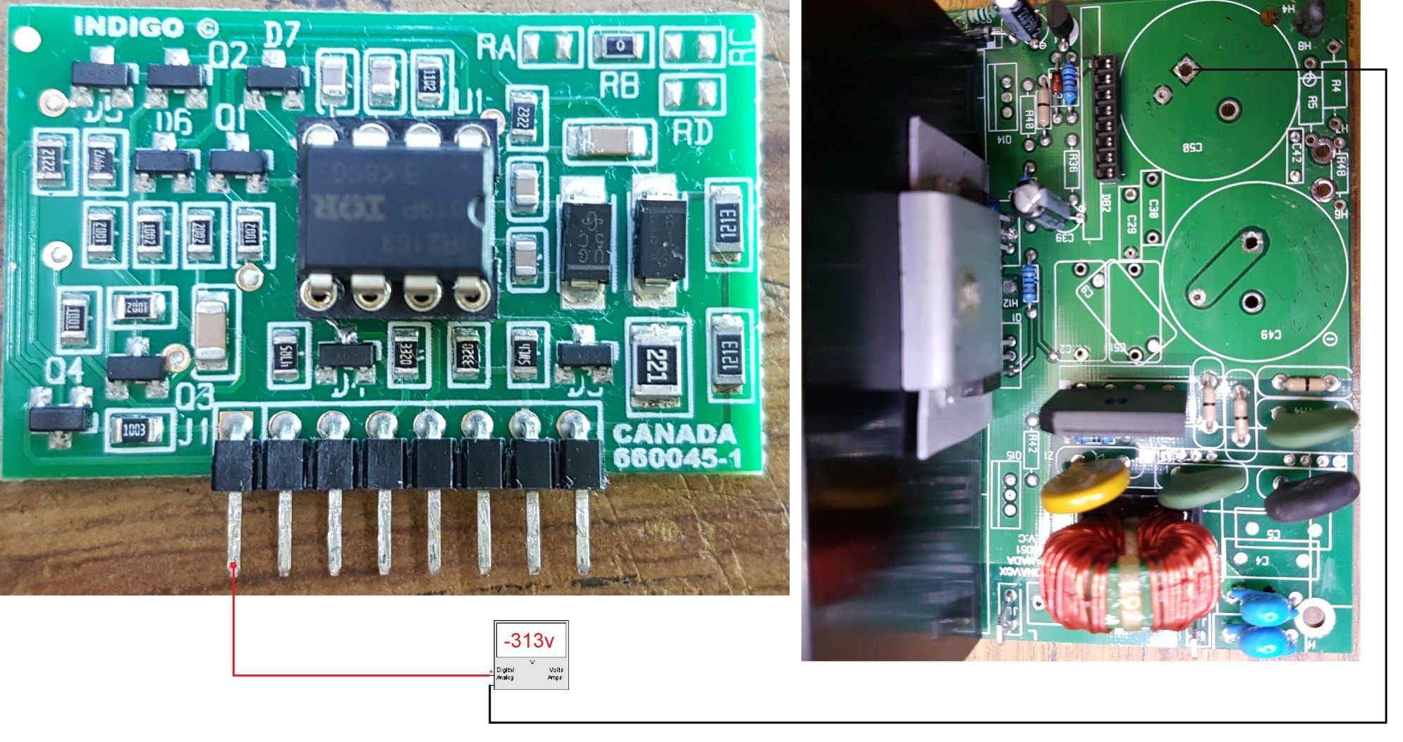
Quick question: Is the 0 ohm resistor (R48) present on our power supply ? I have a doubt !I have a voltage of -313V J3 connected and 292V J3 not connected. I replaced the IR2153 and it's the same. I took the time to do the little assembly to test the IR2153 posted by Journey on page 6. They are ok !! -
Jamo D600/RT - 12D Amplifier Power Supply Circuit Repair
Yroger replied to bricol67's topic in Technical/Restorations
I'm sorry, I can't take the measurements anymore. The owner recovered the subwoofer. I can always help you repair your subwoofer. Do not be sorry because you have allowed me to make good progress in the search for the defective elements of this amplifier. To be sure, you have to desolder the diodes or the resistor in series. It's the same for resistors, you have a parallel series connection. Yes I know the principle but good rather than desoldering them if you had still in your possession the power supply it would have been easier; shame. Have you checked the voltage on terminal 1 ? Did you replace the IR2153 ? Not for the moment I am waiting to receive 3 capacitors of 1000µF 200v to replace C49, C50 and C20 as long as to replace them I take this opportunity to increase their capacity a little (there is room). For the Jamo version of this power supply we had two 680µF and one 470µF Thank you very much for your work !! -
Jamo D600/RT - 12D Amplifier Power Supply Circuit Repair
Yroger replied to bricol67's topic in Technical/Restorations
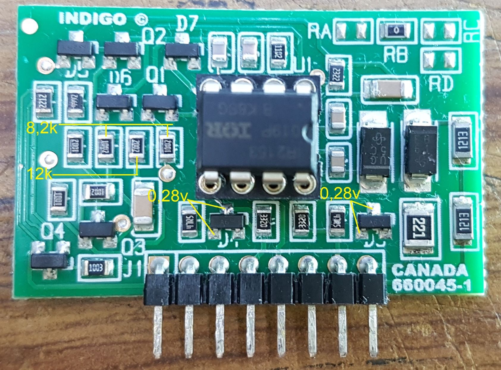
It seems to me there is a problem with the two diodes D3 and D4 I measure 0.28v in both directions (multimeter function test diode) The two 10k resistors gives 8.2k and the 20k gives 12k Could you check all these points? Thank you.
-
In the continuity here are some tests: - The transistor Q8 the diodes D7, D9 have been soldered and checked ok !! - The resistance straps are ok !! - The filtering condensers are all ok !! - - To simplify subsequent maintenance I soldered a connector for the 660045-1 card and visually I did not see anything burnt on it !!
-
Jamo D600/RT - 12D Amplifier Power Supply Circuit Repair
Yroger replied to bricol67's topic in Technical/Restorations
Okay ! -
Jamo D600/RT - 12D Amplifier Power Supply Circuit Repair
Yroger replied to bricol67's topic in Technical/Restorations
on J3... -
Jamo D600/RT - 12D Amplifier Power Supply Circuit Repair
Yroger replied to bricol67's topic in Technical/Restorations
j3 not connected (switch position on): -2.3v (orange and green) and 10,7v (red and orange) j3 connected (switch position on): 7,1v (orange and green) and 8,7v (red and orange) I also listen to a slight crackle when I turn on the power and I wonder if this is not what echoes in the speaker ! -
Jamo D600/RT - 12D Amplifier Power Supply Circuit Repair
Yroger replied to bricol67's topic in Technical/Restorations
Small question always with the hp and the control panel connected ?