Langston
-
Posts
148 -
Joined
-
Last visited
Content Type
Forums
Events
Gallery
Everything posted by Langston
-
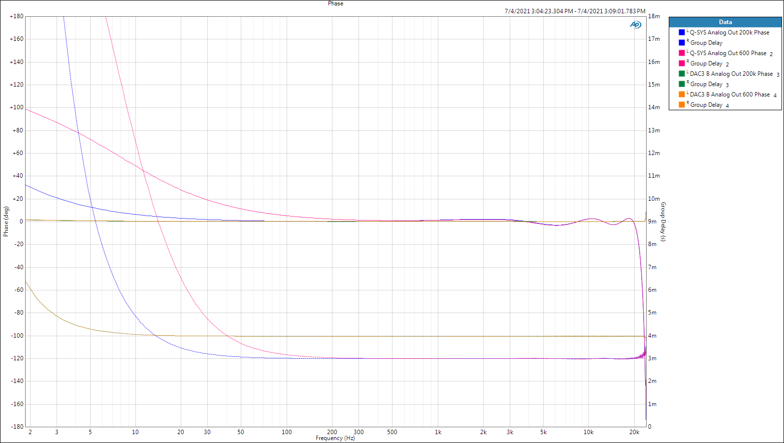
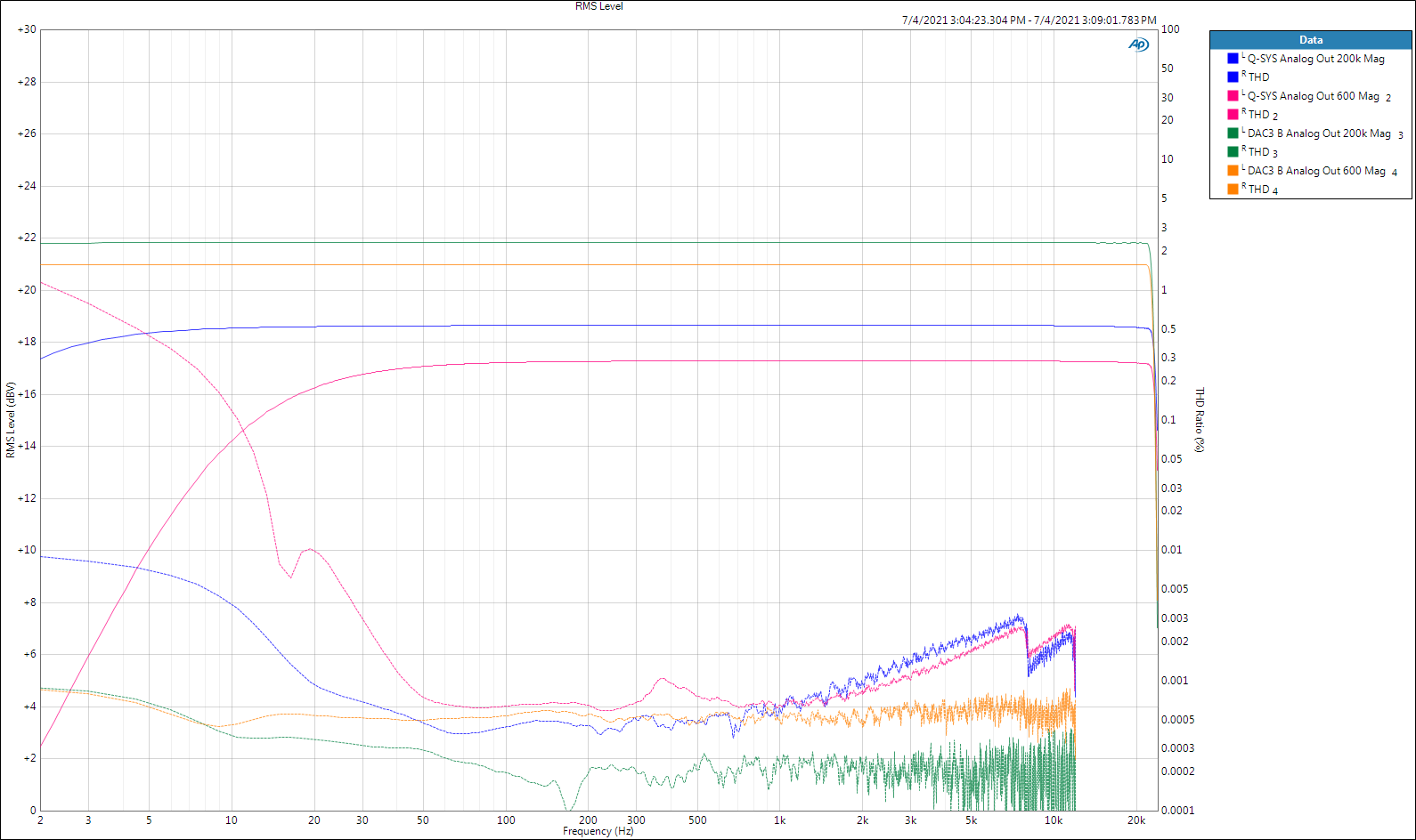
I finished the acoustic domain modifications to my Klipschorns and now I'm working on the electrical stuff. I thought the following measurements might be of interest. They compare the very well-behaved analog output of my Q-SYS Core 250i processor to the analog output of a Benchmark DAC3 connected to the processor's AES3 (digital) outputs. In both cases the processor's AES3 inputs were used to isolate the behavior of the analog outputs. Two loads were used, an easy to drive 200kΩ and a very difficult 600Ω. 48kHz sample rate, 24bits. The Benchmark product, as usual, is in keeping with its namesake. Magnitude vs. THD at 0dBFS Phase vs. Group Delay at 0dBFS God bless you and your precious family - Langston

- 1 reply
-
- 2
-

-
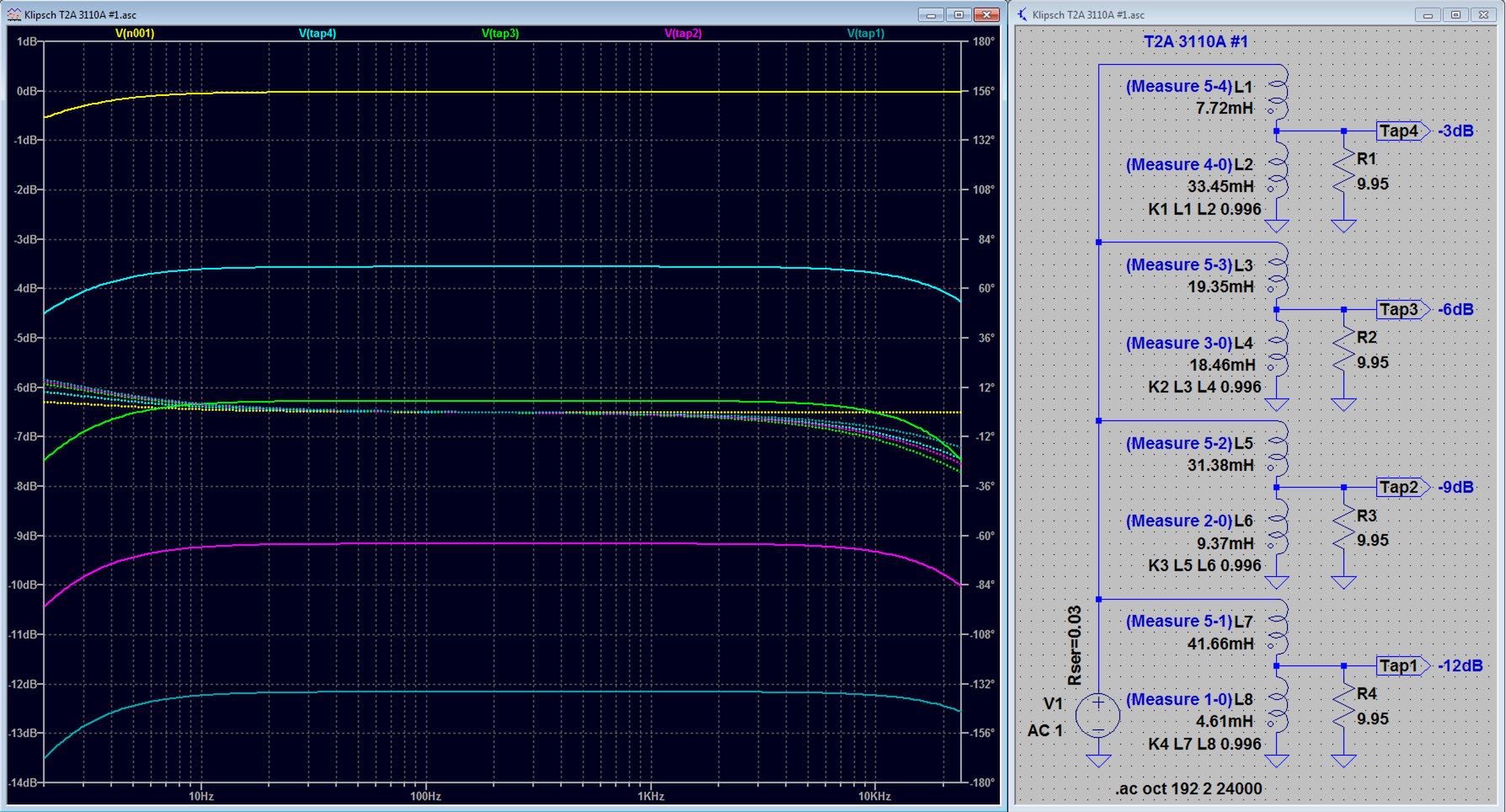
@John Warren 's screenshot unlocked the door for me. Now I'm able to use autotransformers in LTSpice with more than enough accuracy for loudspeaker design. Thanks! : ) I'm getting better than 0.1dB correlation to measurements above 10Hz and phase is close enough as well. You do have to use measurement to derive the proper "K factor" for the Spice Directive to get the high frequencies right. The error I was making was attempting to measure inter-tap inductance values. You have to do what John did and make the inductance (and DCR) measurements from each end of the winding to the tap of interest. Here's my LTSpice file for anyone following along: Klipsch T2A 3110A #1.asc Simulation Measurement God bless you and your precious family - Langston
-
What happens to frequencies less than rated range?
Langston replied to psykoticboss's topic in 2-Channel Home Audio
Somebody just woke me up with her snoring, so I'm going to tinker with this. I'm worse, but it doesn't wake me or her for some reason. : ) A low pass filter allows lower frequencies, a low cut filter (also called a high pass filter) blocks low frequencies. I assume the latter is what you are referring to when you're hoping that something in your system is disallowing music with frequency content less than your loudspeaker can properly reproduce. Low cut filters are used on each passband (woofer, midrange, tweeter, etc.) of loudspeakers intended for concert production because those systems are driven near their physical limits (heat and excursion, or how far the driver is allowed to move). Low cut filters are also seen in home audio systems, but rarely for woofers because their physical limits are rarely approached, cost is much more of a factor and because these filters introduce phase errors that compromise the quality of low frequency sound if not done carefully. Low cut filters are used in home audio subwoofer systems that are expected to be driven to their limits. The answer to your not-so-simple question, Part 1 It's physics, but it's not hard and wildly entertaining to nut cases like us, so hang in there. Of the two loudspeaker failure modes; over-heating and over-excursion, over-heating is by far the more frequent loudspeaker killer. In home audio this kind of heat build up during long-term, very loud music playback isn't likely as it would cause permanent damage with your neighbors quicker than your loudspeakers. BUT if your amplifier is large enough and you drop a needle on a record or crank the volume to 11 during movie explosions, you may cause permanent damage to the woofer due to over-excursion. This damage is extremely rare even after doing something dumb (personal knowledge borne of much experience). Why is damaging over-excursion so rare? Because the physics of moving coil loudspeaker systems limits excursion below the region where the loudspeaker can reproduce sound. The answer to your not-so-simple question, Part 2 Your woofer can move only so far outward from rest, or inward from rest, before it is damaged. Your woofer also produces a range of frequencies, and as you go lower in frequency, it has to move further in and out to produce a constant sound pressure level (flat frequency response). It just so happens that a loudspeaker driver has to move four times further in and out as frequency reduces by half. This quadrupling of excursion to maintain flat sound pressure level or frequency response is a 12dB per octave increase in excursion. Say your loudspeaker is flat down to 45Hz, then rolls off at 12dB per octave under 45Hz. THAT MEANS THE WOOFER STOPS INCREASING EXCURSION UNDER 45Hz. Yea! Thus if your loudspeakers sound good at the volume you are playing, there's nothing bad being done to the woofer at frequencies less that what you are hearing. BTW, it's most likely that your loudspeaker system rolls off by at least 24dB per octave, thus excursion is actually reducing as frequency decreases under 45Hz, thus all is well. So don't worry, be happy. : ) God bless you and your precious family - Langston -
Also interesting is that the Spectrogram plot is the standard (not excess) group delay plot flipped backward and turned 90˚ with the addition of SPL. Source. God bless you and your precious family - Langston The thing we call time in audio measurements and the thing we call frequency are different coordinates for describing precisely the same signal. - Richard C. Heyser
-
On the correspondence between grey/red trace, I think you got lucky. : ) I'm confident the math in LTSpice is correct and when it gives me different answers than what my measurements say, I know I screwed up. In this case I just don't have the knowledge and equipment to fully characterize a transformer correctly. I did study the issue out and found that it's (surprise) pretty involved, OTOH, simply dropping an impedance measurement (DATS is very good if used correctly) into a Spice Directive gives me results that are dead-on compared to real measurements. So why the bother characterizing this leaf when you can have the whole tree with much less effort? If you do figure out this leaf, please let me know how you did it - it'll be fascinating. : ) God bless you and your precious family - Langston
-
Identical results again. Whatever you're doing wrong, I'm worse. : )
-
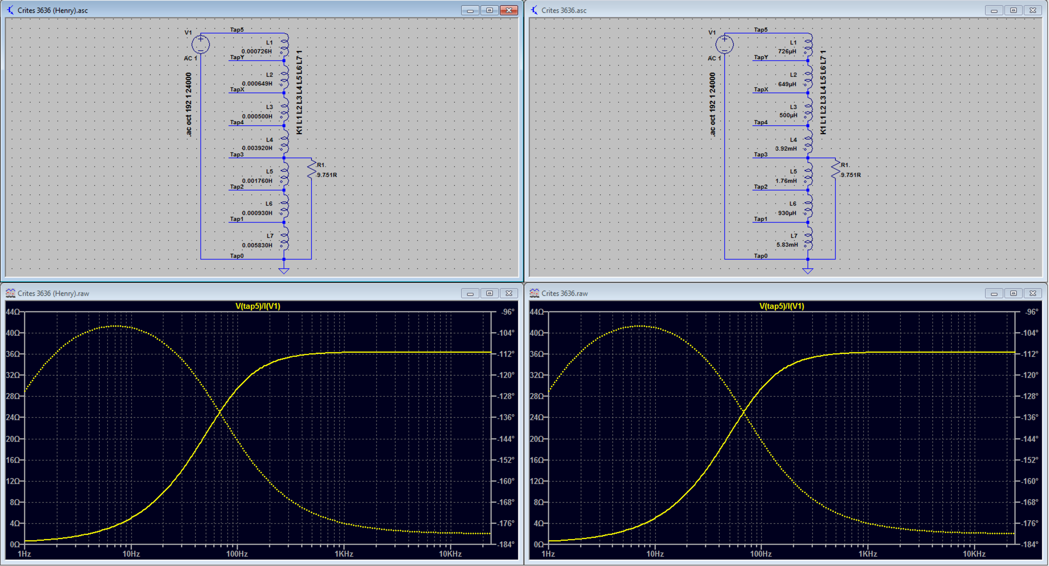
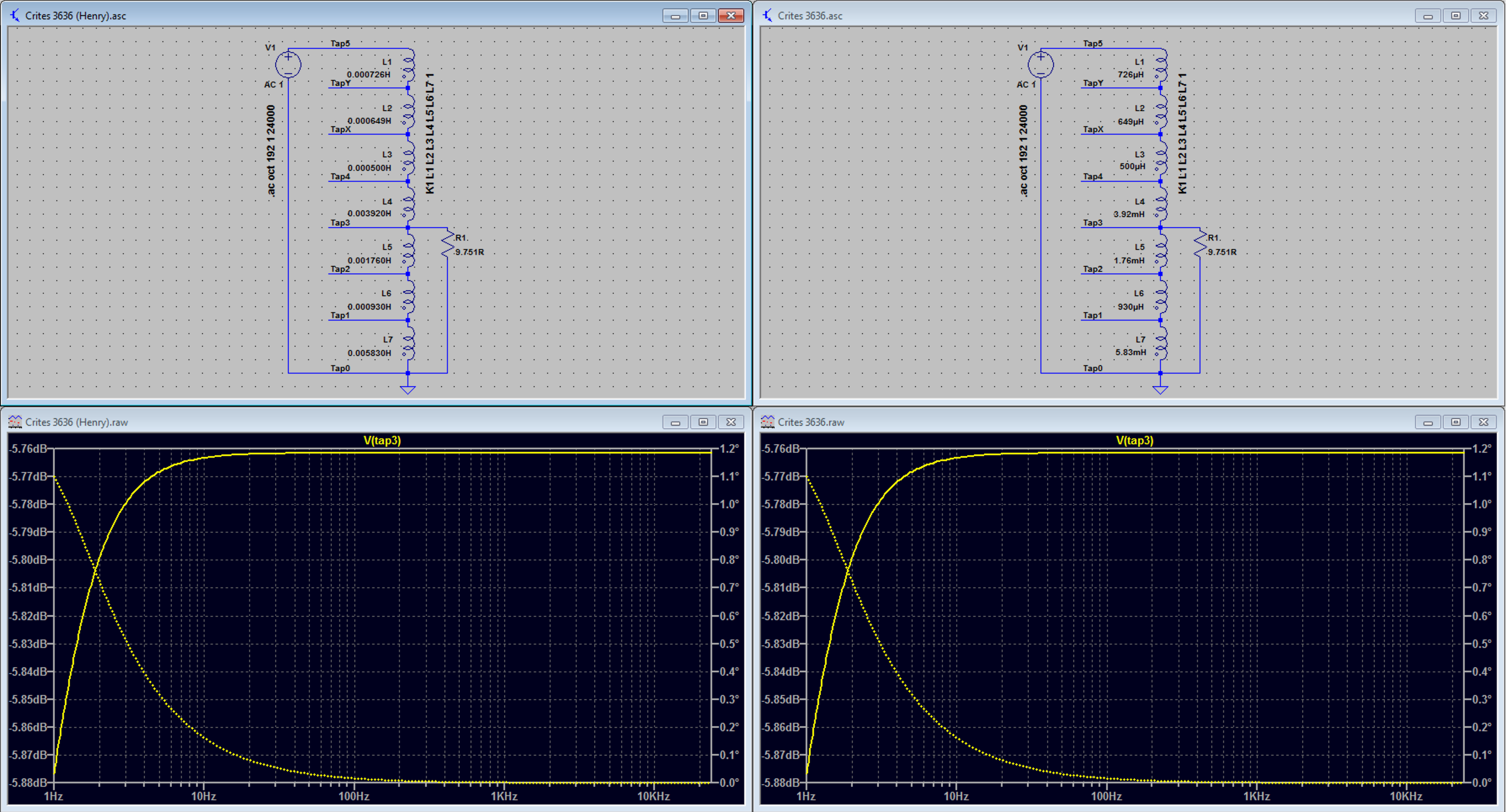
Yep. In real life the 3636 is flat as a pancake through the audio spectrum, yet the sim. shows LF rolloff. I know that LTSpice assumes "typical" component parasitics in many cases, all of which you can change or override, but that's over my head and beyond my interest. I use this software for quick and easies, and move on to other methods that match measurements when it lies to me - such as with these autotransformers. I'm all in though if you do the work - I'd be glad to be your beta tester. : ) Beta test: I changed 3636 inductance values to full Henry units and didn't see any change (which I'm thankful for because I have dozens of LTSpice models where I used various units out of convenience). See if the attached is what you're talking about.. Strikethrough Edit: I did this too quickly and didn't pay attention to the autoscaled Y-axis in LTSpice, which actually shows the autotransformer with a much flatter transfer function than reality. The LTSpice sim also shows quite a bit less attenuation than reality, further indicating it's assuming no parasitics. I matched the LTSpice scale of my measurement of the actual AX used for the sim with the same load and attached it below. God bless you and your precious family - Langston
-
I threw up my hands in surrender trying to accurately characterize transformers and autotransformers in LTSpice or elsewhere. I figured out how to get LTSpice simulations that matched measurements involving these gizmos connected to loudspeakers another way. All you have to do is measure the impedance of the transformer connected to the load (loudspeaker). Then use @mboxler 's Spice Directive to enclose that measurement inside a two-port component (two wires) of your choice. Of course you can do this with just the loudspeaker if you're not using an autotransformer. Here are the directions. It's easy. I then export the voltage response (includes phase) from LTSpice (click simulation window, File, "Export data as text"). I import this voltage response into my crossover design software and combine it with the acoustic response to verify the design without having to buy and build stuff first. The primary benefit of this for me (you can do all this without LTSpice of course), is that LTSpice makes it simple to see the wattage through resistors, voltage across caps and current through inductors. No more "what's that smell?" after Another Brick in the Wall at proper volume. Necessity is the mother of learning how to use a new tool. : )
-
Very helpful info @Dave A, thank you. I bought the DCX464 instead of the DCX462 because I was pretty convinced that the 2 inch Tractrix horn wouldn't work as well as the 1.4 inch ME464 horn that B&C designed specifically for the driver. Tonight I triamped (it's so much easier to go fully active when experimenting) the DCX464/ME464/Khorn. 6th order acoustic LR crosses at 500Hz and 4kHz and it was the first time another loudspeaker system approached the depth and accuracy of my highly modified '84 Martin Logan CLS system. The previous best Khorn mod was the DE750/Tractrix. I think a large part of the improved imaging is due to the large horn's superior pattern control (thus reduced boundary reflections). The sweet spot is much wider as well, though the Tractrix was great compared to head-vice electrostatics. : ) My guess is that the K-402 would be better still - I'd love to find a pair to purchase. God bless you and your precious family - Langston PS: Thanks for the link! You guys are so helpful. : ) Edit (2 days later) 1. I made two improvements on the DCX-ME464 combo, I reduced the mid/high cross to 3.8kHz, which reduced the required delay of the highs to almost zero (zero would have worked w/o issue) and reduced the EQ required for a smooth crossover. Secondly I reduced the lowpass frequency to 375Hz and the mid/high to 400Hz. I couldn't hear an improvement on the first change, it simply measures better. The second change made a dramatic improvement that makes me want to go down further to see if it would make things better still. The low end is tighter, a little warmer, more even throughout the room and apparently louder. "Apparently" because it isn't louder, my guess is that it's just working with the room better now that more of the low end is controlled by the big B&C horn. That horn is also responsible for the cleaner imaging due to fewer wall/ceiling reflections. I had to raise the mid/high passband 2dB to maintain balance with the bass output due to this change. 2. I then went back to the DE750/Tractrix combo again and tweaked its processing based on what I learned above and now prefer it again. My guess on this is that the Tractrix horn's lack of abrupt transitions is responsible for the better sound. I've worked on the early reflection room surfaces a bit to help given the smaller horn's inability to maintain pattern control very low. The big B&C horn measures better and has a larger sweet spot, but it just doesn't sound right even with FIR filtering. The DE750/Tractrix sounds extremely good even before FIR filtering. After FIR filtering it's so good that I'm actually happy with the loudspeakers! The horror! : ) God bless you and your precious family - Langston
-
I see your 350Hz point! Please give me everything else you have or I'll, I'll.. err. Please! : )
-
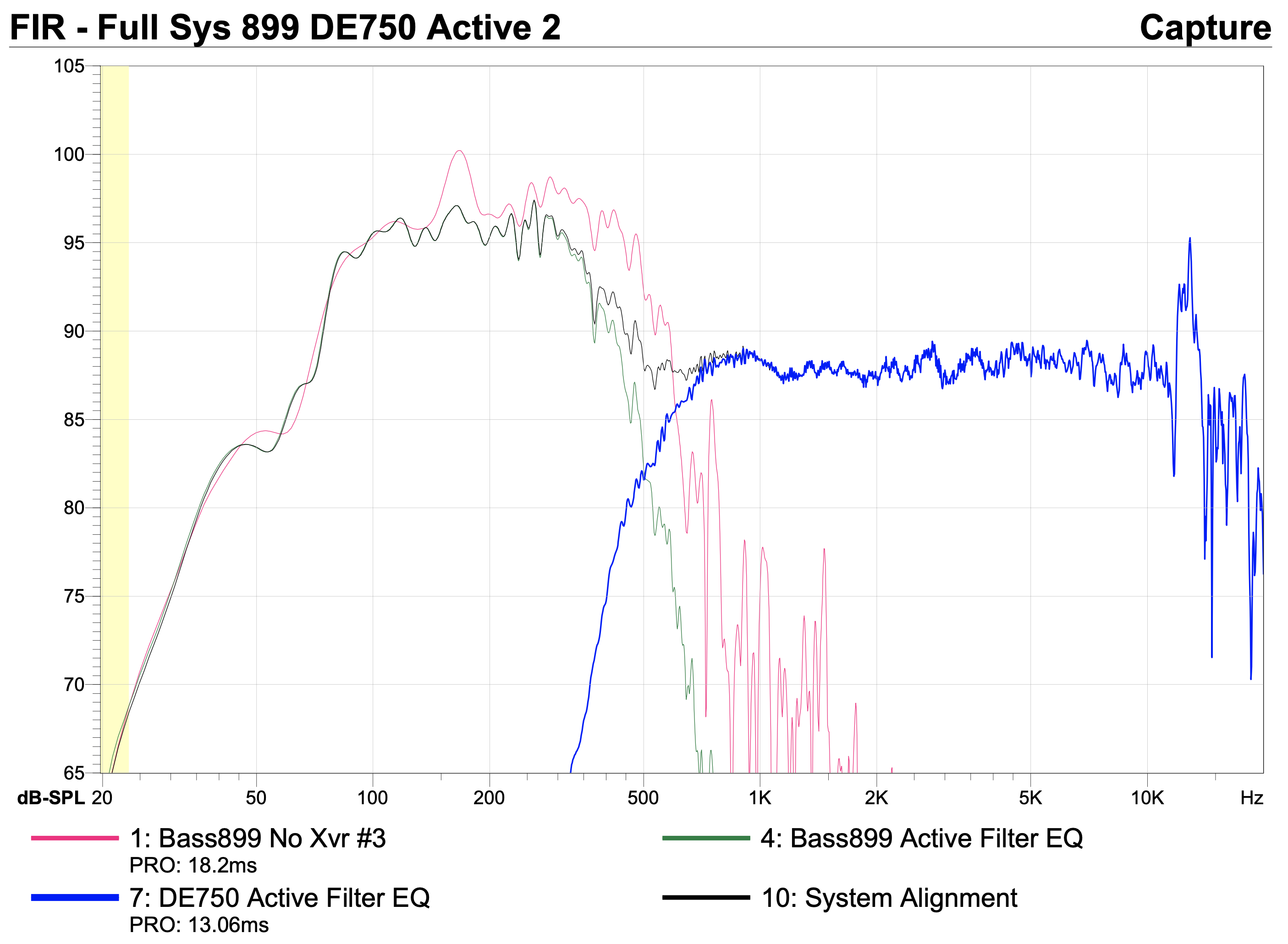
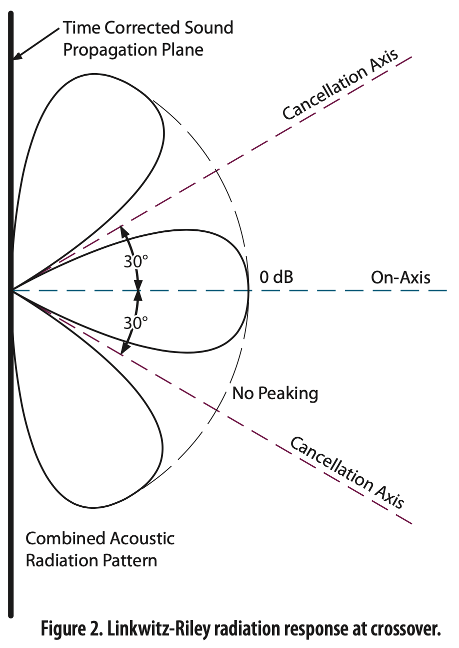
With my Khorns the raw response drops above 500Hz (pink trace). This is an outdoor reflection-free measurement using a false wall per Dope From Hope. The green trace is an acoustic 6th order LR low pass, down 6dB at 400Hz. Though the DE750/Tractrix is comfortable with a mirror alignment at 400Hz, I chose 500Hz because I'm running the HF passband about 7dB lower than the bass per my taste. Actually 2dB acoustically, the 7dB was the electrical HF reduction required to achieve this. The bass skirt of course widens as you go down, so I prefer increasing the HP cross frequency to maintain overlap per the LR design, which results in its superior polar response (coherent forward lobe with nulls toward floor and ceiling). IOW, it sounds cleaner. Cranky! : ) God bless you and your precious family - Langston PS: Rane Note 160
-
Actually B&C does mention it at the bottom of the crossover page. Both drivers are approved for this mid/high passive crossover as long as they are the 8Ω models and use the ME464 horn. It's my guess that you can remove the 1.4 to 2 inch adapter built into the DCX462 to fit a 1.4 inch horn such as the ME464. I love to hear from someone that's done this successfully. Passive crossovers have to deal with both the acoustic output and variable impedance of the driver/horn system, thus it's very likely you'll want to modify component values a bit with a different horn, such as the Tractrix. If you are just getting started with loudspeaker design this is a deep (and as you mentioned, expensive) pool to begin with. : ) If I find the DCX464 is the end game driver for my Klipschorns, it's likely I'll cross the mid/highs passively and biamp between low/mid. I hope I can cross the low/mid passively without audible compromise, but I'm bettin' against it. God bless you and your precious family - Langston
-
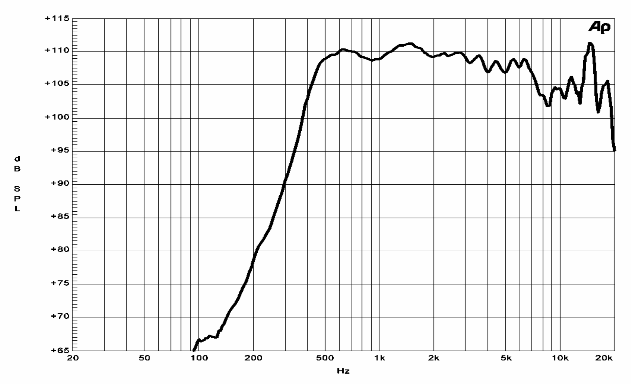
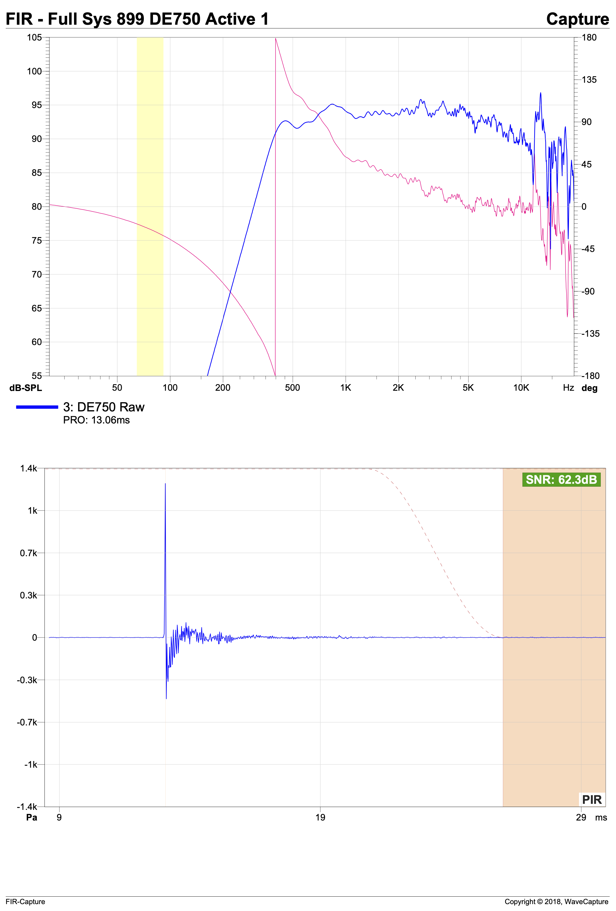
B&C tends to be pretty honest with their specs in my limited experience. Here's a screenshot of the magnitude response using their ME75 90x40 horn from the B&C brochure: Here's an outdoor reflection-free measurement I made of the DE750 on the Tractrix horn. This is with no processing and no smoothing. The B&C brochure nailed it. My measurement shows lower SPL mainly because it was made at 15 ft. The DE750 has got to be one of the easiest compression drivers in the world to EQ. I know you're after a 3-way system, but I'm after a 2-way and this may be the end game. TBD. God bless you and your precious family - Langston
-
I completely agree. I expected the B&C DE750 (on the Dave Harris Tractrix) to result in an unnatural midrange due to the metal diaphragm, but was surprised by the opposite. Openness, clarity, fatigue-free even at stupid volumes. When I'm biased against something and it turns out to be great, or vice-versa, that's pretty convincing subjectively. I tested it as the top part of a Klipschorn two-way. Bass horn 6th order LR 400Hz (acoustic) low pass, DE750 6th order LR 500Hz (acoustic) high pass 7dB lower than LF passband, active, time aligned at crossover using outdoor ground-plane reflection-free measurements. I also tried the Faital Pro HF206 and expected better results, but while it was very, very good, it was short of the openness, clarity and dynamic ease of the DE750 using the same setup (completely different processing, but same acoustic results). It was interesting to see virtually identical unprocessed LF rolloffs on both the HF206 and DE750 with the Tractrix horn, obviously dictated by the horn. About a week ago I got the B&C DCX464, ME464 horn and Eminence 2 inch adapter for the Tractrix horn that @Wirrunna is using, but haven't had the weather needed to do the measurements. Rain, heat, rain, heat, ugh. Impedance is dead-on and indoor nearfield acoustic measurements prove the drivers are proper. Maybe tonight.. Once I figure out what I like best, inverse filtering (FIR) will be involved, but for now I'm putting everything on an even footing so I can hear what they sound like on their own. God bless you and your precious family - Langston PS: Beautiful work @Ol_mcdonald !
-
Third picture on this eBay sale should do the trick: https://www.ebay.com/itm/373556503304 God bless you and your precious family - Langston
-
Thanks so much - sorry I misunderstood. : ) I was starting to annoy myself for pushing this thing so far and thought maybe I was posting too much about it. It's my first real attempt to understand the inductor, tapped or not. Plugging stuff into software and designing crossovers is easy, but I wanted an intuitive grasp of what was going on. I won't be surprised if what I learn leads me back to the active stuff I've been doing for years, but I hope not. I joined the forum recently to learn about this and the strange triangular loudspeaker that goes in the corner - like the bad kid in school. I've received this in spades and really appreciate it. : )
-
: ))
-
That is a fact. My stomach turned when I wrote that. Input and output power are almost equal with the autotransformer vs. a resistor L-Pad where power is dissipated to ground. And you're right - the swamping resistor is an expense - an expense I'm more than willing to pay given what I get out of it. Re: the Chief, I'd love to meet you - but I don't have the patience for fishing. Let me know if I'm a problem and I'll disappear. At this moment I'm half way through a Crosby Stills and Nash album using the Klipschorn as intended as a 3-way (triamplified), and cheating further with the Crites A-55-G/K-400 and DE120 Dave Harris Tractrix. Very nice, but falls short of the two 2-ways (biamplified) I've tried the last two weeks, even at low levels. At higher levels It can't flesh out the lower frequency meat that the 2 inch drivers deliver even though the crossover points are identical. L/R location is much more toward the loudspeakers, whereas the two 2 inch / Harris Tractrix 2-way setups I've tried result in the loudspeakers largely disappearing. Nevertheless I could easily live with this "classical" 3-way system. The ear/brain system adapts. "Helplessly Hoping" just started. Phenomenal. : ) God bless you and your precious family - Langston
-
Sure enough, the battery on the (calibrated) Keysight U1733U was dead when I tried to use it for a second go at it. The new battery made the results quite different, which has been edited in the post. Apparently it has to source a fair amount of current to make larger inductance measurements. The Audio Precision measurements don't rely on batteries. : ) Thanks! - Langston
-
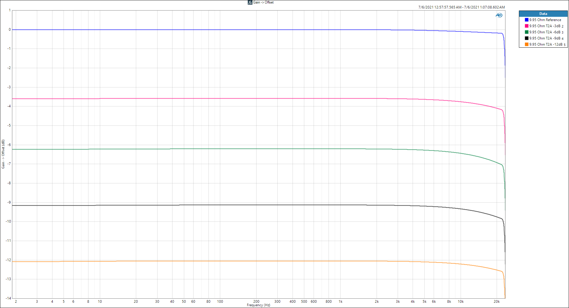
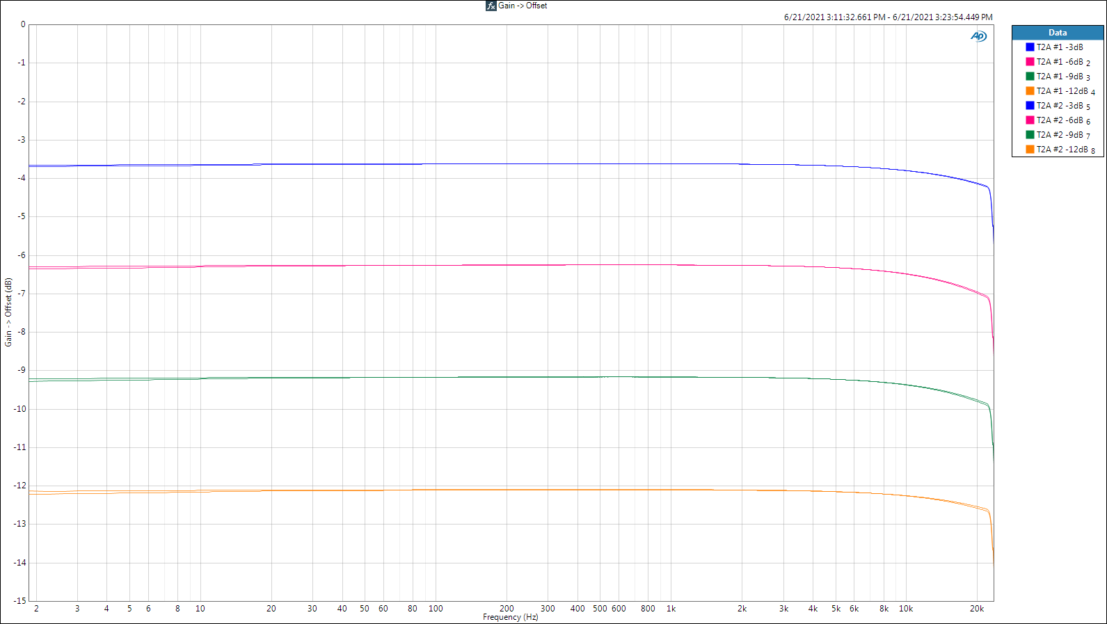
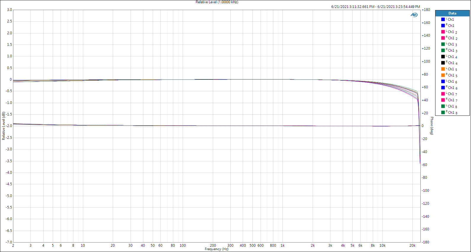
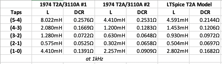
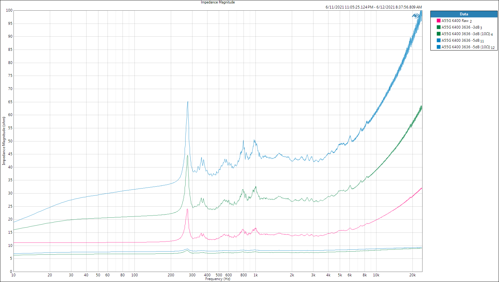
Well, then, might as well finish by measuring the T2A a bit more. Universal Transformer knows what they're doing. Here's a screenshot of the tap to tap measurements of my pair of T2A's as well as the data from the LTSpice file that Mike gave us. There's a lot of difference between samples.. Or is there? : ) T2A L DCR.xlsx Since these things are basically L-Pads using inductors1, it isn't inter-tap absolute values that have to match, what has to match are the ratios between them because that's what causes the gain reduction. And these ratios match nicely. PWK did not compromise his life's work with the autotransformer. Small signal measurements of my pair of T2A's at each attenuation step with a 10Ω load in place of a driver. Now I take all (8) measurements and force the magnitude traces to intersect at 1kHz to see the overall variation between every setting of each AX. Phase is also shown, but it is not normalized. I've seen worse, but not from an autotransformer. : ) God bless you and your precious family - Langston 1 Nope, it ain't. An AX is a continuous winding on one core with one or more taps into those windings with its behavior determined by the ratio of turns or voltage or current, depending on how you want to measure it. I'm learning. : )
-
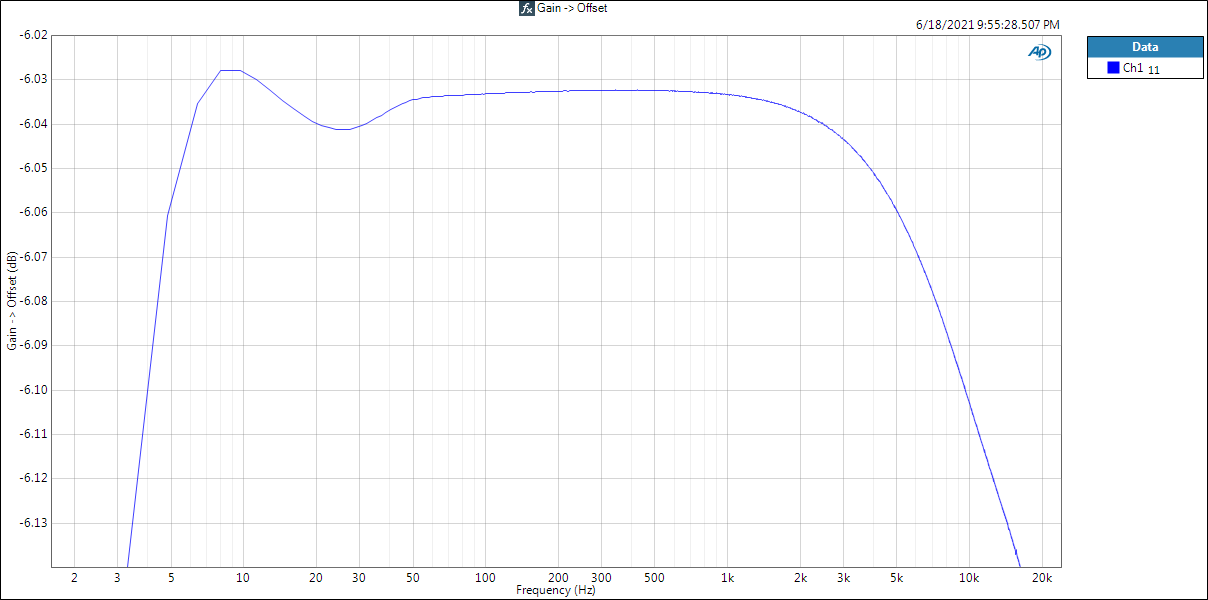
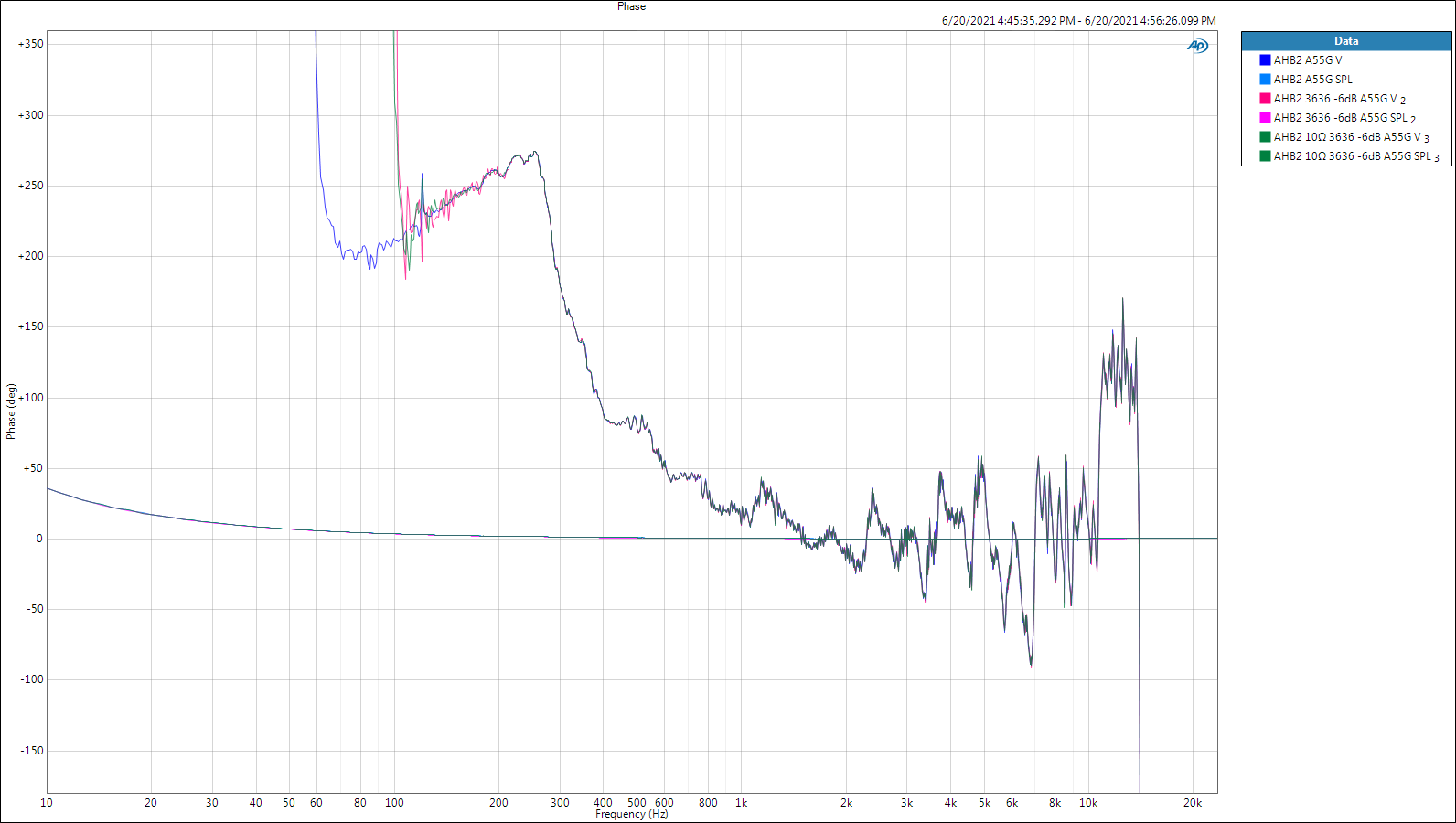
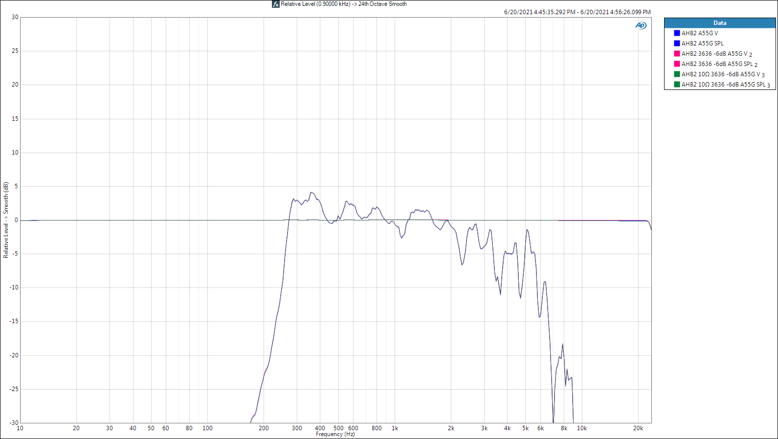
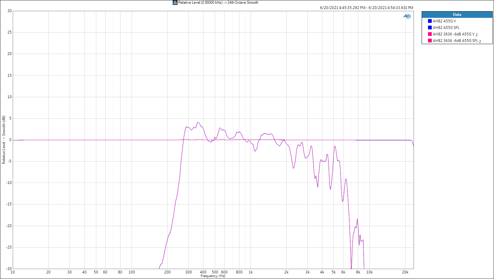
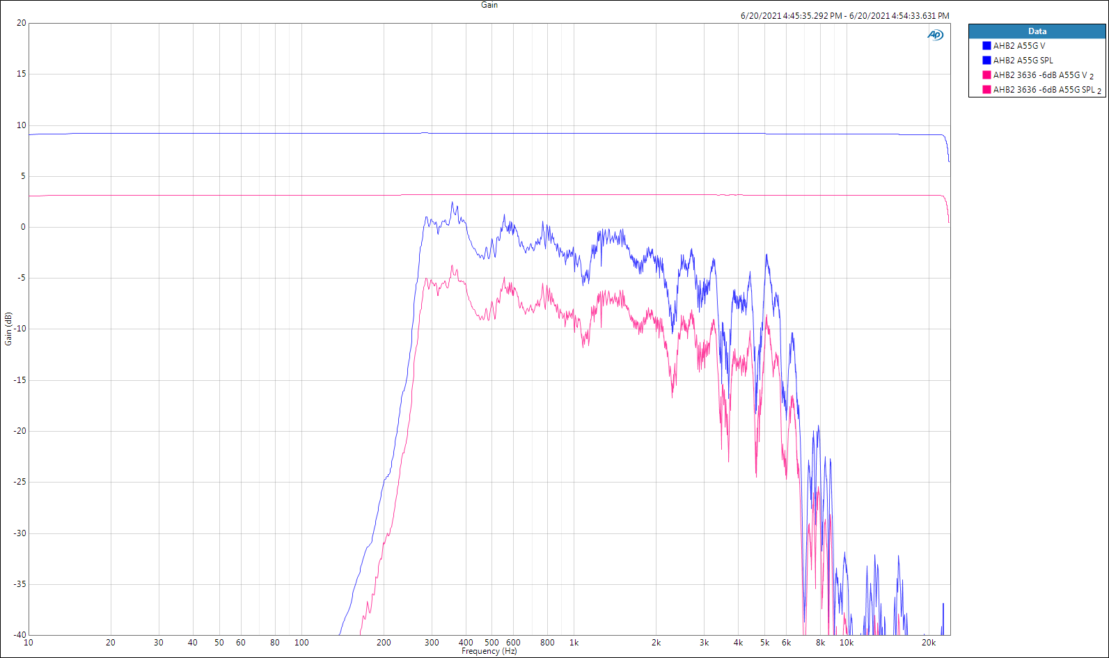
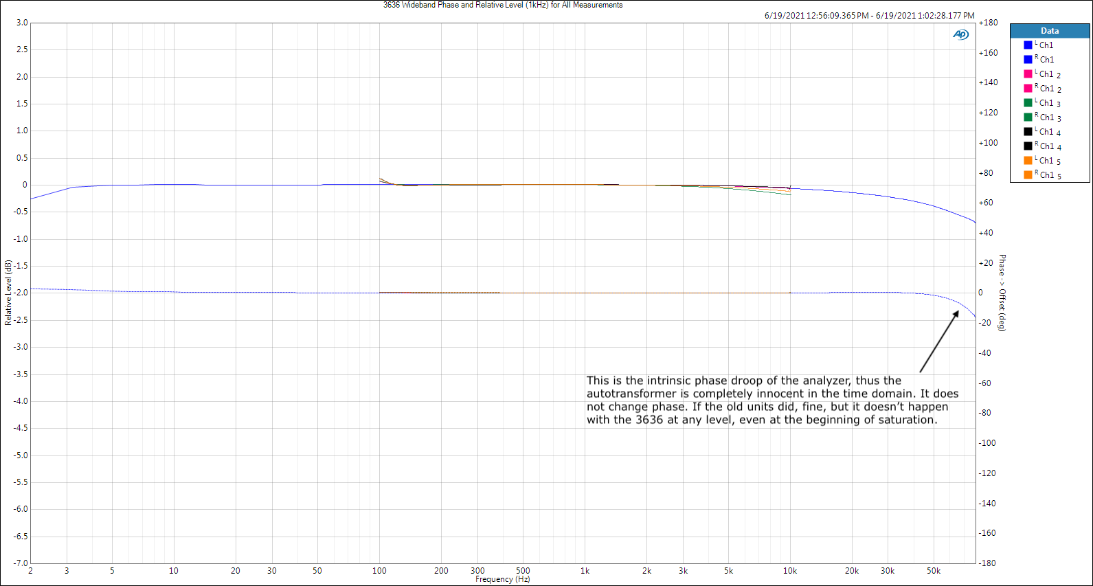
Thanks Mike for the 3636 and T2A LTSpice component files. As you know LTSpice assumes ideal components, but also allows the addition of parallel and series L/C/R values to make the model act like the real thing. I measured a 3636 sample and got slightly different inductance and resistance values between taps than you did, but both models missed real measurements too much for my taste. I've attached my version of the 3636 component file that you can use to get my inter-tap values. Crites 3636.asc Still, the only reason to bother with such an exercise is if you don't use a swamping resistor on the input of the AX. With a 10Ω resistor across the AX inputs, the specific AX impedances become useless information because the resistor overwhelms everything downstream of it. The resistor is Borg - it assimilates everything - but in this case inductance becomes futile, not resistance! : ) So back to the real world that I know and trust - measurement. I decided to measure the voltage applied to the A-55-G driver input terminals simultaneously with the nearfield acoustic output from the K-400 horn (mic almost touching the grill cloth). Dean asked for the -3dB (0-4) attenuation setting, but I decided to use -6dB (0-3) to make transfer function defects, if any, more apparent. I don't include a series capacitor in this group of measurements because it would make things too busy. Next time. It doesn't reveal anything IMO. Conclusion: The 3636 is transparent at audio frequencies. All it does is reduce voltage like a volume control by the amount selected without messing with the time domain (phase, etc.). The max output of the 3636 decreases as attenuation increases, the specifics of which were shown here. Blue traces are the reference measurement without the 3636, i.e. with the amp directly connected to the driver. Pink traces add the 3636 set at -6dB between amp and driver without a swamping resistor. Again, each measurement includes two traces of the same color for the electrical input and acoustic output of the driver. Now what I've done is take those same traces and force each to intersect at a mid-point (I chose 900Hz). I also smoothed the curves to 24th octave. This makes it much easier to see if the frequency response varies when the 3636 is inserted in the circuit. Next is the identical plot except this time I include a third pair of (Green) traces that add a 10Ω swamping resistor on the input (0-5) of the 3636. Now the final nail in the coffin to dispel the AX phase error myth. Again, all three pairs of traces are shown. God bless you and your precious family - Langston
-
Never! I'm only two weeks old with the Klipschorn. If Roy keeps the stunning bass slam of the Klipschorn while increasing LF extension with those ports, I'm going to rob a bank. Simple as that. Also, down here in the South it's considered bad manners to ask something like that without the possibility of a solution. Is there a pair setup somewhere in the US in a proper room where the room modes have been dealt with at the listening position? : ) Also: I haven't done the tuning for my 1 inch A-55-G/K-400 and DE120/Dave Harris Tractrix horn yet, so I haven't heard the Klipschorn as designed, well as a highly modified 3-way I should say. I never used the OEM woofers other than measuring their TS parameters (they're in good shape) - I installed the Crites cast frame woofers. Silly little 15 inch things with a tiny 150W rating (I'm used to pro audio) that almost knocked me on the floor. Those corner horns are brilliant. As of now I've only listened to the system as a two-way with Dave Harris' large wood Tractrix horn with the Faital Pro HF206 and B&C DE750. I also just got the B&C DCX464 with the big horn they made for it, but haven't even done the raw measurements on it yet. I assume that'll be the winner, but I've been wrong so many times. This is also taking longer than expected because everybody I know is coming over to hear the Klipschorns.
-
You're absolutely right! The autotransformer would do just that and each tap would present yet a different inductance (one of the three parts of impedance) to the passive network that is loaded by the AX/driver combination. Thus different caps, etc., will have to be used due to the AX and changed again every time you choose different attenuation taps. Unless.. .. you use a swamping resistor and turn the AX/driver system into a resistor that barely changes value even as you change taps. Then who cares about the AX and driver with all their weird internal inductance/capacitance/resistance when all the passive network sees is what it thinks is a very close approximation to a constant value resistor? I wouldn't consider dealing with a moving target to load my passive network, thus it's AX plus swamping resistor or no AX for me. This plot illustrates what I'm saying - and please forgive me if I'm missing your point! And I'm still going to do those measurements you and Dean mentioned. : ) God bless you and your precious family - Langston
-
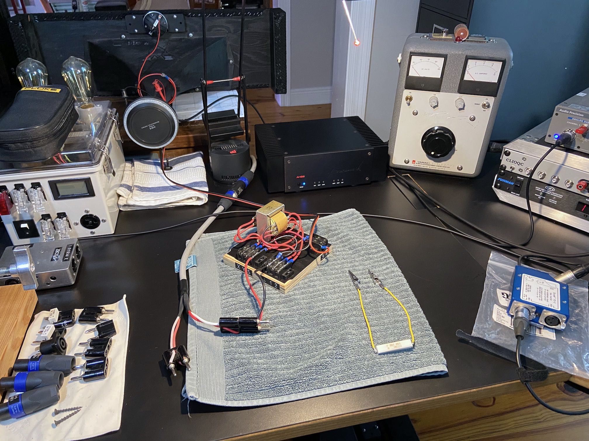
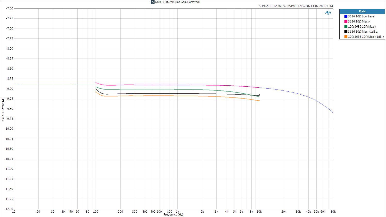
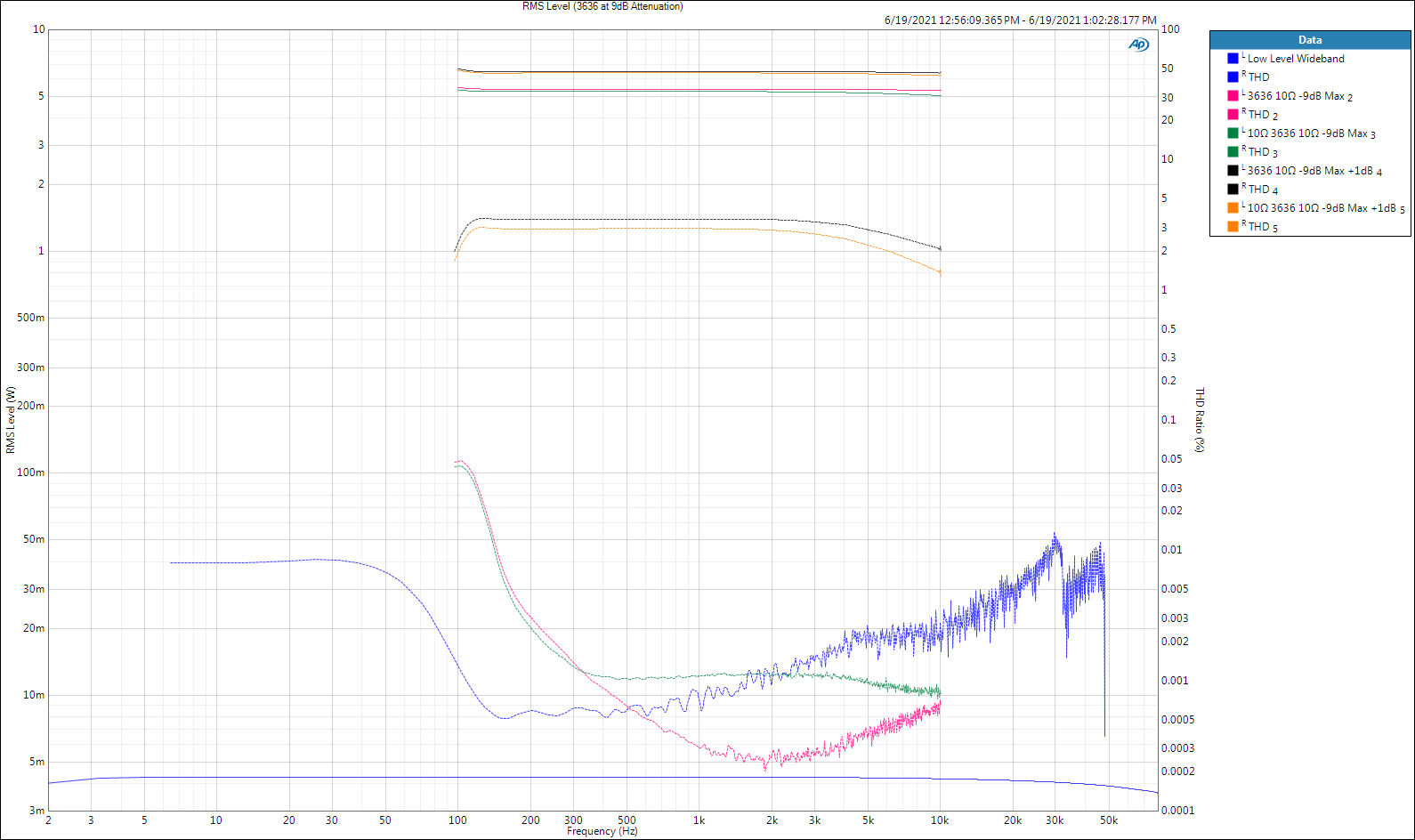
Alright you whippersnapper, I re-ran the measurements again this morning, but only at the -9dB step on the 3636 so I could demonstrate a couple of other things. The measurement setup: APx515 output -> AHB2 (bridged, more power Scotty!) -> 3636 (0-5, 0-2 taps; -9dB) -> 10Ω 10W resistor across 0-2 output taps -> APx515 input. Notes: Adding a second 10Ω 10W resistor across 0-5 input taps slightly reduces distortion in the 3636 simply because it received slightly less voltage. The swamping resistor did increase distortion slightly in the amp due to the increased load. Thus I chose to skip the swamping resistor for all measurements until this post. The swamping resistor in parallel with the 3636's input also caused a slight increase in HF rolloff; immaterial in this application. I have (6) samples of the 3636, (2) made in 2016 (yellow tape), (4) made last month (white tape). They all measure virtually identically, thus I just used one installed in a jig for all measurements. The following Max Output plot was done entirely at the -9dB tap setting and adds measurements with the swamping resistor and 1dB into saturation (about 3% THD). Next zooms into the attenuation provided by the 3636 at each of the above drive levels and bandwidths. And a final effort to put a nail in the coffin of the autotransformer phase error myth. Options: 1. If you really want autotransformer behavior in your passive crossover and need more than 8dB attenuation, use a pair of inductors in an L-Pad type arrangement that can deliver the power you need to the driver without saturating. You loose adjustability but you retain the other benefits. 2. If you want to use the 3636 and need more than 8dB attenuation, use an active 2nd order (adjustable Q) shelving filter to reduce the passband further. There's another benefit to this in that near the crossover from low to mid/high, the shelving filter will also be pushing the nasty bass horn resonances further down. 3. Don't attenuate anything passively, skip passive impedance compensation, and don't use the passive network for any kind of EQ whatsoever. Design the passive network for proper high and low pass function alone, then use active filtering to do everything else. This will give you almost all the benefits of bi/triamplification while still being able to use a single (low output impedance) amplifier. Of course the loudspeaker will be useless without the active processing, like the new Jubilee. I stole this idea from the great Dave Gunness and used it extensively in concert production. Cut my amp racks approx. in half. 4. Be a sissy and use resistors. 5. Stop the insanity and go fully active, like the new Jubilee. Active will probably be cheaper by the time I'm done and may very well be what I end up with, but I wouldn't have learned anything. PS: I've been cheating the whole time I've been writing these posts and using fully active DSP bi/triamplification to design and tune my Klipschorns. Once I decide on the endgame for the top hat, I'm hoping for a passive solution with flat impedance around 6Ω from 40Hz to 20kHz. The Klipschorn is the most exciting loudspeaker system I've ever heard in my life. I always thought this was possible, but not until a couple of weeks ago did I experience it. God bless you and your precious family - Langston
-
Spot on. I was wondering if someone would point this out. : ) 2.7W in dB is 10log(2.7) = 4.3dB that you add to the 110dB sensitivity for 114.3dB maximum peaks. That's loud, but for midrange peaks I'm aiming for at least 120dB. The orchestral stuff I like most hovers around 20dB or more crest factor (peak to RMS), which means I'm in the upper 90's (loud as heck) RMS. I go there sometimes. It's also a little rude to pony up for a pair of drivers like that and adjust their effective max. wattage rating down to 2.7W. : ) God bless you and your precious family - Langston