Langston
-
Posts
148 -
Joined
-
Last visited
Content Type
Forums
Events
Gallery
Everything posted by Langston
-
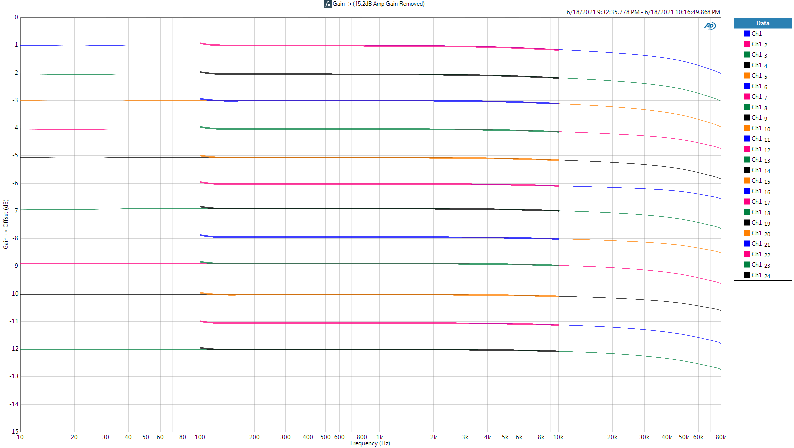
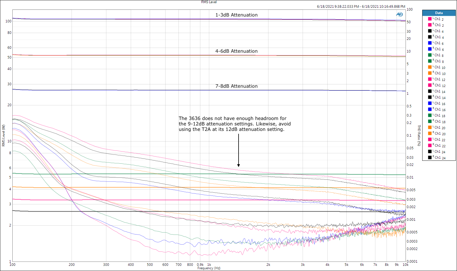
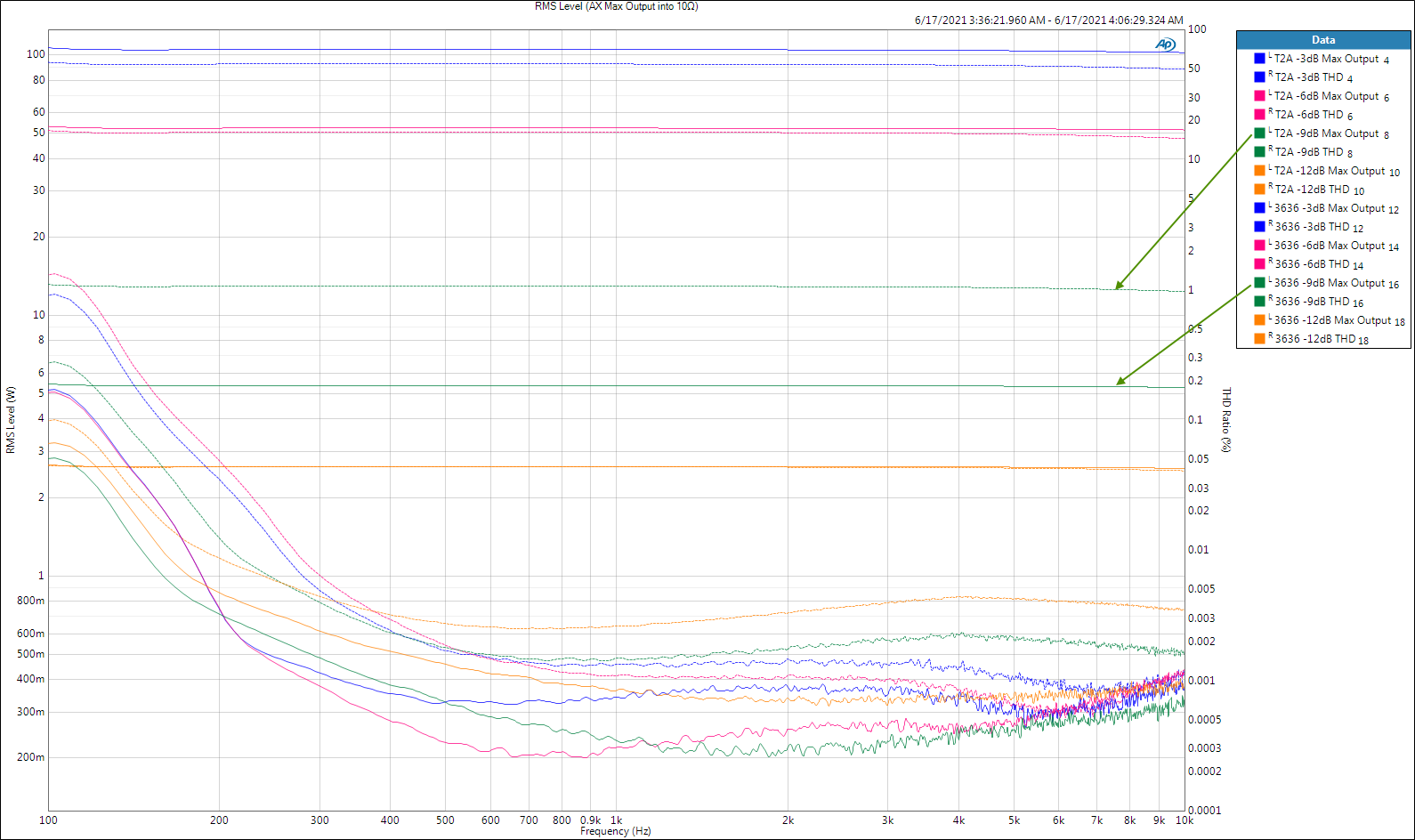
Third measurement group: Transfer function analysis. (Addendum) We found out from my previous post's Max Output plot that both the 3636 and T2A have attenuation settings (taps) that shouldn't be there. The 3636's -9dB (5.4W) and -12dB (2.7W) taps are unusable due to the very low output available before clipping (saturation). The T2A's -12dB tap shares the same 2.7W clipping threshold. If I didn't err in my measurements, the 3636 is unusable from -9dB to -12dB and the T2A is unusable at -12dB. Because I'm so interested in using the 3636 in my passive crossover designs I went back and performed all the measurements again, and this time I measured each 1dB step of the 3636. Turns out my prior measurements were correct, but I want to spill the beans on what I learned. Somebody (Universal Transformer or the Crites or both) should have warned us about the 3636 limitation. I suppose it's very rare for anyone to use those things at greater than 8dB attenuation, but the additional taps really shouldn't be there. First, the good news. Each gain step is dead-on. The thick traces from 100Hz to 10kHz are the Max Output measurements. They overlap the low level, wideband measurements because the 3636 (and T2A) attenuations are constant regardless of drive level (within their linear regions). Next is the Max Output (watts into 10Ω) plot at each of the 12 attenuation steps. Finally, I made a cheat sheet for the 3636 that should be helpful. Red is bad. There's a download link for a PDF version below the picture. 3636 Autotransformer.pdf God bless you and your precious family - Langston

-
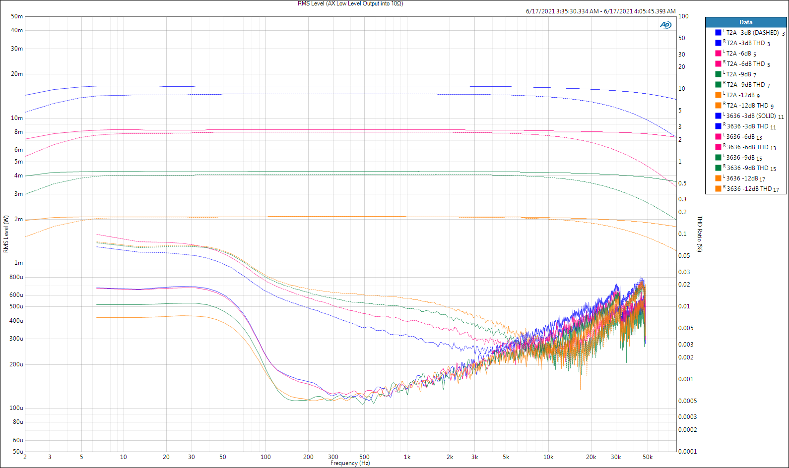
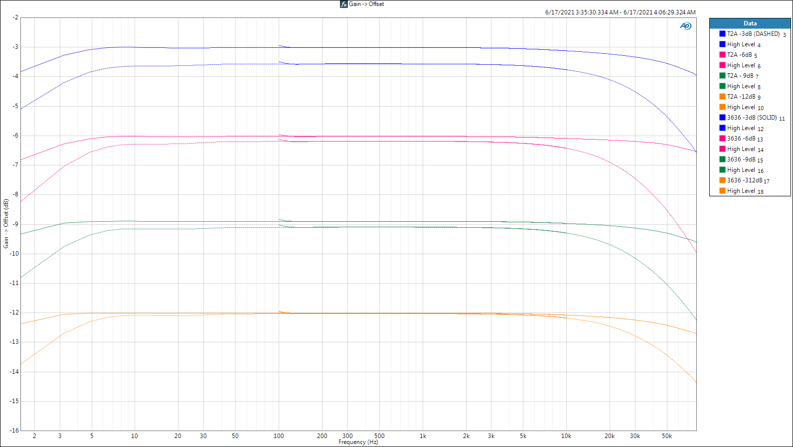
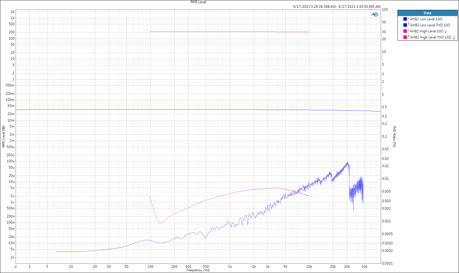
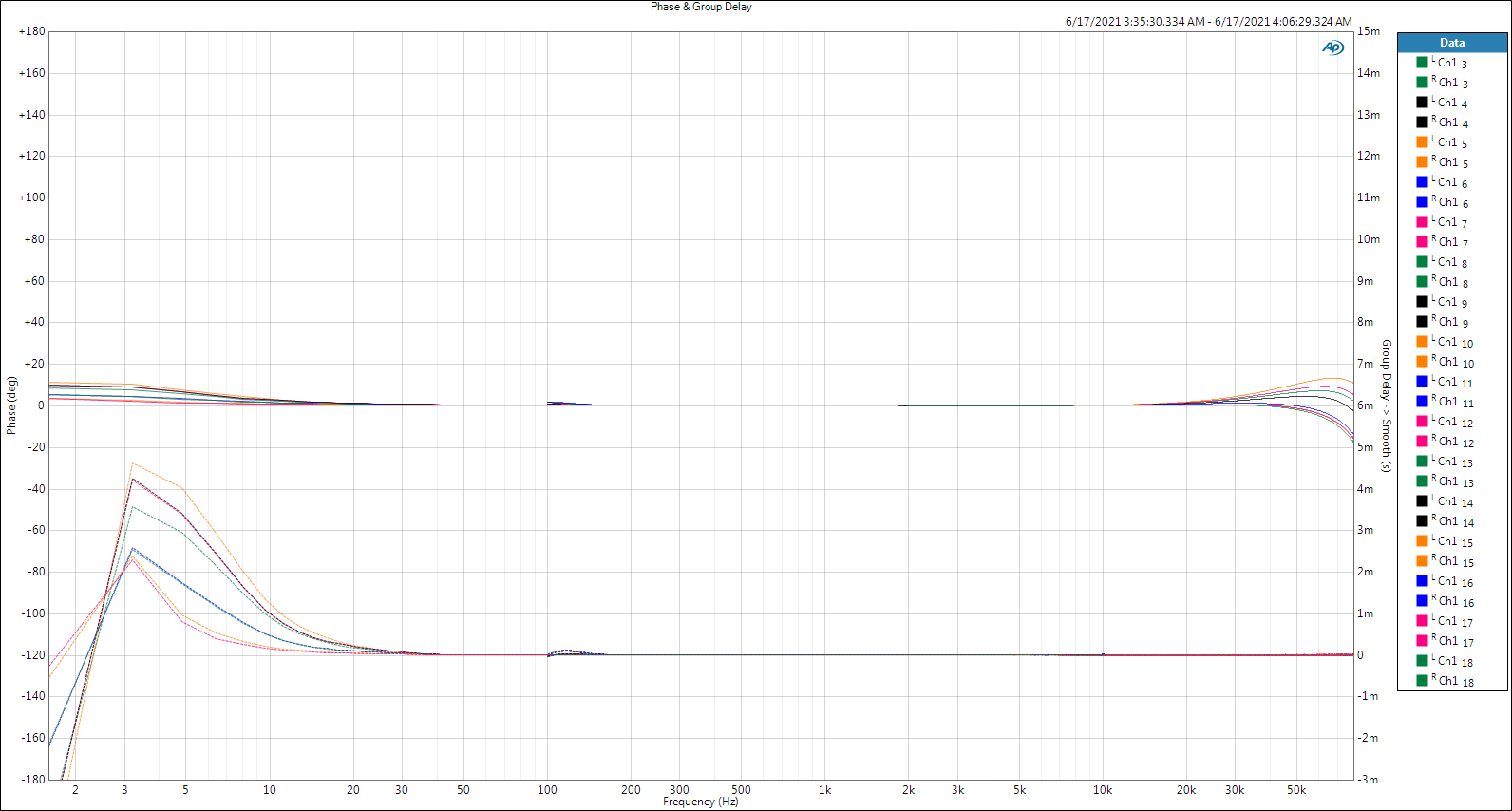
Third measurement group: Transfer function analysis. Since I've already prepared the electrical domain measurements, I'm going to post them here and add a 4th post to cover questions. So far I have (2) from @mboxler and (1) from @Deang. Everyone is invited to fire away with more questions and I'll answer them (with measurements) if I'm able. One of the questions has to do with inductance values of the AX between the 0-3 output. A note on this: I've decided not to try to figure out how to accurately add the AX to my crossover optimization software, instead I include the swamping resistor plus AX in my driver impedance measurements as if the driver came with that stuff built inside of it. The 3636 AX does not change acoustic magnitude or phase, it only applies attenuation, thus no need to include the AX in acoustic measurements (unless you want to do maximum output testing). Thus I avoid screw ups characterizing the AX as a simple pair of inductors in L-Pad configuration, which I assume it is (nope, it's a continuous coil sharing the same core with taps). If someone has successfully modeled an AX in Spice type software such that the predictions proved correct, please let me know. : ) - - - I show two measurements of each AX; the 3636 and a '74 vintage T2A/3110A. The first is low-level, wide bandwidth and the second is the most the AX can handle at a given attenuation level between 100Hz and 10kHz. Even though the 3636 can do 1dB attenuation steps to -12dB, the T2A only has four output taps at -3dB, -6dB, -9dB and -12dB. Thus I decided to measure each AX at those attenuation levels. Every measurement included a 10Ω load resistor across the AX output to simulate a driver. First up is the reference measurement of the AHB2 amp in bridged mode into 10Ω alone. I only took it up to 200W because that was the max that either AX could handle. Next is phase and group delay (which is just another way to look at phase). I include every measurement made just to get it out of the way because both AX units were effectively perfect through the audio range. You'll see a small bump at the beginning of the high level 100Hz-10kHz sweeps. That's due to suddenly hitting the AX inputs with high power. If you happen to do that to your loudspeakers at some point, that little bump will be the least of your worries. Next is low level wide bandwidth output and THD. The dashed traces are the T2A, the solid traces are the 3636 (as on every plot). Next are the maximum outputs at each nominal attenuation setting that remain under 1% THD. I adjusted the generator in 1dB steps. Once the AX exceeded 1%, I dropped the generator level 1dB and recorded that as the max. This wattage level is across the output loaded by 10Ω. To figure out the much higher wattage absorbed by the 10Ω swamping resistor on the input, multiply the -3dB output by 2, -6dB by 4, -9dB by 8 and -12dB by 16! There is a surprise in this one. The T2A for the first time outperforms the 3636 at something. At the -9dB attenuation setting the T2A's max output is as expected, mid level between the -6dB and -12dB settings, but the 3636 is low. It must be a design issue (due to the 1dB steps?) because I got the same results with a 2nd unit that is 3 years newer in mfg. date. It's fine for our use, but it shouldn't do this and I'm going to look into it. Next are the actual attenuations provided at the four nominal level settings. This includes both low and max levels. The 3636 nails it, but the T2A is only off by 0.6dB worst case. God bless you and your precious family - Langston
-
So turn off your air conditioning if you don't want to "waste" power. You'll live. Alone maybe, but you'll live. You buy comfort with that power usage, I'm gonna buy a resistive loudspeaker over the lion's share of its output for the sake of rock solid passive network behavior regardless of voice coil temps and the ability to use tube or constant current amps without having to measure the system and apply inverse EQ to it to flatten it back out AND the ability to change mid/high attenuation levels at will, and driving the system with a single amplifier. Cranky soldermeister indeed! : ) BTW, thanks for the suggestions for other measurements. I also genuinely enjoy and learn from your posts - it's hard to interpret weird people's writing like my own at times, thus I'm stating that for the record. : )
-
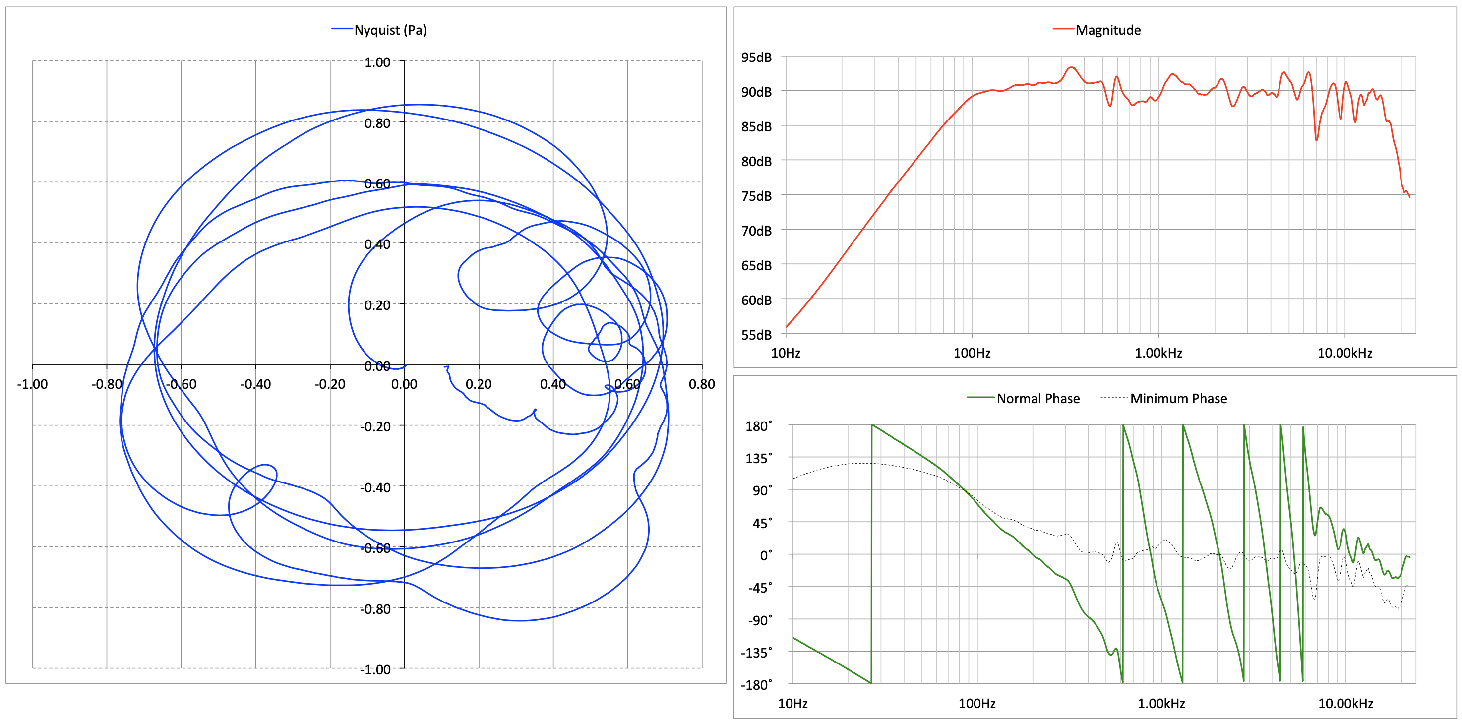
So true. Dick Heyser was a huge fan of the Nyquist plot and I'm a huge fan of his, so I tried and tried to learn to love it, but me and the rest of the pro audio world pretty much let it die out with the TEF analyzer. Still, you can see stuff in it that isn't apparent with any other plot and if you work at it you can ignore many traditional plots and rely on the Nyquist. For example, the horizontal axis (real) is SPL (presented in pressure units above), the vertical axis (imaginary) is - wait for it! - the VELOCITY of the sound. That is so cool because sound only moves air particles back and forth, the speed of which increases with frequency. Thus, high frequencies move the air particles quicker, which takes more energy, thus when you are a good distance from a concert venue, only the low frequencies remain. The mass of the air molecules damped out all the highs. Sound PRESSURE on the other hand travels the distance from source to receiver. Just like a wave in the ocean that travels hundreds of miles, the actual water stays where it is - the water just bobs up and down as it passes - the distance between crest and trough is the loudness or SPL of the wave and the amount of time it takes is frequency. The Nyquist pressure is also a circular plot of the impulse response! And you can see magnitude and phase in there - but you have to think 90˚ (Hilbert transform-like). You can see all that stuff in the Nyquist and a heck of a lot more, BUT it's hard to apply much of it to the stuff we do. Thus the lack of interest. : ) God bless you and your precious family - Langston
-
I have a pair of '86 vintage Heresy II's that still work perfectly in spite of the dried out looking woofers. They are a study on how much phase rotation we can put up with and still have amazingly good sound. Mine disappear under 90Hz or so, thus wall or corner placement can help a lot. I'm going to read that Super Heresy 1.0 thread. : ) This is an Excel based presentation of the Heresy II's transfer function back when I was playing around with Nyquist plots: God bless you and your precious family - Langston
-
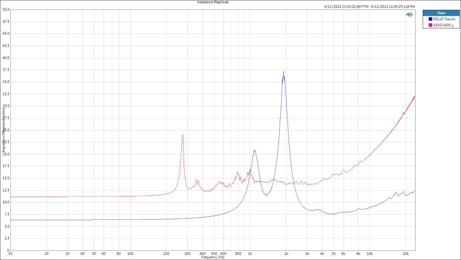
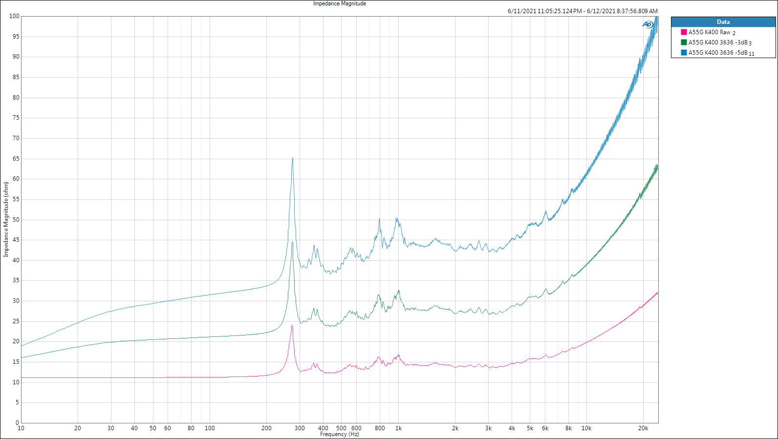
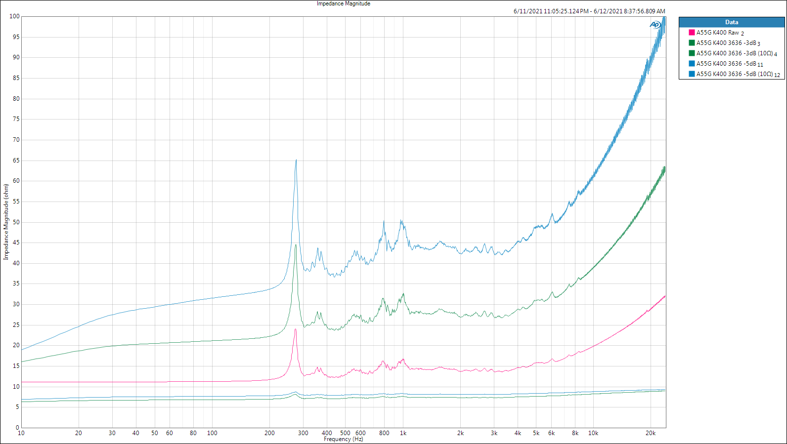
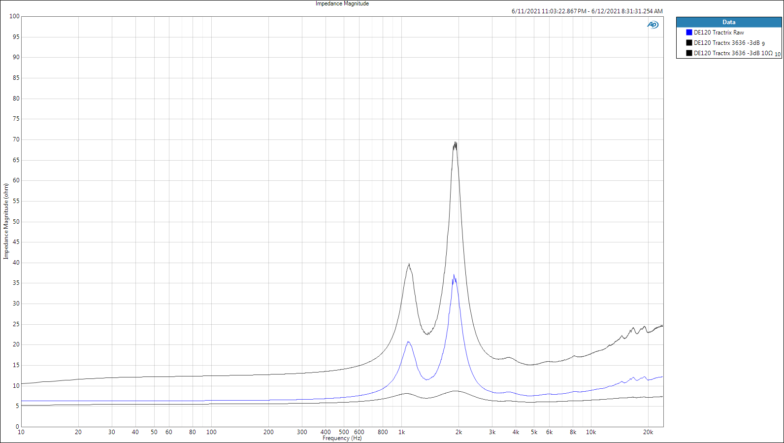
Second measurement group: The autotransformer's impedance effect. With passive crossovers and horns, significant mid/high frequency attenuation relative to the low frequency passband is required. My taste at present for the Klipschorn is about 7dB less mid/high output after equalizing for room acoustics under 200Hz or so. Before playing bop-a-mole with the room modes, I needed a 10-11dB mid/high reduction for balance but the bass quality remained unacceptable, of course. The two huge benefits of the AX over resistive pads are the ability to change mid/high attenuation without screwing up crossover response (when used with a swamping resistor), and immunity from voice coil temperature changes. Both benefits result from the AX's presentation of a constant impedance to the passive crossover network. This also allows simpler crossover design (imagine building a network for an 8Ω resistor) and the ability to use any genre of amplifier without tonal changes. Downsides? Phase? Group delay? Inductance? Distortion? Frequency response? That's coming up in the third measurement group. Very helpful post by @henry4841 on the AX background, thank you. I am a newbie at home audio and it's turning out to be as hard to get right as professional audio - maybe harder. I thought it might be boring at first and so far it's kicking my butt. Thanks also to @mboxler for the series capacitor idea - will do, but given that I'd lose most of the impedance compensation benefits without a swamping resistor, it too will be part of the setup. Without the swamping resistor the AX doesn't interest me. The first of several iterations to my '74 Klipschorn top hats used a Crites sourced DE120 high frequency driver with their horn and A-55-G mid frequency driver for the existing K-400 horn. The latter was a big improvement across the board, but the little horn provided with the DE120 resulted in a rough rolloff right around the crossover frequency, thus I got Dave Harris's (Fastlane Audio) drop-in wood Tractrix horn and the DE120 became nearly flat down to 1kHz with a rolloff that looked just like the B&C literature. Brilliant. The following impedance measurements use these two driver/horn combinations without any passive components other than the 3636 AX and a 10Ω swamping resistor across its input. Raw measurements of the DE120/Fastlane Tractrix and A-55-G/K-400: The A-55-G/K-400 adding the 3636 at -3dB and -5dB attenuations: The same, but this time with the magic swamping resistor: Finally, the DE120/Fastlane Tractrix and 3636 at -3dB with and without swamping resistor: God bless you and your precious family - Langston
-
You're right - this forum attracted me largely due to that fact. I should have said that in reference to the thread @RandyH001 pointed me to, that's what I was thinking about. Anyway, I'd love to hear about the lunch expenses. So far it's looking like a cost issue alone - I'm really impressed with this gizmo. Other than the ≈35Hz impedance bump in the Klipschorn, the autotransformer will allow a virtually resistive load to 20kHz. That would be a huge plus for tube amps and other higher output impedance amps. Zobel type networks are a partial solution, but like any other part of a passive network they're dependent on load impedance and when that changes (driver voice coil heating), it changes. The autotransformer just doesn't care. Apparently. TBD. : ) God bless you and your precious family - Langston
-
That was the funniest thread I've read in a very long time. I don't understand the zip tie thing, but I can guess it's related to duct tape, which is related to.. Nevermind, I'll look it up.. Well, maybe not. : ) My purpose in this thread is identical to the inductor thread, my walk from ignorance to somewhere else sans preconceptions as much as possible. I stole the PWK article link from one of Bob Crites' posts - I'd stolen it from you if I'd seen it earlier! There's so much talk and so little measurement around here. : ) God bless you and your precious family - Langston One accurate measurement is worth a thousand expert opinions. - Grace Hopper
-
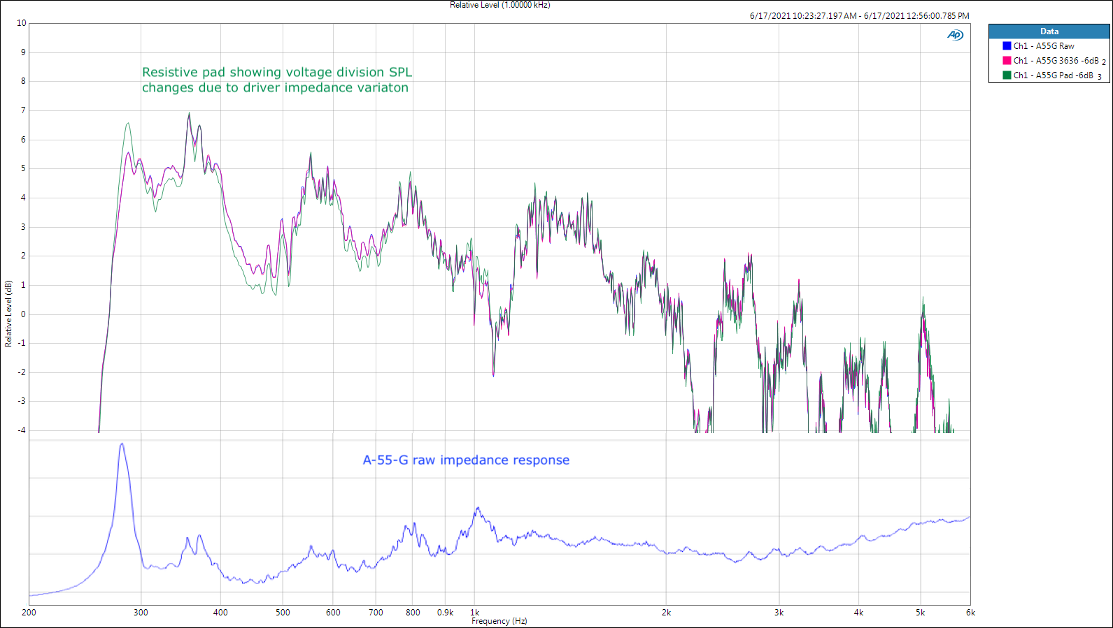
First measurement group: PWK's autotransformer experiment, revised. The GREEN measurement traces are the -6dB resistive pad setup. The BLUE traces are the raw driver/horn and RED traces are the 3636 AX setup for 6dB gain reduction. I've included THD at this low drive level, but there's nothing to see there, both gain reduction methods were the same. You'll notice a ±0.5dB departure of the GREEN resistive pad trace relative to the RED AX trace, but the departure is lock step with the driver impedance curve (second plot), thus a result of voltage division - not electrical damping. The A-55-G driver has a very smooth impedance curve, thus the voltage division induced SPL variations are slight. In PWK's case, his driver/horn probably had impedance peaks at 1.5kHz and 2kHz, thus the apparent "ringing" of the driver was actually caused by increased voltage being supplied to the driver, not a reduction in electrical damping. Now you can shoot me. : ) God bless you and your precious family - Langston
-
Moving on from inductors in my insane pursuit of a passive crossover that is audibly indistinguishable from active, I turned my attention toward mid/high frequency gain reduction that horn loaded systems can't live without. About 6 months before I was born, PWK published this paper supporting his use of auto-(Greek for self or one)-transformers instead of resistor pads. Automatic transmissions and washing machines! What will they think of next?! : ) The autotransformer (AX) route is interesting in part because it's WAY more expensive than a resistor - so why suffer the expense when they worked so hard to cut costs in every conceivable way to survive in the market? There must have been some choice words to PWK from whoever kept the books back then... Be thankful that the engineer won this one. From my measurements, a well made AX behaves almost identically to active gain control, while the voltage division provided by resistors do not and can not. Is the difference audible? Probably not. IF you drive the loudspeaker at very low levels so the voice coil remains cool enough not to increase its impedance. PWK's article claimed two AX advantages: 1. They allow user adjustable gain changes without screwing up crossover behavior. 2. They reduce series resistance from the amp to the driver, thus improving electrical damping with measurable improvement in the acoustic domain. Claim #1: Is true and false. Is not true unless you parallel a 10Ω (or thereabouts) resistor across the input of the AX, as recommended by @Al Klappenberger and others. The problem with this is that the lower impedance seen by the crossover will increase costs (larger caps) to maintain the same high pass behavior. Maybe the guy that kept the books won this round. The great news is that this isn't a problem for us and we can use a 10Ω "swamping" resistor to give us a nearly flat 7Ω compression driver - thus claim #1 is fulfilled! BTW, you can't just add the resistor - you'll need to redesign the crossover, after which you'll be able to adjust AX gain reduction at will without compromising crossover behavior. Claim #2: Is true and false. It is true that the AX results in almost zero added series impedance to the driver, and not just because of low DCR, but the electrical impedance transformation (the greater the gain reduction selected, the lower the impedance the driver sees). Remember this is an AC circuit. The swamping resistor improves things a bit more. BUT does this increase in electrical damping really make a difference to a horn loaded driver that gets the majority of its damping through acoustic impedance? BTW, acoustic impedance is the reason to fall in love with horns if you haven't already. PWK's paper shows a measurement from an experiment he did in a shootout between the AX and a resistor based pad. I repeated the experiment this morning. For the most part. Unfortunately, PWK did not provide full details of his measurement setup, but he did employ a two different passive crossovers, one designed for the AX (values shown) and the other for the resistive pad (values not shown1). I don't like the smell of that and prefer to hold all variables constant excepting, in this case, the gain reduction method. Even if PWK had revealed all crossover components used, the stuff available today wouldn't be the same, thus it's impossible to recreate his experiment exactly, which is fine with me as I already implied. The other items that aren't available to me are the driver/horn combination and AX model he used, but what I used instead is more relevant to us - a Crites A-55-G on a K-400 horn with the Crites 3636 AX. The quality of this setup and the possibly additional acoustic impedance of my '74 vintage horn could be the reason I saw no improvement I could attribute to the higher electrical damping of the AX method. Thus I'll assume PWK's setup used a lower quality (by today's standards) driver/horn/AX system than my stuff and as a result, the significantly higher electrical damping that played a role in reducing driver ringing for him, didn't help in my system. All is not lost, the AX remains a superior method of passive gain reduction for additional reasons that'll be shown later. My measurement setup used a 14.7Ω series resistance that resulted in a mid-passband 6dB SPL reduction from the driver/horn system. The 3636 AX -6dB gain setting nailed that SPL reduction exactly (0-5 input, 0-3 output). Is it ringing yet? Where's the meat? In the 3636 of course. From an email exchange with Bob Crites about the 3636: On 30, Dec, 2016, at 3:14 PM, Bob Crites <...> wrote: When I had the autotransformers made, I went to the same place that built them for Klipsch. I just asked if there were any improvements they could suggest over how they made them for Klipsch, I was told that Klipsch had them sized for a maximum continuous rating of 40 watts. That saved them a buck or so each compared to the standard 100 watt rating. So I just told them to make them as good as they know how to make them and rated at the 100 watts. I am a fanboy of the Crites. Bob was a gentle member of the No BS club. Salt what I say about them as you wish, but (proper) measurements don't lie (includes the T2A) in another post. I'm planning on three: My version of PWK's experiment, an impedance analysis attached to a driver/horn system and a transfer function analysis that includes wideband low-level and max. wattage, both into 10Ω. God bless you and your precious family - Langston - - - 1 I think. If he used the same crossover for both the AX and resistor pad, then the rising output at the impedance resonance would have been a simple voltage division thing, not a damping thing - a kind of variable EQ due to the high source impedance of the resistor pad. I would love to get yelled at by PWK about this - maybe somebody at Klipsch will put me straight. : )
-
I'm open-minded about that and seriously hope that class D can approach "straight wire with gain" territory, it's just that I haven't heard it do so yet. Class A was off limits to me until the Klipschorn, which is so efficient that anything will do power wise. I have a feeling that John Siau chose switching power supplies for performance reasons vs. economic, but I'm a fan-boy and might be wrong. Here's what he wrote about it. God bless you and your precious family - Langston
-
I'm hesitant about subjective impressions of stuff because humans are all over the map on this kind of thing depending on background and disposition. On the latter I'm all about Galileo's scientific method - but I also fell in love with Dave Brubeck's Take Five album when my Dad played the record on our living room entertainment system in 1963 when I was four. It stunned me and though my career was mostly in finance, science and teaching - Brubeck haunted me. So just after the year 2k I decided that I had enough loot to do something stupid, so I started a concert production company from scratch with the goal to provide the highest possible sound quality even if I lost money in the process. Unfortunately it succeeded and I kept at it until a couple of years ago. I'd achieved what I wanted - a clientele that would pay for my very best effort. The icing on the cake was the oldest and most talented of Dave Brubeck's kids, Chris, used me when he did stuff in the area I covered. Yes I'm bragging. Chris writes symphonies that are usually thematic, such as an Ansel Adams piece with full orchestra and a huge screen fading in and out of different pictures of that amazing black and white photographer while the music did interpretations. It was breathtaking. Other events were more like his Dad's stuff, but still orchestra was involved - jazz band in the middle of the pit that I'd shield with plexiglass and absorbers that had to stay low so everyone could see the muso's - yet it had to work. So Chris Brubeck and I would sit at a center location a few rows back from the stage and mix the event. I had an iPad that was connected to my CL5 (Yamaha) console that allowed me as much control as I wanted for up to 64 channels. And Chris would say something like "a bit more from the winds", or more often "timpani! more!" and I'd do that and he'd smile to the moon. That four year old inside me actually pulled it off. : ) Now what to do? Home audio. Yet I'm still hesitant and my answer may not be very helpful: Amps I have and am familiar with are McIntosh MC275 CE (restored with the best stuff I could find, noise is lower, power higher than specs), Mark Levinson 532H, Benchmark AHB2, and a bunch of professional stuff left over from the business, the only one that sounds really good is a German Camco Vortex 6, second best was the Yamaha TXn series, then all the class D stuff that I've yet to find acceptable from anyone for any other purpose than subs. Well designed solid state rules. You can hear the reverb of the room in good recordings, subtle stuff is all there IF the loudspeakers are up to the task. Tubes are lovely - I could live with them alone quite happily, but they just don't have the "straight wire with gain" thing going on. My hat's off to all you guys that match all this stuff together to get the most euphoric result, but I'm about the math - I want the modifications (technically called distortion) removed to the greatest extent possible. But I'm human. I cry during Stravinsky's Rite of Spring or Shostakovich's 5th Symphony or Holst's Planets or Yes's Fragile or anything Emerson Lake & Palmer. So the AHB2 is right down my alley but way too small in output for my needs (thus the 532H) until NOW. NOW is a pair of '74 Klipschorns I drove to South FL to purchase and have restored. The bass is equal to concert sound - even close to the drum kit - it's all there. It scared me the first time I heard them. So good I turn it up louder than live - still crystal clear - all with the tiny AHB2. It loafs - doesn't even get warm. I'm going through my 3rd iteration at the moment on the KH tops. Aiming at a two-way system, but I'm not religious about it - thus tomorrow a pair of B&C DCX464's are arriving with those giant horns they designed for them. The funny thing is I already found a solution that brings 99% of the holographic female voice into my living room that my redesigned Martin Logan '83 CLS electrostatics do - and this solution is a... For another post. : ) God bless you and your precious family - Langston
-
102Hz is a beautiful thing. You're on the right path with the sub(s), but corner placement of a sub is rarely going to be ideal. Before you do the fancy electrical mods I'd try to get the best result possible by dealing with these fundamental acoustical issues. Once you've done the best you can with the acoustic cake, then apply the electrical icing. That'll give you the best result. Good luck! : ) God bless you and your precious family - Langston
-
Hi Aaron: Different rooms behave differently under about 200Hz due to standing waves, which many people call room modes, or just modes. This frequency threshold above which things are pretty easy to achieve a smooth response and under which is generally a mess is called the Schroeder frequency. PWK was all about this and realized that the corners were the best place to locate loudspeakers with low frequency output for the most accurate and consistent response under the Schroeder frequency. This (1/8th space of a free field or spherical) location resulted in a dramatic increase in the lows, thus the corner loudspeaker was designed with much less low frequency output (though with full extension to the lowest frequencies). This was simple and brilliant and resulted in additional reductions in distortion because woofer excursion decreased. I haven't had the pleasure of spending time with the Cornwall, but it's design is like all of audio - a compromise to achieve the best all around result for a given application. The Klipschorn lacks this compromise, thus is pretty useless away from a corner (even the new ones that advertise otherwise because the bass horn tuning is the same). Thus, I'd guess the Cornwall design results in a proper full range balance on the floor and against one wall, then becomes a bit anemic in the lows away from walls, and then is too heavy in the lows in a corner. Properly implemented, your idea with the low frequency EQ should work well unless the listening position is a standing wave region (the smaller the room, the worse it gets). You really are going to need the flexibility of moving your loudspeakers or listening position or both to get the best results even with the EQ. Just for fun, try thinking vertically with the loudspeakers - put them on cinder blocks at various heights in the corner. That will change things, though you won't know about better/worse until you try it. : ) God bless you and your precious family - Langston Edit: evil thought - temporarily seal off the ports on the Cornwall and see if that helps with corner placement.
-
Reaching total system satisfaction - bittersweet like much in life!
Langston replied to Fido's topic in 2-Channel Home Audio
Success is getting what you want, happiness is wanting what you get. - Ingrid Bergman Siegfried Linkwitz (the crossover guy) was seriously into home audio. In his case it was about dipoles, but I remember reading something he wrote after he designed (and made available) his magnum opus loudspeaker system - that he'd achieved what he wanted and wasn't going to pursue other stuff. He was happy. It was kind of sad, but more than that it was beautiful. : ) Well done Fido. : ) -
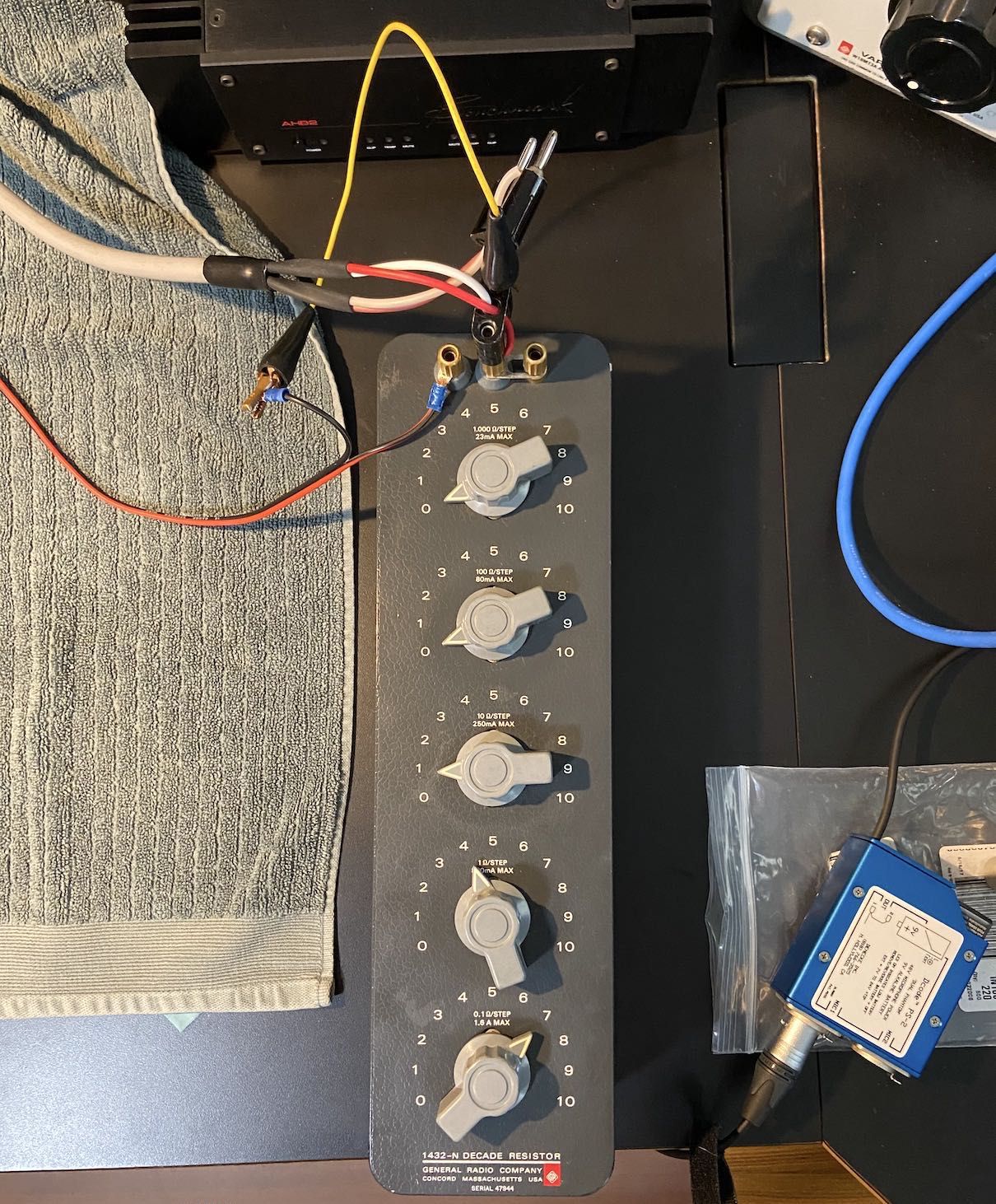
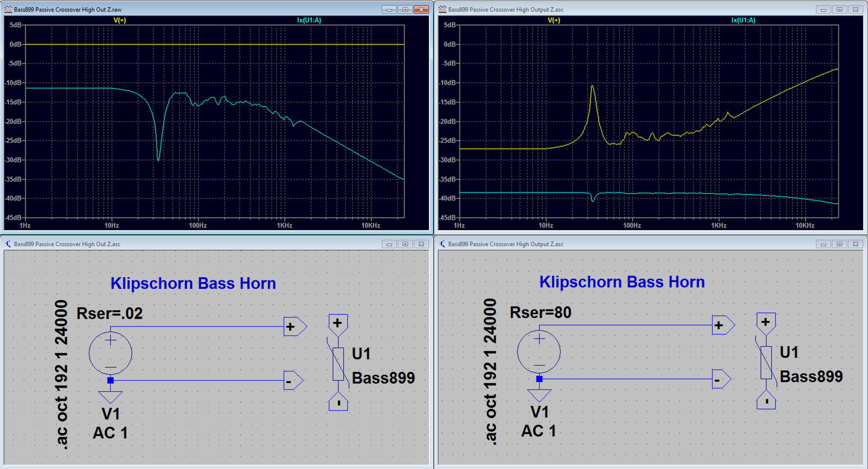
Just for fun... Here's a simulation of my Klipschorn bass cabinet, properly loaded by a room corner, no crossover, driven by an amp with a 0.02Ω output impedance vs. a First Watt amp with an 80Ω output impedance. Yellow trace is the voltage across the driver terminals and the Teal trace is the current passing through the driver. If you were to divide voltage by current, you'd get impedance c/o Ohm's Law. Since the two illustrations are very close to constant voltage (left) and constant current (right), you can see the driver/cabinet/corner impedance quite well in the other trace. I love this stuff. : ) It's obvious that a current source amp for audio application has a lot more to it than just a high output impedance. I need to read the links provided - thanks for the fascinating thread! : ) God bless you and your precious family - Langston
-
I just looked through some of @djk 's posts. He truly was a master. : ) This forum is gaining a lot of respect from me. I'm impressed with the respect I see between different posters, particularly the knowledgeable toward the newbies. Blessings - Langston
-
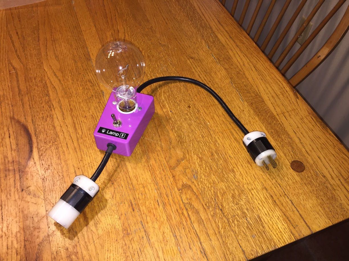
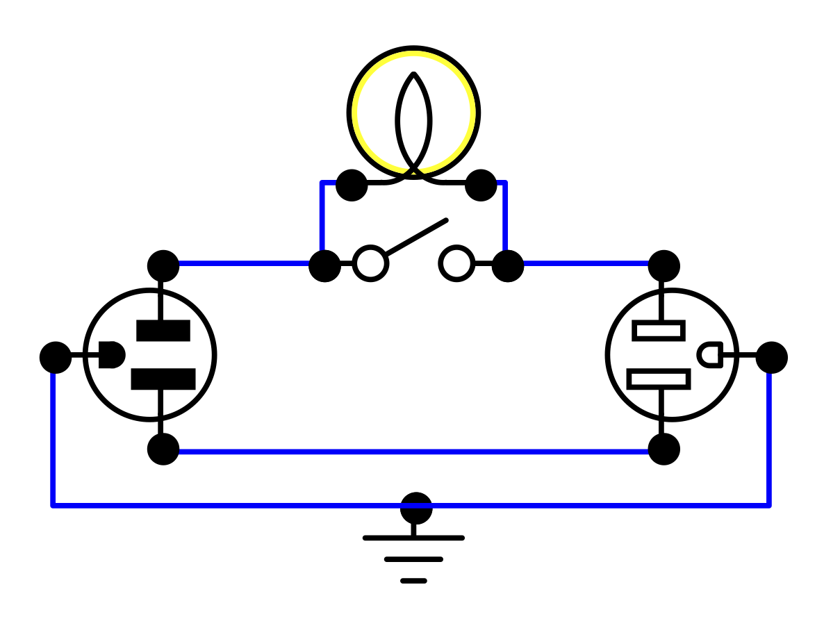
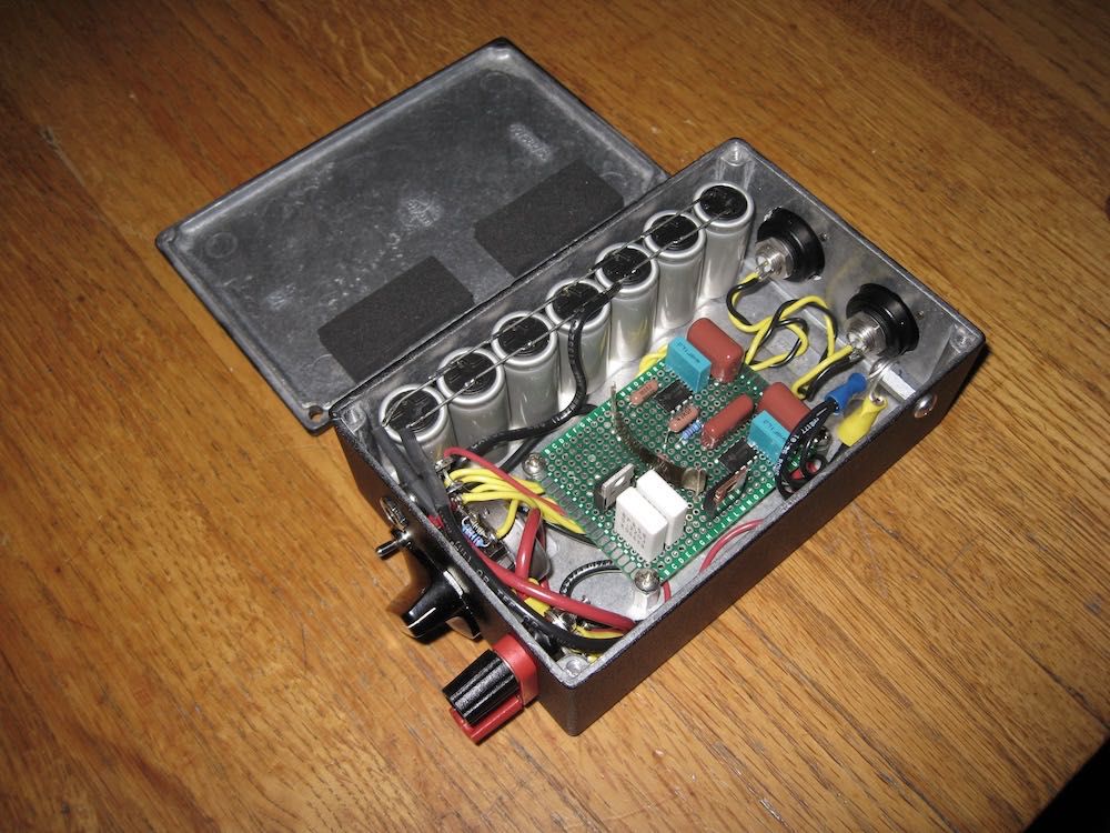
It's my understanding that limiting turn-on current is primarily a tube amp repair/restoration tool. The issue there is old capacitors that turn into resistors and fry tubes if switched directly to 120V after decades of of sitting in a closet. In that case techs generally use a variac and slowly ramp up voltage - but even that can result in damage to a tube amp - thus the light bulb limiter. I ran a concert production company, that means we supplied "backline", a term for rented musical equipment. This allowed musicians to travel lighter and specify certain tubed guitar amps, etc. be supplied by the promoter. Thus I became versed in tube equipment. Thus I built what you're asking about (though I still don't know if it reasonably applies to non-tube stuff). The deal with the light bulb in series with the tube amp is that if it got bright, capacitors had failed and needed attention, but given that the bulb when bright increases wildly in resistance, not enough current passed to damage the tubes and other stuff that wasn't broken. If the bulb was dim, the caps were probably fine. You add a switch to short the bulb once the amp started OK so that the full 120V is then supplied. A simple version. I found that a 200W bulb was required to pass enough voltage to the DUT: Rocket Science Schematic: Note: be sure the ground passes from male to female Edisons (that's the correct term for the 120V 3-wire plugs we use in America). : ) God bless you and your precious family - Langston
-
I learned about that stuff from the best audio transformer company in the world (they were bought-out, things may have changed); Jensen Transformer. I noticed Amazon offered sheets of it. Expensive. And I was able to use orientation and location to get the crosstalk way under what I felt was needed without that stuff. I was also concerned that the super high permeability metal would modify air-core inductor behavior (they are the problem) - not just inductance, but effectively convert the air-core into a cored inductor. So no dice. All turned out very well without that kind of thing. : )
-
I used two methods to determine cored inductor current saturation levels; the classic scope method using a variable pulse rate and width generator I made and by observing knees in the distortion traces with sweeps and a big amp. I noticed that the sweep method is more appropriate because the knee occurs before you can see it on the scope. My tough IMD acceptance threshold of 0.5% occurs much lower (maybe a tenth) of the current saturation spec. (mfg's use the scope/pulse method). I'm not saying it's a law of nature that you can divide the inductor current saturation level spec by 10 to figure out IMD or anything else. The good news is that my measurements showed huge variations between differing cored inductor designs with some of the least expensive coming out on top. IMO, given that extremely good performing inductors are inexpensive, it seems silly not to optimize this element of our addiction. My inductor torturing pulse generator (the inductors get hot) and schematic with notes: (link to designer's page)
-
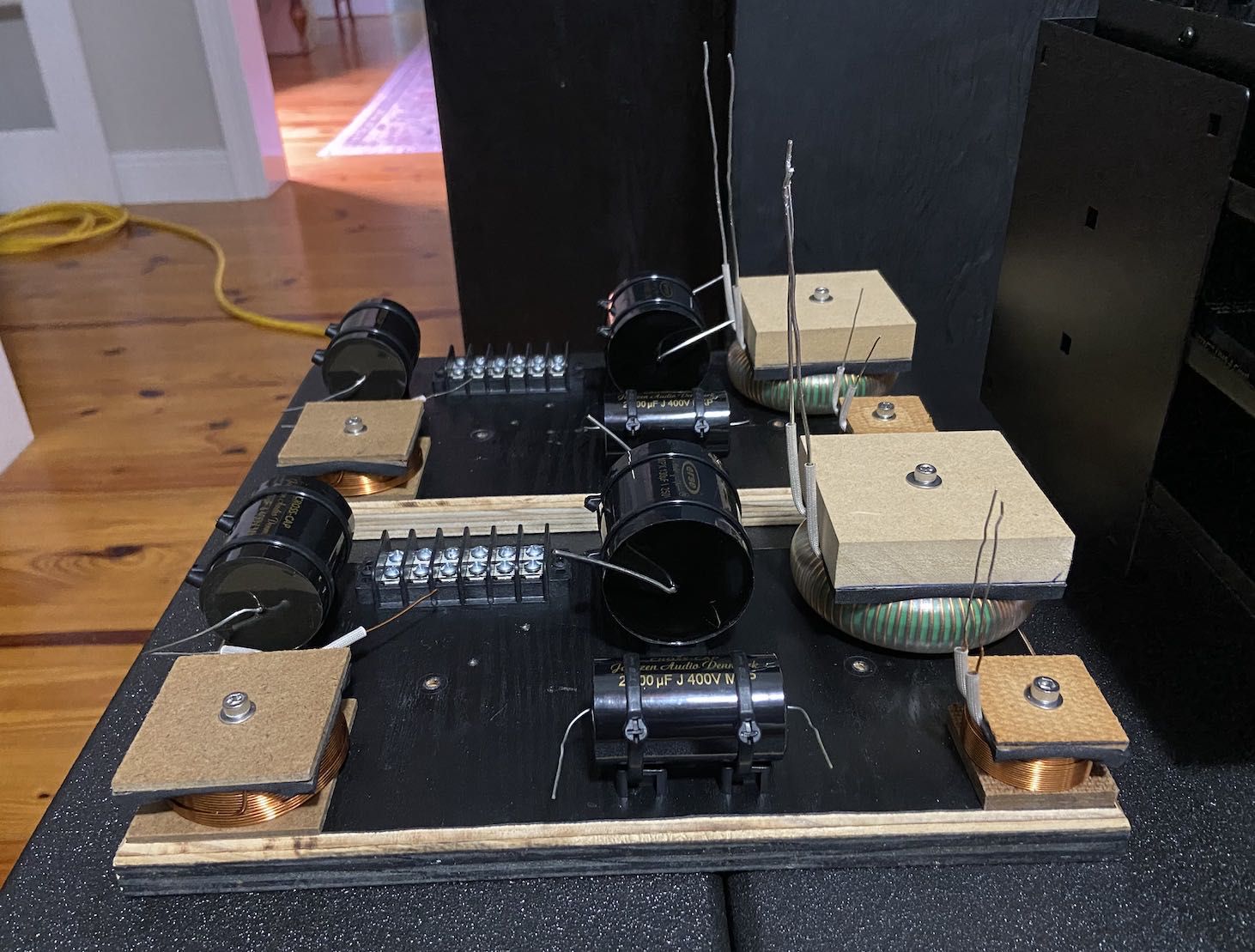
We're both odd! : ) I tried that using steel and copper plates and got small improvements out of it, like an additional 3dB or so crosstalk reduction, but it would have been a hassle to implement, so it failed the hassle/benefit ratio. Moving an inductor an inch or two, or changing its angle relative to the other inductors will change things by 10dB at least, sometimes much more. I've been able to easily exceed my goals in crosstalk reduction in this project by inductor location, angle and height (to align their centers). Here's early peek at the final design where you can see different thickness boards under the two air-cores to get maximum cancellation with the large iron-core toroid. The air-cores are aligned in the worst possible manner with each other so they would ignore the beast, so I used distance to reduce the crosstalk between them. I'll do a separate thread when the time comes for this Klipschorn mod, but the passive crossover's worst crosstalk is -72dB, and that's the larger air-core talking to the smaller air-core. Also, the smaller air-core is part of a CLR impedance compensation network parallel with the driver, thus less critical. Every other crosstalk combination results in less than -100dB. : ) God bless you and your precious family - Langston Edit: I just noticed that I should have swapped locations of the "beast" with the smaller air-core. That may have dropped the -72dB figure another 6dB or so. I'm definitely not gonna fix it. Fails the hassle/benefit ratio.
-
I'm leaning in that direction given certain assumptions that resulted from what I learned from the measurements. Which measurements would most likely expose the devices' audible defects in use and how to simulate that setup took me about a month to figure out. It is for my '74 Klipschorn project. In the past I wouldn't have even considered passive crossovers, but now that I'm so comfortable with inverse filtering (removing selected resonance and transfer function aberrations through FIR convolution), that I think I can achieve audibly indistinguishable results using passive crossovers and a single amplifier channel. It's a heck of a lot harder, and that's a huge plus. : ) Assumptions 1. Cored inductors are selected that don't change characteristics due to vibration. 2. Cored inductors are selected that remain low in IMD up to the peak current that will pass through them in a given circuit. 3. That inductors of any type are located so that none receive more than -50dB crosstalk from any other inductor. This is fairly easy stuff to achieve and the fact that most pictures I see of passive crossovers violate at least #3 tells me that you're right - many people listen with their eyes and manufacturers listen to their accountants. I think beauty follows function. Anybody that's been married a long time will tell you that. : ) God bless you and your precious family - Langston
-
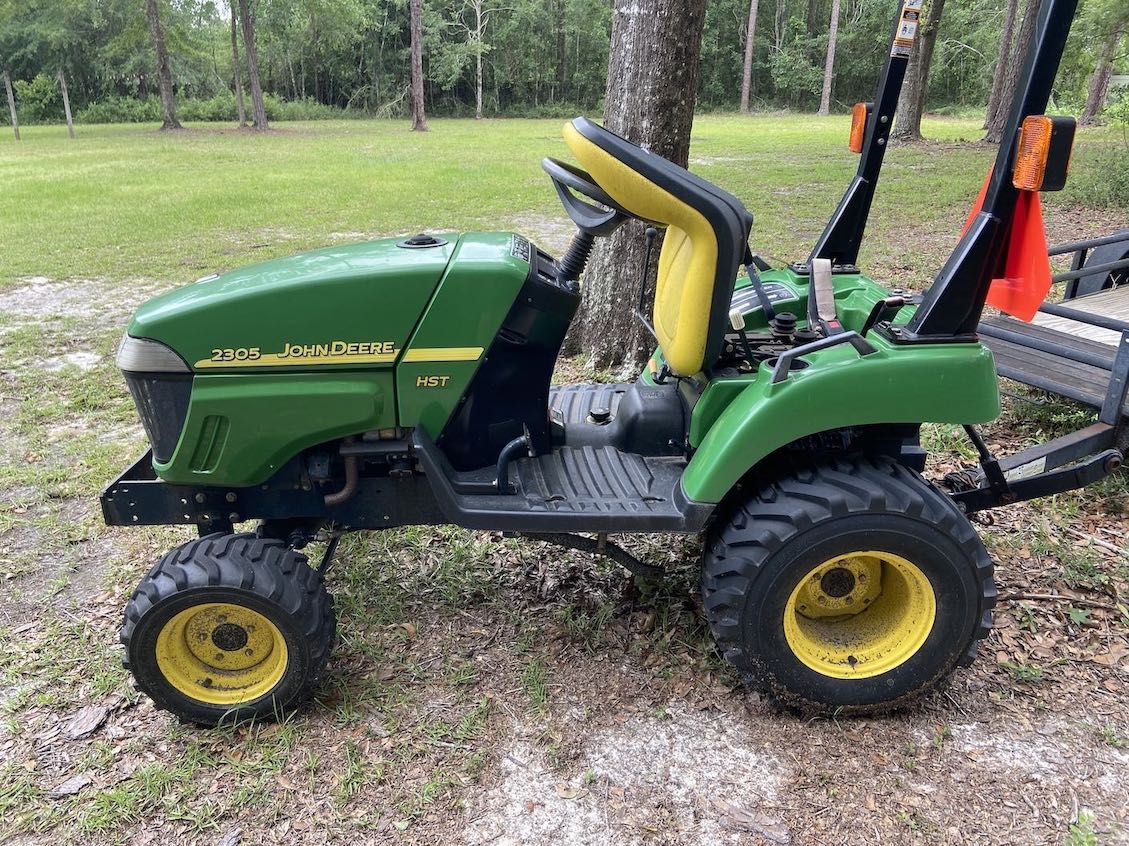
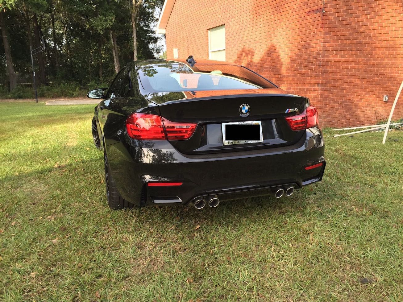
@mustang_flht, Unbelievable! I also have an American and German sports car. First up is the American all wheel drive that can do 0 to 60 in.. Well.. Actually it can't even do 20, but it is reliable. Forgot the year - got it a long time ago: And my German sports car. 2016. It will go 60. : )
-
BTW, when measuring amps always measure directly from the amp terminals, not at he end of the cables that connect to the load. If you do the latter, you'll form a voltage divider (attenuator) made up of the amp's output impedance and the impedance of the cables. Not good when your goal is to characterize the amp. God bless you and your precious family - Langston
-
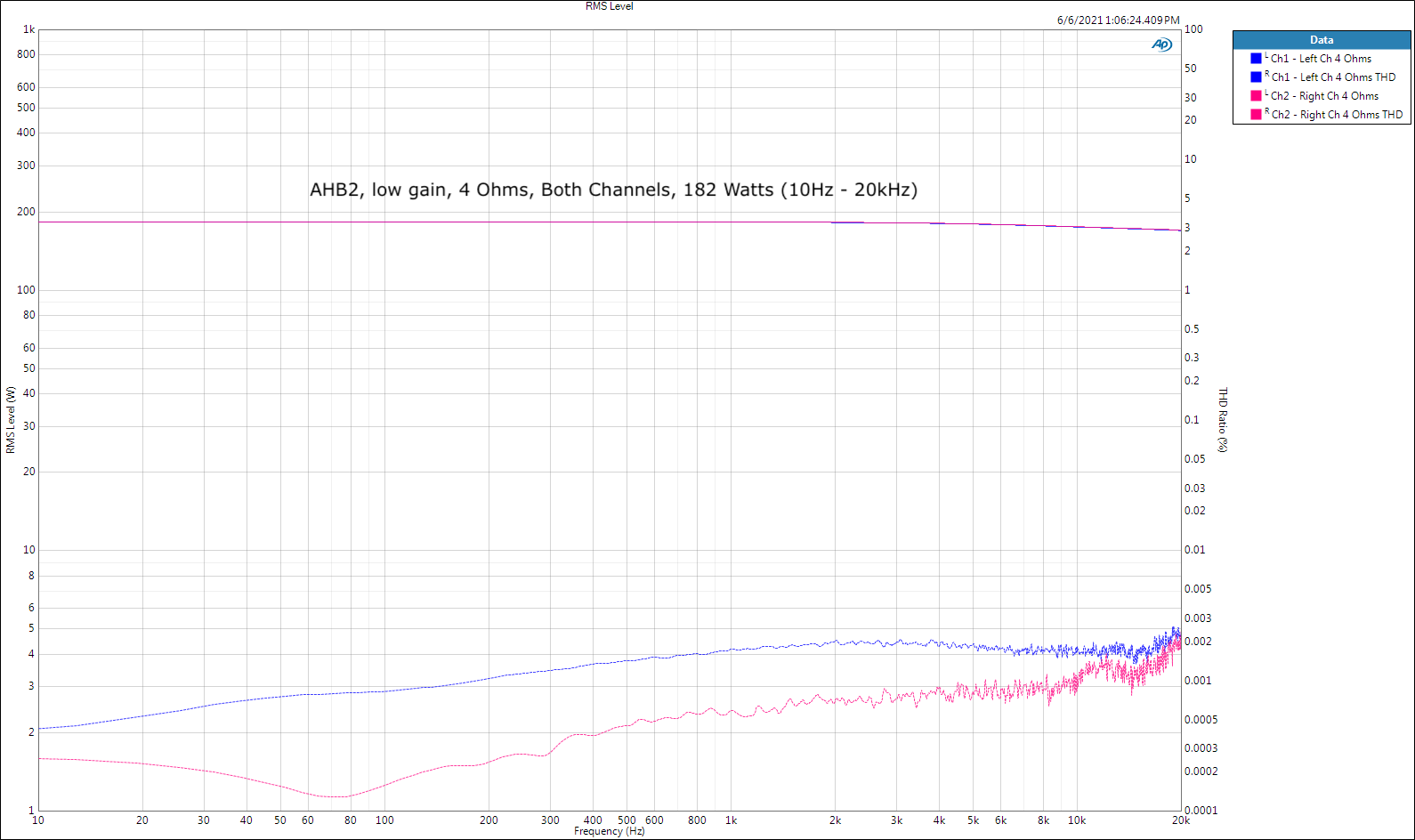
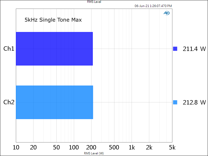
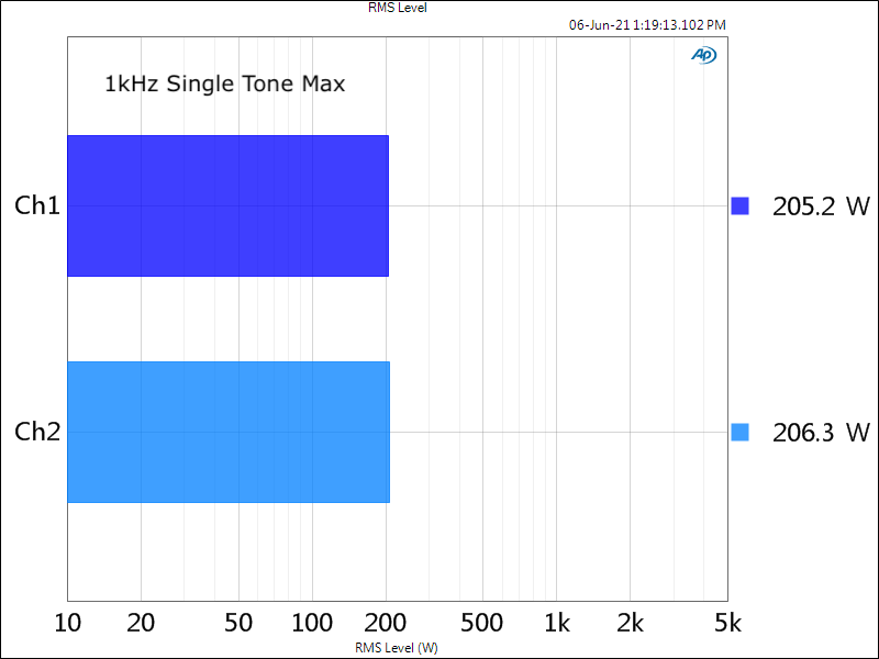
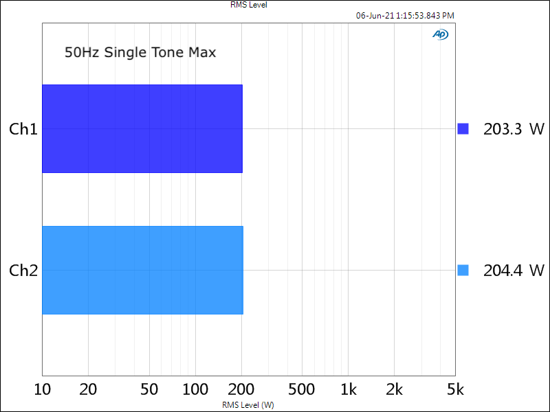
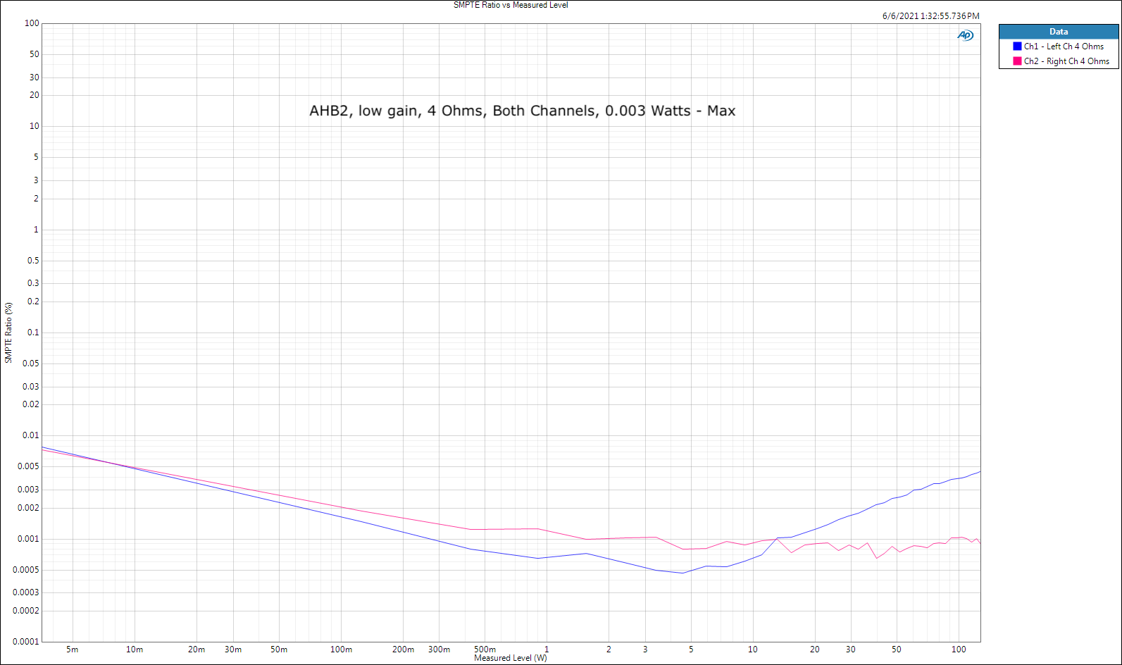
@Deang Asked about measurements of this amp beyond the standard 1kHz. I was kind of surprised myself when I noticed that wasn't easy to come by, thus a few measurements of my unit that's a few years old and working perfectly. This is also for the crazy Frenchman that goes by @mustang_flht, has a picture of a Mustang for his avatar YET has a German sports car! : ) I only have two 4Ω power resistors (4Ω is my life), so I couldn't do two channel 8Ω measurements. 10Hz - 20kHz THD SMPTE IMD Single Tone Max Outputs at 1% THD (into 4Ω) God bless you and your precious family - Langston