captainbeefheart
-
Posts
1422 -
Joined
-
Last visited
Content Type
Forums
Events
Gallery
Everything posted by captainbeefheart
-
The magnet wire on the coil is extremely thin. It also has a thin layer of insulation covering the outside which makes it hard to get a resistance reading with a meter by just touching it. If you can read through the voice coil, which sounds like you can then re-connect the thin magnet wire to the terminal. The heat from soldering should melt the insulation off the magnet wire in the connection or you can clean it off before soldering.
-
I'm glad Henry was helping with measurements because I was going to just blame the OPT for the treble roll off. Since Henry was getting the same roll off with the Hammond's I figured something else had to be going on which looking closer at the 6Y6 in triode mode's input capacitance and the source impedance of the driver stage the numbers fit perfectly. I even checked with a simulation since I dismantled the breadboard sweetie circuit. Miller capacitance is rearing it's ugly head. There is enough gain to which one could try and change the 100k plate load resistor for the 6SJ7 to a lower value, maybe try 82k which should help lower the output impedance of that gain stage. This should bump the corner frequency past 20kHz and only bump the open loop gain from 17db to 15.5db. Since the limitation is in the circuit itself and not the output transformer than I change my advise to not spend big money on a high bandwidth output transformers.
-
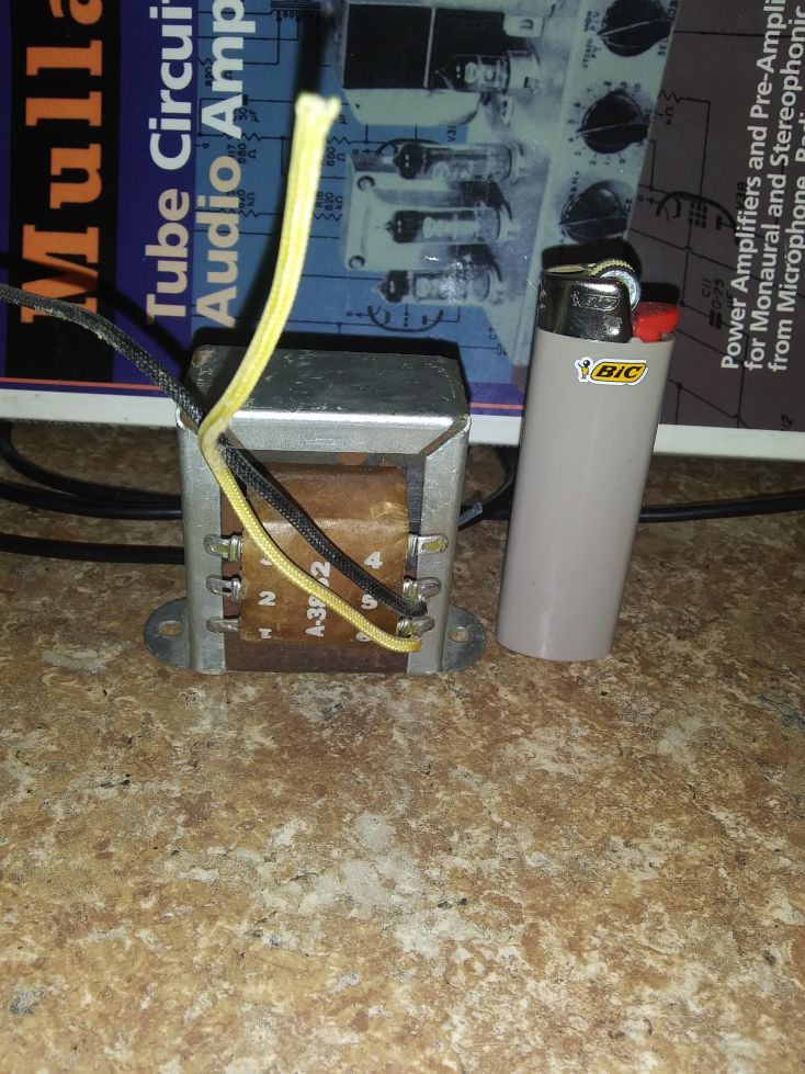
This is the Universal Stancor OPT I used. I think I paid like $15 each for several of them. I like to use them for push pull guitar amps. Ya I know, it screams hifi 🤣 It's actually 18 watt push pull but Stancor says you can use it for a single tube in the datasheet which I don't recommend. They must have added a very small air gap for this purpose. I just set it up for 10k plate to plate load impedance and connected a 10M45s to the other plate tap and adjusted current to null DC component in the winding. Works just fine since it's Class A. The bass sounded decent actually. I tried it with the single plate connection and center tap as Stancor suggests but the bass was not so good. It works but the minimal effort to hook a current source up to the other side was only fair to assess the Sweetie as best as I could.

-
Even my really cheapo OPT sounded fine in the bass region. Our speakers don't go very low and most of us use sub woofers anyway. Often OPT that do very well in the bass region will be a trade off from the high copper giving poor high frequency extension. The higher the impedance of the load needs the worse this problems gets, hence why I like to choose tubes that have a low plate impedance where I can use a low load impedance. A 3k:8 transformer will be much easier to get both good bass and treble response say compared to a 10k:8 transformer. It's still possible but the transformer manufacturer will need a more complex winding/layering design. This is how they get very expensive quickly if we want excellent bandwidth in both directions.
-
I just double checked and the high frequency roll off isn't from the output transformer so I do apologize for that assumption on my behalf. The high frequency roll off is definitely from the circuit itself, from the high output impedance of the 6SJ7 stage and the input capacitance of the 6Y6. Of course layout will give some differences in stray capacitance, my breadboard had more than Henry's layout but it's no coincidence that we are getting very similar roll offs with completely different output transformers. The sonic impact this has on fidelity is completely dependent upon how good your hearing is like Henry said. Most of the old timers may not even notice it while the younger guys with excellent ears will. I even noticed it right away but just thought it was my really crummy OPT was the cause. I should have known better. I have made no feedback SET amps with two stages before and ran into the same problem with high impedance driver circuits. I eventually just stopped doing two stage circuits because with low powered SET amps I feel that Class A2 has a large advantage so I always have a buffer between the voltage amp stage and output triode. With Class A1, two stage designs I was using high gm pentodes like the 6EJ7 wired as a triode. It gave excellent gain, very low output impedance to drive the output triode input capacitance, and plenty of current to not run into Slew rate problems. With a 300b tube one may require 140v peak to peak to reach full power and so since slew rate is a large signal phenomenon the output triode grid capacitance needs to be charged up fast enough. Wimpy high mu triodes and sharp cutoff pentodes didn't have enough current to reach 140v peak to peak into 300pF at 20kHz. With the Sweetie and it being 1 watt there isn't that much swing and 1ma of current should suffice just fine for enough to drive 60v peak to peak into the 6Y6 grid capacitance.
-
I wouldn't say it's just to "chase numbers", harmonics from instruments such as cymbals, piccolo, and violin all extend up to 20kHz. The overblow/breath/air from female and even male vocals extend up that high. High fidelity is to recreate ALL the detail in the recording that anyone can hear. I have excellent hearing for an old guy and I noticed it immediately. Which is why I added the feedback to increase the bandwidth. The designer himself said that people are sensitive to phase shift and with -3db at 18kHz there will be significant phase shift in the audible spectrum. Did you happen to measure the low frequency bandwidth? With the 300b in George's amp it was -3db at 11.7Hz and it's starting to roll off at 30Hz. The 300b has lower plate impedance so I figure the 6Y6 won't have the same roll off characteristic. My guess is it will be around -3db at 20Hz and start it's roll off much higher. Even with my cheapo OPT the bass on my full range mono setup wasn't bad, I only noticed how dull the recordings sounded which led me to look into the high frequency domain which showed I was losing the high frequency detail from the recording.
-
Thank you Henry for actual measurements. Strange.....that is eerily similar to what I was getting. I was -3db down around 18kHz and assumed it was my OPT. I started thinking what else would cause a roll off and it could very well be the 6Y6 input capacitance and the high output impedance of the 6SJ7 Pentode which the load resistance 100k dominates. Rough calculations of the RC low pass filter caused by driver tube and 6Y6 input capacitance and the -3db point is right around where we are measuring. Interesting, the high frequency roll off most likely isn't the output transformer but the actual circuit. Power triodes have very high input capacitance compared to pentodes and they require low impedance drivers in order not to get a roll off in the treble frequencies.
-
Hammond is decent, they are $63 each so that's $126 for a stereo unit. That's not including shipping. I was using a cheapo transformer which costs about $20 each, and I do not recommend. George was measuring with a 300b tube at 70mA in a completely different circuit. The 300b has about half the rp as a 6Y6 if I remember correctly. Do we have any Sweetie measurements with Hammond or Edcor?
-
Advice to anyone building the Sweetie or any other zero feedback SET amplifier is if you want excellent performance and sound then I would think long and hard about the output transformers and make certain you use a very high quality one. Another member mentioned Lundahl and I second that, their amorphous C core output transformers are excellent. If it's just a fun project and ultimate sound quality isn't necessary then use whatever transformers you want. It was really no surprise to me that the output transformer I used didn't give the best bandwidth. If you find your build is lacking in treble frequencies and you are not an ideologue against negative feedback then add the 2.2k resistor and see if there is an improvement. It won't ruin the SET sound contrary to belief. It's such a small amount of feedback, and around only two stages there shouldn't be need for compensation. Trust your ear and use whichever you like best. https://www.lundahltransformers.com/wp-content/uploads/datasheets/1663.pdf
-
I was only sharing my experience on building the Sweetie, well half a sweetie. As I mentioned I used an inexpensive "universal" SE output transformer with the circuit and since my bandwidth wasn't great I decided since the circuit had enough gain to just add some feedback. It's such a small amount of feedback that it shouldn't cause any trouble around just two stages. I found that a little feedback improved things for my situation. By no means is adding -7db of feedback going to drastically change the amplifier into something else. I did get lower distortion of course but there is still plenty of second harmonic distortion, it certainly didn't disappear. I was more concerned with bandwidth and output impedance which is why I added the feedback. I am in no way trying to change the original design at all, nor am I saying it's a bad design. Someone else may also not use the best output transformers like me and find the feedback helps their situation. With cheapo output transformers take care not to use too much feedback unless you know what you are doing, the -7db with the 2.2k resistor is a safe amount and shouldn't cause troubles.
-
Of course there are stability criterion for feedback. You can't just go adding it all willy-nilly. Take three cascading stages all AC coupled. If each of the coupling capacitors produces a phase difference of 60° at the same frequency, the total phase shift adds up to 180°. This amounts to phase reversal. If the feedback starts out as being negative for this particular frequency it will convert into positive feedback. The critical point is a loop gain AB = 1 With the Sweetie being only a two stage amplifier and combined with the negligible amount of feedback I added there were no real reasons to bring up stability. I really don't see a need to bring this conversation to another forum. I'm sure there are plenty of guys in here interested in the topic and our conversation could be educational for them.
-
Since the Sweetie designer is asking me about his circuit with feedback I feel I still owe an answer to his original question. I already gave some distortion figures of the Sweetie with and without the feedback. As for why I added the feedback originally wasn't only for the distortion aspect, it was also because I was getting a roll off well before 20kHz. I assumed it was the cheapo universal output transformer I was using wired for 5k:8 operation. Without any feedback phase shift at 20kHz was already -80° and with the 2.2k feedback resistor added it reduced phase shift at 20kHz down to -40°. -40° phase shift at 20kHz isn't great but it's a lot better than -80°. Compared against another amplifier I made with some decent output transformers and -20db of feedback I was getting only -20° phase shift at 20kHz. This was a 3 stage amplifier also which of course is going to have greater phase shift from the extra stage. I think there are two current builds I have seen of the Sweetie, one with Hammond OPT and the other with Edcor. I would be very curious to see what the phase shift in your builds are. A] Because of the better OPT; and B] Probably better layout compared to my breadboard. I had flying leads and so my stray capacitance was most likely worse than a tidily built amplifier layout.
-
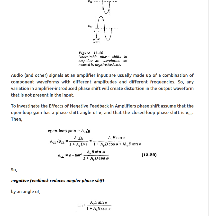
Negative feedback reduces phase shift
-
I fail to understand the question. In amplifiers the feedback fraction B is constant; it does not change in either magnitude or phase as we change frequency. The internal amplifier gain A is the part that changes with frequency and produces the phase shift. All amplifiers possess reactance, the coupling capacitors produce phase shift at low frequencies while stray capacitance in plate circuits cause them in high frequencies. Phase shift is already present in your Sweetie Amplifier along with every other open loop amplifier. If phase shift is an audible problem then that would actually be an argument FOR the use of negative feedback since it reduces phase shift in the amplifier. In order to not have phase shift in the audible frequency range one would require the amplifier to have very wide bandwidth; negative feedback increases bandwidth and so reduces phase shift in the amplifier.
-
If you really want to hear the 6Y6 in triode mode as clear as possible with no feedback I highly suggest swapping out the 6SJ7 for a cleaner driver circuit. Don't get me wrong I use the 6SJ7 and like it a lot but in the Sweetie it's gain is a tad over 50 which is fairly low for this tube. Triode strap something like a 6EJ7 with a 15mA CCS on the plate and Rk = 220. You'll get more gain and at 60v peak to peak output it's only around .2% THD. Now that's a very clean driver for a no feedback amplifier.
-
How do you know you are really hearing the 6Y6 in a no feedback circuit? The 6SJ7 is supplying the input signal to the 6Y6; I ask is the signal taken from the 6SJ7 plate a perfect copy of the input signal? It's not, with the Sweetie producing 1 watt output the 6SJ7 already is producing 1% THD from it's output alone. So you are never hearing the 6Y6, you hear the whole circuit which in these amps the driver can produce as much distortion as the power tube. Since the global feedback doesn't just clean up the power tube distortion but also the driver, you may actually be hearing the 6Y6 more with feedback since the 6SJ7 will produce a much cleaner output to drive it. E.g. The signal isn't already tainted with 1% THD before even reaching the 6Y6. So how can you give the 6Y6 even a fair listen when it's input signal is already heavily distorted? Driver stages in two stage SET amps are extremely important, almost more so than the output tube. I spent a lot of time on driver stages for SET amps and high gm pentodes strapped as triodes work very well when CCS loaded. I am one of the few people I suppose in the market for a SET amplifier that can do all music genres well. The great part about triodes is they require very little feedback to get fantastic results. Try and remember feedback is not bad, it's why triodes behave the way they do. It's when designers don't properly apply feedback or just use it as the only means of linearity. It's not magic, it can't make everything good, but when you have a great start with triodes just a tad will make a good amp a great amp.
-
I'm very curious what type of music you listen to? I'm not in the camp of thinking that distortion must be as low as possible, but I do believe there is a point of too much even if it's only second harmonic. With simple styles of music very high second harmonic distortion isn't as much of a problem, it's when you get complex signals and demanding program material where too much distortion just doesn't work due to the amount of intermodulation distortion. Basically the harmonics don't play nice with each other with certain types of music. There are merits well beyond the distortion aspect of negative feedback, the control of the speaker with the lower output impedance is a big advantage along with reduced noise floor are all welcome in my book. I don't think one needs to play with the amount of negative feedback with the Sweetie because there just isn't enough gain to do so. Using more than -7db and you will require more than your average source can deliver to reach full output power and anything less than -6db of negative feedback isn't really going to be much worth it as it will just pretty much sound the same as with no feedback. That's the best part about Triodes, they don't require gobs of negative feedback to reach excellent numbers, but I do think they need some in most cases. If someone has say K-horns or La Scalas and they listen to quite simple music at moderately low levels than a simple triode amp with no feedback can get you by or even sound great with all that coloration. But once you start getting a full orchestra or some slamming Electronic Dance music especially with direct radiating speakers like a Forte, Heresy, or Cornwall then the amp needs control (low output impedance) and low enough distortion to sound good. Although my La Scalas and K-horns seem to do better with these high output impedance amplifiers they still perform better with a more controlling amplifier. There are two aspects where these types of amps produce a mirage of "good bass". One is the resonant frequency down low that gets agitated and so the listener is tricked into thinking this "one note bass" is superior. Then there is the fact that the output transformer starts to saturate at low frequencies giving rise to even more excessive distortion. Since this type of distortion is very non-linear it gives rise to even harmonics. The second harmonic of say 35Hz is 70Hz, this new signal of 70Hz that wasn't there before reinforces the 35Hz fundamental frequency. I have seen over 30% THD at 35Hz with some of these amps and it's amazing that it still doesn't sound terrible. 30% THD is not hifi no matter how well masked it is and although it will sound novel and exciting at first, for me it gets old quickly. I have seen people swap out these type of amps for SS amps and say the SET amp had "better" bass. But once their ears gets used to accurate reproduction with tight bass it becomes apparent the average SET amp in many cases is a 1 trick pony that only does simple music well. Just my opinion so please don't take any offense. I find that people that prefer these "no feedback" amps listen to very simple music at lower volumes.
-
At what cost? The cost is -7db in gain. Which isn't enough to cause stability trouble if that's what you are worried about. I find this fascinating. What's the difference? Why can't one use feedback with a SET amplifier?
-
The amp has plenty of gain for just 1 watt of power; ~17db I added a 2.2k resistor from the Sweetie's speaker output to the 6SJ7 cathode which gave about -7db of feedback. It cleaned it up a lot but not sterile clean by any means. I didn't write it down but remember around 1 watt at 1% THD. So with one resistor you can get less distortion at 1 watt than you are getting at 1/4 watt output now. An input of 1v will bring you to 1 watt output. *Note: I was using 560 ohm cathode resistor for the 6SJ7 and it wasn't bypassed with a capacitor.
-
Thank you for double checking your measurements. That looks pretty much spot on to what I was measuring - 1.42% THD at 1/4watt. With the larger fundamental frequency now the 60Hz noise looks much better.
-
That's quite a lot of 60Hz being modulated into the 1kHz fundamental. 60Hz is literally only -10db below the second harmonic. I'd say before looking into chokes figure out where all that 60Hz is coming from. Once you clean that up then we can see how much of the power supply ripple is actually getting through. As for distortion with the Sweetie, I'll have to double check through my folders because I thought THD was much higher at 1/4watt output. I only mocked up one channel to my variable DC bench supply. I just want to make sure you are measuring the correct output amplitude into 8 ohms for 1/4 watt 1/4 watt = 2v peak output into 8 ohms correct? I just wanted to make sure we are on the same page in regard to peak voltage across the load while looking at ARTA. 1/2 watt = 2.8v peak 1 watt = 4v peak
-
Maintain / upgrade my old Heresys?
captainbeefheart replied to TheGoodTexan's topic in Technical/Restorations
You don't have to see any actual measured data, knowing the crossover design impedance characteristics and capacitor dielectric properties; specifically dissipation factor you would know that ESR could change high frequency response. I just looked at a polyester and foil capacitor datasheet, DF = .7 Now compare that to just about every Polypropylene capacitor that has a DF of .1 or better. Since DF is a ratio between ESR and Xc the math tells us that ESR will be higher for a capacitor that has a DF of .7 compared to .1 or less. 2uF at 10kHz Xc = 7.95 Between the two capacitor types, one with a DF=.7 and the DF=.1 Polyester and foil ESR= .7 * 7.95 or 5 ohms Polypropylene ESR= .1 * 7.95 or .79 ohms So with one cap we have an ESR of 5 ohms at 10kHz while the other only has an ESR of .79 ohms. At higher frequencies the transfer function has changed due to the difference in ESR which is directly related to dielectric DF. The polypropylene capacitor will be brighter sounding since it has less losses at higher frequencies due to lower ESR. The lesson is, if you don't have a thorough understanding of the networks and overall good working knowledge of passive filter design then replace the capacitors in your networks with the Klipsch approved JEM capacitors to make sure you retain the intended transfer function of the filters. @Deang -
FS: Fisher 400C tube preamplifier
captainbeefheart replied to captainbeefheart's topic in Garage Sale
Sold -
I'm getting around 2.5% THD at 1 watt power 250mW of power 1% THD
-
That PCmag article is a pipe dream. It's a theoretical number in a perfect situation with all panels producing it's 100% full rated output and zero losses. Elon is a smart guy no doubt but that article is just a poster child trying to sell something that will never work. It sounds nice, and can certainly help with energy production but at best it may become enough to cover half the demand we require. In 2021 we averaged 3.9 trillion kWh per day. Once you crunch the actual real numbers you end up at least doubling the area "technically required" and the system becomes massive. Then we are going to replace 200 square miles of panels and another 200 square miles of batteries every 5 years or so? The longer they are in service they produce less power, this increases the original square miles even more to account for those losses over time. That or replace them which is insane. It's never going to work and there must be a better way. At best it will be an addition to the system, maybe at best cover 50% our demand needs which is great. But to say we will one day run completely off solar is never going to happen.