captainbeefheart
-
Posts
1422 -
Joined
-
Last visited
Content Type
Forums
Events
Gallery
Everything posted by captainbeefheart
-
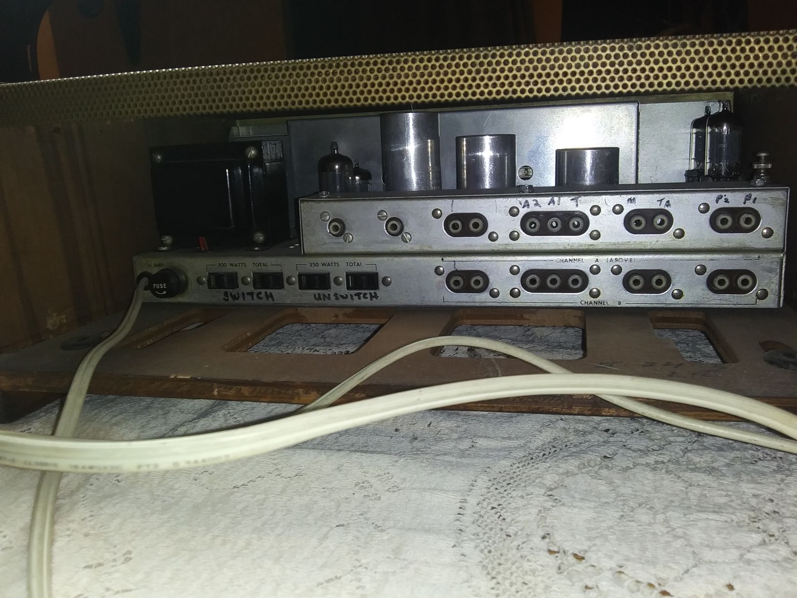
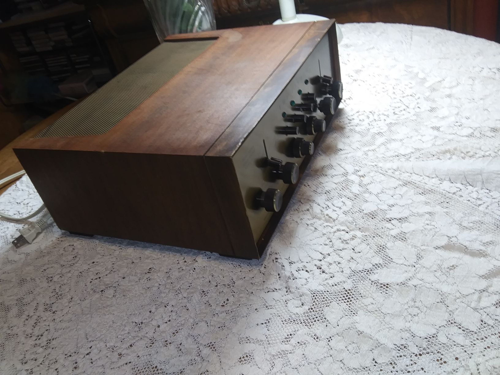
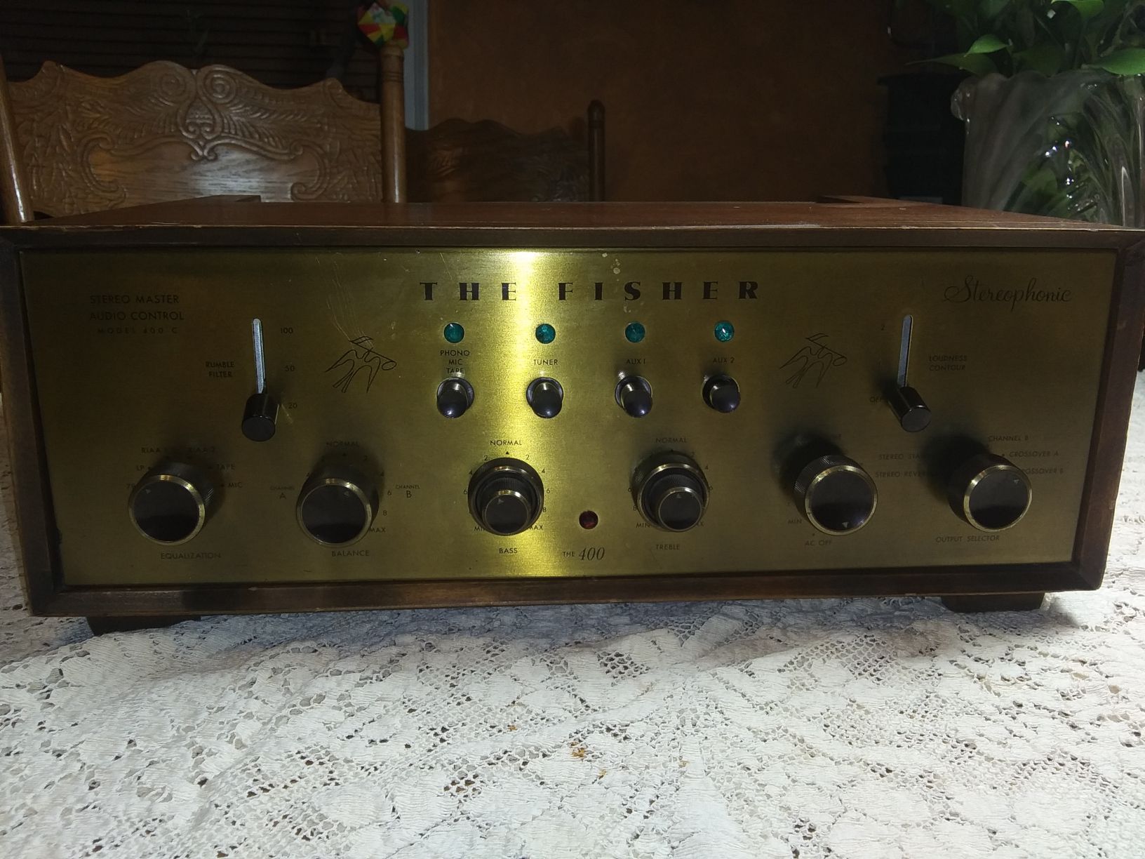
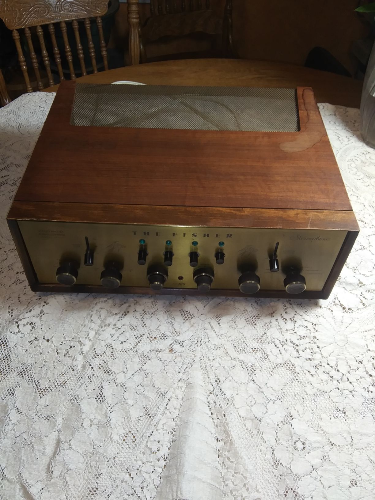
FS: Fisher 400C tube preamplifier
captainbeefheart replied to captainbeefheart's topic in Garage Sale
pics
-
$1,200 shipped obo Loaded with all Telefunkens and sounds glorious especially with vinyl.
-
I agree, EV is off topic. If OP wants to post his cost per kWh, monthly usage, and rough area in ft2 he has for panels we can work out a mock up for his returns.
-
You could cover every inch of land in the USA with solar panels and it wouldn't come close to meeting our demands for energy. For EV's - rare earth metals are just that, rare. You mentioned sustainability but how can something extremely rare and costly to mine be sustainable? Is that scientific enough for you? You brought up sustainability which encompasses many facets from cost to disposal. Very little of what I said was political, I only mentioned helping our allies as a benefit of our great resources. If you want technical arguments I can provide many detailed analysis of why solar/wind cannot handle our demands. I'm an EE and so have always been fascinated and love electrical power. I'm far from against it, I'm only being realistic about it.
-
You call mining rare earth metals and their toxic disposal sustainable? Learn what it's like to mine Lithium and come back to us. Our own leader helped China get the largest Cobalt mine in the hands of Chinese. You call being stuck having to purchase batteries from China "sustainable"? I'm sure you have heard of supply and demand before? What happens when everyone in the USA is required to own an EV? The price of these rare earth metals will become even more expensive since the demand will only increase. Price will not go down, it will only go UP. We produce and refine the world cleanest fossil fuels. We have vasts amounts of these natural resources right here in our land. We should be pumping and refining as much as possible while we are still using crude for means of energy. We should be exporting as much as we can to Europe so they don't need Russia or Opec+. This has multiple benefits for us and them. It will greatly help stop funding Russia's wars. We won't take advantage of our own resources while we go and beg hostile foreign adversaries for their oil which makes us the biggest laughing stock on Earth. We are going around begging for something that we already have right below are feet. It makes ZERO sense. Especially since our sweet crude is far better than their sour sulfur filled crude, our oil and refining is actually the greener and more environmentally responsible oil. We can never fully go to EV's, it's impossible. Solar/wind will never replace our regular means of power generation, it can't. Until we have other avenues we are stuck with oil/coal which is fine as long as it's done responsibly.
-
Each channel's pair of EL34's has their own 6.3v winding. I had him measure filament voltage, he has correct voltage on the channel that works and the dead channel has nothing from it's winding. From pictures the wiring goes down under the PCB and into the power transformer, no visible fuses for the filaments and most likely needs a new power transformer. We stopped further testing because the unit is under warranty and so he is going to send it back to get it fixed with just cost of shipping hopefully. I am trying to talk the OP out of doing their "upgrade packages deals" which in my opinion are not actual performance upgrades but more snake oil based. First stage is they replace coupling caps, tubes, diodes, resistors, with name brand boutique types. Second stage was in/out jack upgrades which isn't going to yield sound improvement but nice jacks that hold tight can be nice. The original stuff on the amp is just fine in my opinion. Third stage is getting to the real snake oil stuff, they add those bybee quantum purifiers which are just a low value inductive resistor in a molded body. How do I know? I'm not the only person to cut one open. I would never purchase one but a group of us pitched in enough to get one to test and cut open. What a disappointment but to be honest not a surprise from the world of "hifi upgrade" market. Fourth stage is they rewire the amp with some expensive wire. For those of you out there that change your internal wiring with your amplifiers do you also measure phase shift before and after? I doubt it. At the very least maybe some square wave tests would be nice to see if anything has changed enough to be audible. It's really not the wire making the sonic difference, it's the layout and slight differences in parasitic capacitance. The Black Ice F22 doesn't have much open loop gain even though they have two 12AX7's per channel, that's four high mu triodes yet they only use 4.5db of feedback. It's a two stage amplifier for those that don't know. Yes that's right, only two stages with 4 front end triodes. They call it "Odyssey circuit technology" or something like that. Nothing new here, just long tail pairs in the front end with a new name. It's funny they say the lower gain has lower distortion because of the lower negative feedback. It's actually the opposite, gain is easy to achieve even with two stages and higher amounts of feedback will give lower distortion and lower noise. At 50 watts it produces 1% THD. All this "new" technology they claim and my old Fisher 200a amps from the 1950's better it by a huge margin. They produce 60 watts from a pair of EL34's at .1%THD. That's 10x lower distortion with more power with "old" technology lol. And no bybees required All of these "upgrades" ring in at $800, which is crazy money and they don't even show any before and after measurements to show what was improved upon - only subjective terms are used of course from only listening tests.
-
The power tube heaters for the dead channel do not light up. I'm pretty certain the heater circuit would be the best place to start troubleshooting.
-
Can you open the amp up and take some pictures of the internals? I believe those share a power transformer but each channel has their own transformer winding. The two wires for each channel go from the power transformer to one socket, then they daisy chain from that connection to the other EL34 socket with two more twisted wires. The heaters do not have a fuse. Either the two wires going to the socket on that channel has a bad connection or the winding failed and you will need a new power transformer. If you post pictures I can annotate them in editing software to show you what connections and wires to look at and test.
-
For the average solar panel setup by the time you might break even it will be time to replace the panels, batteries and inverters so it's a wash. I know this for fact because one of my good friends is in the electrical generation business but also works on pump stations and solar generation systems etc.... He has told me for the average homeowner it's a scam and that makes sense crunching the number here in New England. Now if you can utilize enough area to generate enough power where you basically become a small power generation company then it would be worth it. But that's for someone with lots of land and even better in a location where you get lots of Sunny days year round. The average roof top setup in New England is a bust for the majority of people that paid out $20k for the setup. My friend gets called out because often the company that you paid to install the system won't help when you are still paying about the same for your electricity, maybe $50 less than what it was without the solar setup. Most people call the company after a few months asking if it's working properly because they aren't seeing the gains they were quoted. The company comes out and says all is well and there is nothing they can do about it. Then my friend gets called out to inspect or troubleshoot the system, after he sits down and explains it to them why they aren't yielding what they were told then the customer usually becomes very upset and looks to get him in the middle of a fight to which he obviously will not. I guess he leaves with the bill a professional assessment that they can use for their argument against the company but little recourse can be made once it's all installed and you have forked over the cash. If you can DIY it's a no brainer since the markup is crazy with these companies. Do your own research on panels and get the best ones, often these companies install the cheapest ones possible that won't last a decade, the good ones will output for about 10 years then need to be replaced. Batteries same deal. Most places will not even allow you to store your energy into batteries and require you to feed back into the grid what you aren't using and you only get a credit towards your bills. Setup costs for these systems are less expensive but also if you do not produce enough power it's a losing situation. With enough power it's worth it but that exception and not the general consensus by far. I'm not for or against solar panels, I'm only saying it's situational which the companies selling the systems won't really tell you as they promise the holy grail answer to energy production. I advise contacting an engineer that is not in the business of selling the systems to crunch numbers for your specific situation. It could be an electrical engineer or master electrician that knows about the systems and can work through the numbers for your specific situation. Me personally would never put anything on my roof for multiple reasons but the majority of people with them on the roof don't gain much from the systems anyway unless your energy consumption is already extremely low. Having your average monthly energy statements ready is needed to work out how much power you will need to generate. That's a good place for the average person to start crunching numbers, convert that to how many square feet of panels that would require. Take into consideration you will most likely need to DOUBLE your solar power production in regard to usage due to no output at night. Basically during the day you need to produce double your daily usage in a 24 hour period because once the sun goes down you will want to be running off the excess you put into the grid during the day. For us at ~$.40 per kWh works out to around 700kWh monthly or 23kW per day. So we use about 1kW every hour on average. So for us we would require our panel array to produce roughly 40kW during a daily solar cycle to cover our usage. That's a lot of panels and a roof system will not come close to providing this. Families that use this much or more are in for a huge surprise when their rooftop system only generates 4kW per daily solar cycle yet they use 25kW per 24 hour cycle. We have a 20kW generator for backup to cover the entire house so if you have a household generator that does your entire home then you can most likely double your generator kW rating and that would be a good starting point for what type of power generation you require from your solar panel array.
-
Bingo. Annoying ideologues.
-
Let me get this straight. To fix these units you guys are buying different power supply boards instead of fixing the one that's already in them? I suppose if you don't have the tools and knowledge to troubleshoot the broken one I have to say this is a pretty ingenious method albeit more expensive. The reason I think this is so amazing is that instead of more stuff heading to the landfill people are diy'ing a solution to get their gear up and running again. It shows that with some fortitude your average Joe can fix their own amplifier if willing - well and has a basic understanding of electronics and knows how to solder. Awesome thread!!
-
Interesting. Probably just my memory going bad and confusing it with a different amplifier. Those Toshiba BJT's are good transistors but obsolete. I personally haven't had any issues replacing them with MJL3281A and MJL1302A from Onsemi.
-
Heresy 4 with wilsenton update for those interested
captainbeefheart replied to Chandz's topic in 2-Channel Home Audio
For how long? That's 23.5A of current per channel, or 47A total. It would require a 950VA mains transformer. That equates (with no losses BTW) to 18.33 amps of current from the mains. For RMS power of 1100 watts per channel the amp would require a 20A mains branch as it would trip a 15 branch circuit. My gut feeling with the amp is it will withstand 2 ohm loads for very short duration's, transient peak power compared to a true RMS power rating if you will. Small token from someone being lucky enough to work on, measure, and listen to so many different amplifiers is that the higher the output power the worse the amplifier performs in the critical 1 watt area, it's just how they work and there is no way around it. Almost always in the form of high order harmonic distortion that just sounds bad and has been proven in listening tests many times. A good sounding amplifier will have the distortion present in this power area all low order harmonics, preferably 2H only. I'd love to see an FFT plot of this amplifier at 1 watt, I bet it's ugly. If you don't require this excess of power I suggest getting a very high quality linear amplifier, almost all residential listening with even 5% efficient speakers will require at most 50 watts and many times much less with us horn speaker users where we are approaching near 50% efficiency. -
Do you know if the earlier models used TO-3 devices? From memory MJ15003/MJ15004? I remember working on one of these amps a long time ago but had TO-3 devices in my memory for some reason.
-
Cheap Forum Amp by Captainbeefheart
captainbeefheart replied to MEH Synergy's topic in Talkin' Tubes
You are aware the first one is the prototype which is the infancy stage. Circuit design, layout, bench and listening tests etc... all take time. If you or people cannot understand that the design process takes a bit of time then I don't know what to say. I do this as a hobby in my spare time. I do 100% agree that the idea morphed, it was supposed to be "cheap" or more accurately "inexpensive". Shakey liked the idea but wanted it dolled up and fitted with only the best. Since he was willing to fund the prototype I felt that was a reasonable enough compromise. The only headache I see is the fact people are expecting the time frame of an already designed product that only needs to be built which was never the case. Yes Shakey need only be patient but he gets the very first amp in a very nice package with all the best parts. Since funding the prototype he pays only for parts which is I thought a great deal but it's a prototype and been a tough long process. I think we succeeded in getting excellent results and I'm sure he will agree after hearing it. I think the best way to move forward is with the original idea of the "cheap" forum amp which I will not need to have anyone pay for parts up front. The reason for Shakey paying for parts up front was because the parts were very expensive. I will only list and sell already made amplifiers. If people want to build their own I'll sell the boards and whatever else they need to them and let them assemble it. -
Cheap Forum Amp by Captainbeefheart
captainbeefheart replied to MEH Synergy's topic in Talkin' Tubes
I did post an update but don't think it was approved so I'll try again. Shakey wanted Jupiter copper foil caps and I didn't want to solder them anymore than needed so they were only recently installed into the finalized chassis. Their properties at their layout location added too much parasitic capacitance into the plate circuit of the high gain pentode, Bode plots looked much different compared to the breadboard but it's expected not to be the same with different layouts but often things improve when in a real chassis compared to the breadboard with flying leads all over the place. It took a bit to find where that pole was coming from but it was confirmed when I swapped the Jupiters out for Panasonic ECQ in the same location. Shakey really wanted to use those caps so I needed to change the layout to reduce the parasitic capacitance in that plate circuit. With an open loop (no feedback) amp this wouldn't be an issue but with -20db of feedback you want the open loop characteristics as good as possible before closing the loop and working out lead/lag compensation networks. I make certain my amplifiers are unconditionally stable even under heavy capacitive loads. -
How do you figure? Given a specific frequency and it's subsequent impedance, say 8 ohms at 800Hz; Are you trying to say that if you increase the signal amplitude across the load that current will decrease? The world I live in when you increase amplitude across a specific load impedance current increases. I can't see why anyone would think otherwise. My friend is an electrician by trade and he tried making the same argument due to his findings with electric motors. What he needed to understand was the motor power stays the same so yes at 240v there will be half the current compared to 120v. With a speaker doubling the amplitude/voltage say from say 8v to 16v will NOT decrease current, it will increase the current and power. So power does not remain constant. 8v across 8 ohms is 8 watts. 1 amp of current times 8v = 8 16v across 8 ohms is 32 watts. 2 amps of current times 16v = 32 Or simply divide load into voltage2.
-
Or more. If your amp has a 5Y3 rectifier the impedance is nearly 500 ohms compared to 5AR4 of maybe ~80 ohms. Typically in 6V6 or 6BQ5 type amps with a DC load of ~100mA, that's 50v lost right off the bat. Those amps are typically cathode biased and running near max plate dissipation already. With 48mA and 250v on the plate, if you add another 50v bias is going to shoot those power tubes well past their max plate dissipation. Now your looking at 300v and 60mA, 18 watts plate dissipation with a 12 watt tube will red plate and not last very long. I 100% agree with Henry in that unless you know what you are doing or have checked with the manufacturer of your amplifier do not swap around rectifiers. I was sort of under the impression this was an engineering discussion about when designing an amp why choose tube or SS. But there is also the conversation of having an existing amplifier most likely with a tube rectifier and you want to try a SS plug in. I never new they were that popular but it appears a lot of people are buying these things.
-
Great news!! The fuses did their job and protected the output. Must have been a quick short at the output that popped em. *cautionary tale of why it's important to make the speaker connections with the amplifier off. Good pics also, there were none on the internet until now.
-
IF your end goal is performance nothing beats regulation. Here, it even uses a tube pass device. Since it's regulated go ahead and use a tube rectifier it won't change performance. <100mOhm output impedance and <300uV noise. See we can use tube rectifiers and even tube pass devices AND get excellent performance. https://audioxpress.com/article/t-reg-a-high-voltage-regulator-for-tube-amps
-
I applaud you for doing these real world tests. Many people are wondering about these types of situations where they have an amp and want to play with it by changing rectifiers. I have a few thoughts though I would like to add. First is these people doing these changes aren't going to step the voltage down on the primary. I see what you are trying to do which is create the same operating point for the circuit in order to compare just the rectifier and not the changes made to the operating conditions around the tube. E.g. higher plate voltage and current if bias isn't adjusted. This leads to a completely new problem created by reducing the primary voltage so low. The tube heaters are now running low, for 117v to 6.3v secondary at 111v the heater will be now ~5.8v. This is most likely lowering emissions and subsequent transconductance of the devices. *I know the Scott uses the negative bias rail for 4 of the tubes series filament string, so they should be unaffected but the entire power amp uses AC filaments.
-
Have you a multimeter with either a diode tester or continuity/resistance setting? It would be pretty easy to see if the output devices are shorted. With the amp off see if you have continuity between collector and emitter. If you have a diode tester check the base-emitter and base collector diode drops. The latter is of less importance, if you get continuity from collector to emitter they are toast.
-
Best case scenario is if he was really blasting music and pushing the amplifier hard an overload took the rail fuses out before doing permanent damage. Worst case scenario most likely shorted output transistors.
-
Good to know thank you!! I must have worked on an older version (#2004?), it had TO-3 type output transistors, different than what's in your 3005. I don't want to sound like a Debbie Downer but if these fuses are blown it's almost certain replacing them will not cure the problem and the new fuses will just blow again on power up. Of course there is a possibility that an overload condition of that channel popped the fuse before damaging anything but each of those fuses feeds the collectors for the complimentary pairs, not a good sign they are blown. 8 amps is quite a bit of current, were you really blasting out a ton of power when this happened? Fingers crossed and keep us posted. If the new fuses blow I'd remove the board and start checking transistors. Good luck!!
-
Open her up and see what's going on. I don't remember which model I worked on but MJ15003/MJ15004 complimentary pairs comes to mind. Each channel shares the same bipolar supply from two large can style capacitors. For the dead channel check collector voltages and then emitter current via emitter resistor which I believe are .33 ohms. Ballpark would be about 3mV across the emitter resistors.