captainbeefheart
-
Posts
1422 -
Joined
-
Last visited
Content Type
Forums
Events
Gallery
Everything posted by captainbeefheart
-
All I keep hearing is; "expense", "cost", "efficiency", and "simplicity" from everyone. Yes I get that and agree. There are plenty of times I go SS for rectification but it's always due to cost and space. If I'm needing to keep the cost down ultimately SS is a great advantage. My only point I am trying to get across to people is that using a tube rectifier does not ultimately equate to worse performance, you just need to design around them. Those datasheets that give state a maximum cap input filter value is for a specific scenario which they will state; load current, ac plate voltage, winding resistance, etc..... But how did they calculate this value of capacitance? The answer is from the more important spec in the datasheet given as maximum repetitive peak forward current. For a quick design reference sure it's probably close but in some instances you may have to even use less capacitance than what they state, or on the flip side you can use more capacitance. I've just seen too many "gurus" tell me as fact that you can only use "xx" amount of capacitance with "xx" rectifier and it's just not true. Granted, yes you can use more capacitance with SS rectifiers but you reach a point of there is no benefit of going any higher, typically 47uF-100uF is all that is required. For Class A amplifiers I agree with your last sentence, it's a matter of taste but also a matter of cost and space. Single ended your most likely going to need a choke anyway with a power amp unless it's a very low output power amp. For Class AB amps I don't see it as a matter of taste so much. It's efficiency and cost. Ultimately the application will dictate everything. I mean if you are trying to get the most bang for your buck with as simple an amplifier as possible yes SS is your best choice. It does not mean that you cannot get just as good a result with a tube rectifier, it's just going to take up more space and cost more.
-
Guitar amps are a completely different beast and many players prefer the added compression "sag" from a tube rectifier with a Class AB amp. A vintage amplifier that wasn't designed for SS rectification has no place using SS rectifiers unless an engineer or someone smart enough can assess if the amp will handle it without issues or make necessary changes to allow the use of SS rectifiers. With hifi amps it's moot because if you want the best performance your going to go with a regulated supply anyway so at that point the rectifier impedance is of no concern. It's the cheap consumer grade amplifiers with tube rectifiers that have sag/compression issues from the tube rectifier. If you look at many of the lab grade or high quality amplifiers from RCA (50 watt high fidelity amplifier circuit) or HH Scott Lab grade mono amps etc... they all have a regulated B+. Even if you don't want the complexity of active regulation go with a choke input filter instead of a cap input filter. Great regulation and simplicity from a tube rectifier.
-
So it boils down to efficiency like I said. The opposite is also true; The problems associated with tube over SS for rectification can be easily worked around with working solutions. Have you tried a choke input filter with tube rectification in a Class AB amp? The tube does not add any "flavor" and the supply is very well regulated. It also meets your "simple" criteria. A tube rectifier with active regulation will outperform any "simple" linear power supply with SS diodes. No "flavor" here either. The only time you will get "flavor" from a tube rectifier is when you have changing current demands like with Class B operation. Class A circuits the argument is moot.
-
Of course filaments when cold have a surge current. If said it time and time again that the best design for heaters is a current source, not a voltage source. With a current source supply the tube service life is far better since there is no surge current to stress weak spots in the filament and less stress on the transformer. Of course if you eliminate the tube rectifier you are removing part of the large surge current being the tube rectifier filament.
-
I'm pretty certain most people that say SS rectification is "better", really are saying that from a purely hypothetical efficiency perspective. Of course this only holds true for silicon rectifiers due to the forward voltage drop of .6v no matter the load current compared to selenium. There are pros and cons to everything, including something like a silicon diode which appears to be "better". For example a "con" with SS diodes is they will not current limit the surge current during power on cycle. Without the addition of a soft start circuit or an in-rush current limiter at the very least large current surges will stress the transformer and if you think about it the reservoir capacitors. Limiting the current passing through an electrolytic capacitor will extend it's service life. Why do I pick tube rectifier when I do? Because I like them. Class A circuits their internal resistance is not going to be a deal breaker. What about Class AB amps? We can be smart and use a regulated supply. Whether it's a simple choke input filter which has darn good regulation in itself or an active regulator circuit, then the tube rectifier is moot. Of course if you are on a budget or don't want complexity in the circuit sure go for SS rectification. It's all fun and if you are a good engineer you can deal with the pros and cons of each decision because they all have trade offs. If someone comes to me and wants a Class AB amp with a tube rectifier I'll just explain that if they want it to be a stiff and unwavering power amp then it's probably best to regulate the supply with the tube rectifier or at least use a choke input filter power supply. Even a 5AR4 is like having between 75 and 100 ohm resistor in series with a Silicon diode. If the output stage demands a large ∆current, lets say 200mA, that's a 20v drop in B+. The output tube will shift it's operating point and squish together the plate curves giving a different sound along with reduced power output. If you don't want this to happen then don't use a tube rectifier or regulate the B+
-
Klipsch La Scala woofer stopped working
captainbeefheart replied to bsacco1's topic in 2-Channel Home Audio
My experience with companies that do speaker repairs is that a re-cone does not have anything to do with the voice coil. A re-cone is just that, they re-cone the speaker and that's it. Usually there is a repair form that is placed inside the box along with the speaker to have repaired. If you have issues like damaged voice coil, bent basket causing rubbing of voice coil, etc.... The company evaluates all the repairs needed and then gives you a price for the needed repairs. A full repair can include many things including even bead blasting and re-painting, voice coil repair, new spider, re-cone, basket balancing, etc...... The more work needed the higher the price gets. I have never done business with a speaker repair facility that had a flat fee for all work done where a "re-cone" also meant they will fix other issues like the voice coil. -
Klipsch La Scala woofer stopped working
captainbeefheart replied to bsacco1's topic in 2-Channel Home Audio
The AA network doesn't have any aluminum electrolytic capacitors to dry out. In fact the problem is the opposite, moisture. Polymer caps (film) can be hygroscopic or non-hygroscopic. Hygroscopic means that it absorbs moisture. The mylar caps in the AA network are a type of polyester, or technically biaxially-oriented PET. Unfortunately PET is hygroscopic. Polypropylene and polystyrene are examples of non-hygroscopic polymers. Over time the moisture degrades the performance of the capacitor. The plates get corroded. Dissipation factor increases. Since dissipation factor is the ratio of equivalent series resistance to capacitive reactance, we can see why we need to replace the capacitors - increased ESR can start to alter the desired transfer function of the filter network. If the network does have a capacitor in the woofer network it most likely is Aluminum electrolytic and yes it could be dried out if a wet type dielectric paste and will too need to be replaced. -
La Scala Type AA crossover kit
captainbeefheart replied to bsacco1's topic in Technical/Restorations
The 13uF is a tricky value to find so it may just be easier to parallel two values together. I use 4.7uF and 8.2uF. Contact @deang as he can send you the exact values from the Tecate brand Klipsch uses. They are metallized polyester which the original caps were also polyester for a dielectric. If you want to keep the original voicing of the networks as close as possible then I suggest getting a polyester cap and not polypropylene. -
Can you elaborate? I don't see how an in-rush current limiter is making the life of tubes any easier, well unless you mean the rectifier tube. I think you may be alluding to "cathode stripping" which is when there is a high potential at the plate before the cathode has emissions. This is a myth mostly as the only times I have ever come across this is with transmitter tubes where you have a few thousand volts at the plate. With ordinary receiving valves running <600v there is no concern for this phenomena. Cathode poisoning on the other hand is a real issue, that's the opposite though where you have zero plate voltage and the cathode is hot creating emissions. This will lead to higher internal impedance within the tube, it will behave as though there is a large value external cathode resistor with no AC bypass cap. Lower gain, higher output impedance etc... In-rush current limiters are installed along with silicon rectifiers when there are high amounts of filter capacitance, the current limiter will reduce stress on the power transformer winding and rectifiers by reducing the surge current present in charging the capacitance during power up cycle.
-
Klipsch La Scala woofer stopped working
captainbeefheart replied to bsacco1's topic in 2-Channel Home Audio
Not necessarily. The woofer voice coil has nearly 150 feet of wire wrapped up into a coil, 1 foot of wire probably makes a few turns on so we are looking at around 500 turns. The closer the short is to the ends of the magnet wire the more of a dead short it will be. If the short is say bypassing half the winding, making the total length of the wire 75 feet then you wold still have around 3 ohms of resistance and it wouldn't blow the amplifier or cause it to go into protection. The short can be anywhere along the coil. If you have a shorted voice coil re-coning the speaker is not going to help you at all. You need the voice coil replaced. -
who’s heard quicksilver horn mono amps?
captainbeefheart replied to edmjm's topic in 2-Channel Home Audio
Can you give a description of the noise with the EVO 400? Is it hum (60Hz or 120Hz)? Is it a crackling noise like frying bacon in a pan? Or more of a white noise, kinda like when you have an radio tuned to a particular frequency that has no broadcast reception at that frequency and all you get is noise? Are you using XLR or RCA inputs? The amplifier S/N is spec'd at -93db which jives with my experience of it being silent on my La Scalas. There could be a couple issues going on with your amp. First if your noise is a hum type noise you could have a ground loop issue. Try hooking up an RCA cable to the input of the amplifier but do not connect a source, short the sleeve and tip of the connectors and turn the amplifier on, is the noise better or no difference? There could also be something not right within the amplifier causing excessive noise. I don't know if you have the capability but measure the output noise of the amplifier to compare to factory spec. The maximum noise measured should be around 240uV or .24mV. For reference the Quicksilver Horn mono has a S/N ratio of -98db, really only a 5db difference which is why I don't think the Primaluna EVO is the issue, I put my money on something is not right which is causing the excessive noise to be heard between songs. You have Cornwalls and I have La Scala's which are more efficient (105db/1watt), my maximum noise floor before I can hear noise from 1 meter away was around 5mV which is a S/N ratio of -73db(same output power as the EVO). I don't even think 5mV would be that audible from a listening position with Cornwalls but still if the EVO 400 was spec'd at -73db then yes I'd be recommending other amplifiers but it's not. It should easily be quiet enough for Cornwalls at only 240uV noise floor. I'd at the very least see if a tech can confirm the noise output of the amplifier before proceeding, I know I personally wouldn't charge someone to check this as it would take all of 5 minutes and if the noise floor is not within spec then it works itself into a job for the tech. -
I know this chart was pulled from another website but it would have been a more useful comparison if the data used the same load current. But math is a very useful tool and we can use this data presented to us to convert it over into something more useful like what the internal resistance of the tube is. That's basically what will dictate how much of a voltage loss you will get from the rectifier for a given load current. To determine resistance: ∆V / ∆I Now we have the tools lets compare the rectifier internal resistances 5Y3 60 / .125 = 480 ohms 5U4GB 50 / .275 = 180 5U4 44 / .225 = 195 5V4 25 / .175 = 142 5AR4 17 / .225 = 75 5Y3 - 480 ohms 5U4GB - 180 ohms 5U4 - 195 ohms 5V4 - 142 ohms 5AR4 - 75 ohms The tube wizards reading this will know that the internal resistance of a tube rectifier is not a constant, if it was it would be a straight line when comparing DC voltage out vs DC current. It's not, there is a slight curve to it meaning it's nonlinear. As current increases through the tube the internal resistance decreases. For the 5Y3 it would be 480 ohms at 125mA but if there were only 20mA of current through the rectifier the resistance will be more like ~700 ohms. Although the resistance of the rectifier is higher at lower currents you still only get 14v drop across it with 20mA where compared to 125mA of current and 480 ohms you end up with 60v across the rectifier. For Class A amps and changing rectifier types, since the load current is fairly constant in Class A the change in sound from the different internal resistance will be very low. Since you are increasing/decreasing rectifier resistance voltage out will go either lower or higher respectively. This changes the tubes operating point and may or may not change the sound of the amplifier depending on the circuit and how big of a change in voltage is. For Class AB or B amps where the circuit experiences current demands the internal resistance of the rectifier chosen can certainly have an impact on the sound of the amplifier. As the amplifier increases current demand a higher resistance rectifier will drop the voltage down effectively lowering the output power. It's a compression effect where the resistance will "sag" the B+ down which not only reduced output power but also changes the operating point and bias current, the plate curves end up squishing together. So Class AB amp users will see the largest difference in sound when changing rectifiers.
-
Probably the easiest way to check is the ribbon connectors or wires that connect boards together will have silkscreen print telling what each pin does; "+5vdc", "+24vdc", "-24vdc", "gnd", "signal +", "signal -" etc........... are examples of what to look for. That or post a pictures of the boards so one of us can annotate the image with places for you to check voltages. I believe that has a smps and not for the faint of heart to diagnose compared to a linear supply.
-
Yay finally something I can just reference instead of me personally trying to explain stability and reactive loads to people. I glazed over the site and just wanted to add since I didn't see mention of it was that a lot of speaker cable manufacturers install RC networks in parallel with the speaker load into their cables and this can effect loading and hence alter the sound but it's not the $10,000 cable making the difference, it's $1 worth of resistors and capacitors. I liked the Gordon Gow part where they would setup their McIntosh gear after the cable craze hit the market and snobby audiophiles would only focus on the zip cord used to hook the speakers up so they needed to swap out to fancy speaker wire in order for them to take the equipment seriously. Pandering to the hysteria was the path of least resistance and most profitable.
-
Product pages are WAY too busy and incoherent. I suggest having product pages that are easy to navigate, not everyone is interested in a "learning curve" to get information about a product. One large image of the product with thumbnail previews to switch the large image. Scroll over zoom with the large picture. To the right of the picture a brief list of specs/features. Above or below the image a set of tabs to select say "full specifications", "gallery", "technology", "history", "downloads", "reviews", etc........... Having one giant page to scroll down where all the images bleed into the next while scrolling, a jumbled together look is not enjoyable.
-
How many guys here would care if a transistor was doing half the work in the amp? I mean you cannot break the laws of physics and people are going to start asking questions on how they are getting 20 watts from a single 300b without melting the plates. Although the stereophile review linked above throws out the term SET to describe the amplifier when it's not, I was wondering what WE says in their sales literature. They were very smart in their wording to not call it a SET amplifier, instead they write "The 91E is the latest advancement in single-ended sound". See that, they did not write "single-ended amplifiers" or "Single-ended topology" etc.. They specifically only wrote sound because it's a totem pole push pull amplifier with the 300b and a transistor sharing the load current. I'm betting that since the two active devices have dissimilar output characteristics the even harmonics aren't cancelled like they would be in normal push pull amplifier giving the rich even harmonics sound of a single ended topology.
-
I wonder what die hard SET fans will say once they find out the amp is actually a totem pole push pull type circuit with a transistor that actively varies its current flow to match the triode in anti-phase, just like every other push-pull output stage.
-
Maybe You Have A Juicy Question?
captainbeefheart replied to RealMarkDeneen's topic in 2-Channel Home Audio
Well you did a great job and should be very proud of yourself. We will never improve ourselves if we don't jump outside our comfort zone, right now I'm trying to get better at the chassis and woodworking aspect of building. I really want to nail down dovetail joints and built a little welding machine to do tack welds for chassis making. People don't understand how much work it entails designing from the ground up the circuits, layout, chassis,.......everything. It takes a company on average 1-2 years to make a prototype and I only have my spare time to do the work. Lately had two completely different builds, they couldn't be further apart in topology and chassis design. Soon they will be done and I can relax and kick the feet up. I don't do this for profit, I only have people pay for the parts as I enjoy the hobby. I'm sure you have heard the RCA circuit, it's extremely popular or at least was. Last year I made an EF86 based phono circuit with frequency selective feedback for the EQ and it sounded much better than I anticipated. I have done active in the past, not just with tubes either, I made an active EQ circuit with the LT1358 that I originally purchased a bunch for I to V DAC conversion but ended up trying them for phono duty and wow, it was the best sounding opamp based circuit I have heard and was blown away with the performance. But at the end of the day I'm a tube guy, the circuit was built for someone else that didn't want tubes but to be honest I could live with the opamp stage if I couldn't go tube. Most of it is probably due to novelty, the ear tends to like new things so I don't trust my judgement all that much in the short term but you can tell if you have a contender when it gets the toes tapping right away. Ain't that the truth!!! -
Maybe You Have A Juicy Question?
captainbeefheart replied to RealMarkDeneen's topic in 2-Channel Home Audio
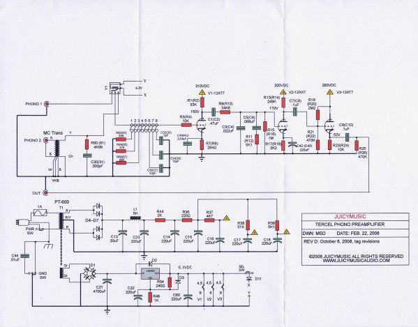
Well this is officially bizarre. I must have worked on one of your preamps in the past as I have a schematic called "Tercel". I have no idea where I got it from.
-
Cheap Forum Amp by Captainbeefheart
captainbeefheart replied to MEH Synergy's topic in Talkin' Tubes
I forgot about the slate grey, I think I like that a little better than the dolphin grey. Great choice on color!!! I don't like the viper green color at all but it's a little better than the original "Irish Green" I believe it was called. looks amazing! I have seen people swap over to Weber carbs but if I had that beauty I'd like to keep it original with the original Solex carbs. -
Ordered a Schiit Aegir (single) for my Cornwalls....
captainbeefheart replied to costerdock's topic in 2-Channel Home Audio
You can run the Aegir in mono mode with a 4 ohm load but you need to limit the current to 3 amps, that's around 12.6v into the 4 ohm load or half the available rail voltage in the amp. Basically just don't turn the volume up too far and the amp will be fine. -
It's not when bias is set to where it should be. These are fixed bias and when replacing power tubes one still needs to check where the bias is set and adjust accordingly. The original 275 has no adjustment pot, I don't remember if they added one to the mkiv but I don't think they did. Still not a problem, there are a couple resistors forming a divider circuit that you tweak to change bias. When the bias is set correctly the tubes do last a very long time, combine that with the fact the power tubes are under almost 100% negative feedback there isn't much of a point in "tube rolling" different brands because if the tubes are within their acceptable electrical parameters the feedback dissolves any slight sound differences between them. McIntosh didn't think it was necessary to add an adjustment pot because the tubes last so long. Any sound changes you might be hearing from changing power tubes cannot be directly related to the tube brand if you have not gone in and made certain you have the exact same bias between the them. The fact the bias isn't adjusted means you are more likely hearing a change in operating conditions (more/less bias current) and it's effects on how the amplifier functions vs brand of tube. Maybe I can get some posts approved today, probably not and nobody will ever read this lol.
-
who’s heard quicksilver horn mono amps?
captainbeefheart replied to edmjm's topic in 2-Channel Home Audio
The only thing that makes the amp "special" for efficient speakers is the extremely low sensitivity. It just passes the buck to the source which needs a substantial amount of signal swing (4.5v peak) to drive the amp. There are better ways to reducing noise while still keeping sensitivity at the point where normal sources (1v) will drive the amp to full power. As for the preamp meant to drive them, it uses a 12AT7 which is not the most linear tube since it's design was for HF/VHF frequency converter in radios. There are much better sounding tubes out there, why anyone would choose a 12AT7 is beyond me. -
Maybe You Have A Juicy Question?
captainbeefheart replied to RealMarkDeneen's topic in 2-Channel Home Audio
We can help until Mark returns from vacation. Most of the time I don't even print out a schematic when doing repairs/mods unless it's an extremely complex PCB with a lot going on like modern multi-channel home theater integrated amplifiers. In these s instances of course a schematic will certainly speed up the repair time. There are times when no schematic is obtainable and with something like a multi-channel home theater type amp, now the repair takes longer because I need to beep out traces/connections on the board to draw up my own schematic of the circuit in question. If you post some pics of inside the amp and boards then I can draw up a schematic.