ongtw75
-
Posts
8 -
Joined
-
Last visited
ongtw75's Achievements
Newbie (1/9)
2
Reputation
-
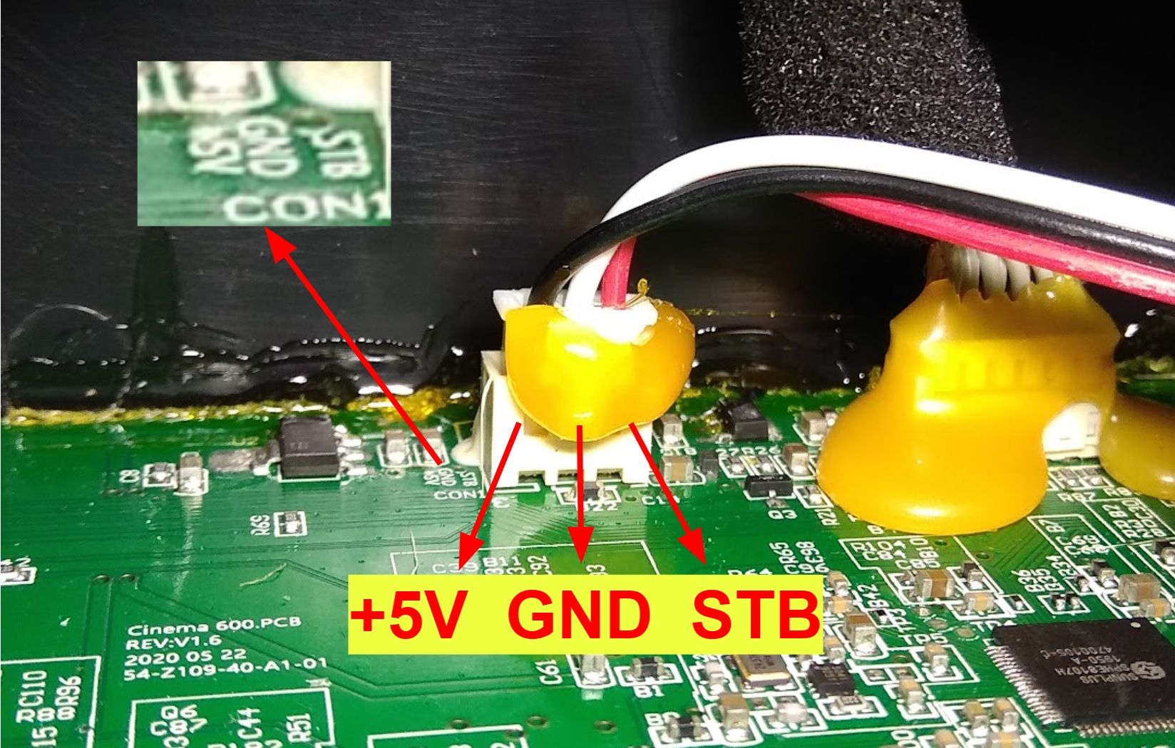
Hello everyone! Following on from my 1st post back in 3/10/2022, I've since fixed a few Cinema 600 power supply boards for other owners. They all had the same failure with capacitors C05 and C06. I replaced them with 220uF 16V part from NCC (Nippon Chemi-Con) KZE series. This is not a common size part. You may use 220uF 25V instead but it'll be a tight fit. As some others have noted here, the +5V and ground cable colors seem to deviate from set to set. For those having problem with their power units from Amazon, do trace the respective cables back to the amplifier board (left most connector) and wire them accordingly. I've attached a photo here for reference. STB need not be connected, it's only needed with the original power board. You can safely insulate it with electrical tape and tuck it away.

-
Hi, I'm from Singapore too and have helped a couple of owners fixed their Promedia 2.1 Bluetooth units. The thing about our local 230V version of this speaker is that it uses a different volume control circuit board and has an additional SMPS board within the subwoofer as compared to the US 120V version. Very often, the cause of failure (blinking blue LED light) is due to the faulty SMPS board, not due to the bluetooth chip being hijacked. You can look for me in Carousell should you need help in fixing it. Search for "promedia repair".
-
It looks like your set uses a completely different chipset and module for the bluetooth. From what I can see, there are 2 voltage regulator chips on onboard. 1 of them should be 5V and the other 3.3V, the latter is the power source for the bluetooth module. If you have a multimeter, you can probably trace the connection to 3.3V and disconnect it. Good luck!
-
Hi. You will need a power supply that outputs 24V and 5V. 12V will damage the digital/amplifier board. Cheers!
-
Well done! Thanks for the verification. Seems like this is a common weakness for this PSU, intentional or not.
-
R24 reads 220 (22R). As far as I can trace, the supply rails follow this sequence: SMPS 5V -> 3.3V VRM - > 1.8V VRM 5V -> ribbon cable that runs to the buttons, LED display panel and IR receiver. (far right side of the bar) The sound processor chip (DSP) and bluetooth module run off the 3.3V and 1.8V rails (they are always actively 'listening' in). SMPS 24V -> 15V VRM -> 5V VRM The class-D amplifiers run off the 24V and I believe the 15V rail as well (not verified). Not sure where the second 5V rail goes to, possibly to the wireless surround/subwoofer port. STB is pulled up to 3.3V but held low by the DSP in standby mode. It controls the enable signal to the 24V SMPS as well as both 15V/5V VRMs. I've also traced it to the ribbon cable. Hope the above helps! Please do correct my post if you have new discoveries. Thanks!
-
Hi minus0, the 24V section is controlled via the STB pin. Pull it up to 3.3 or 5V and the 24V smps will turn on. Under normal operating conditions, the sound processor chip controls this line when you press the power button. However if the processor isn't working (due to faulty 5V), then you will not see the 24V as well. Is the popped resistor R23 ? It reads 512 (5k1) on my board.
-
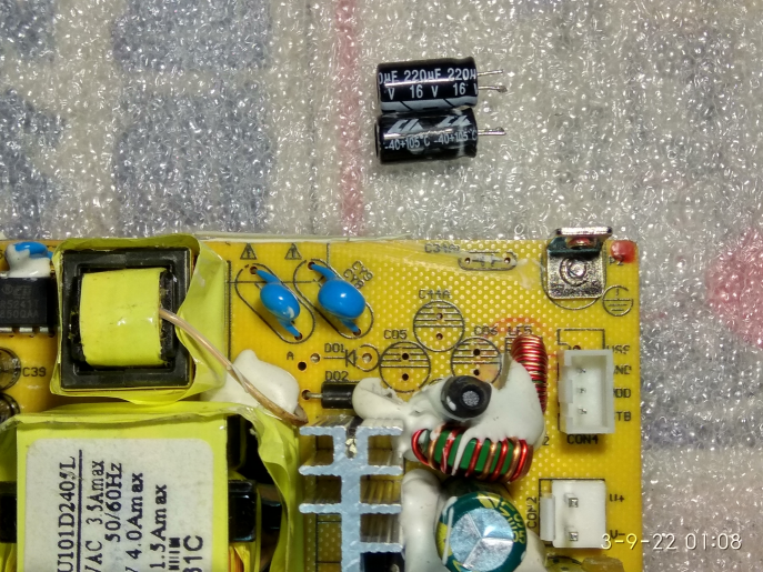
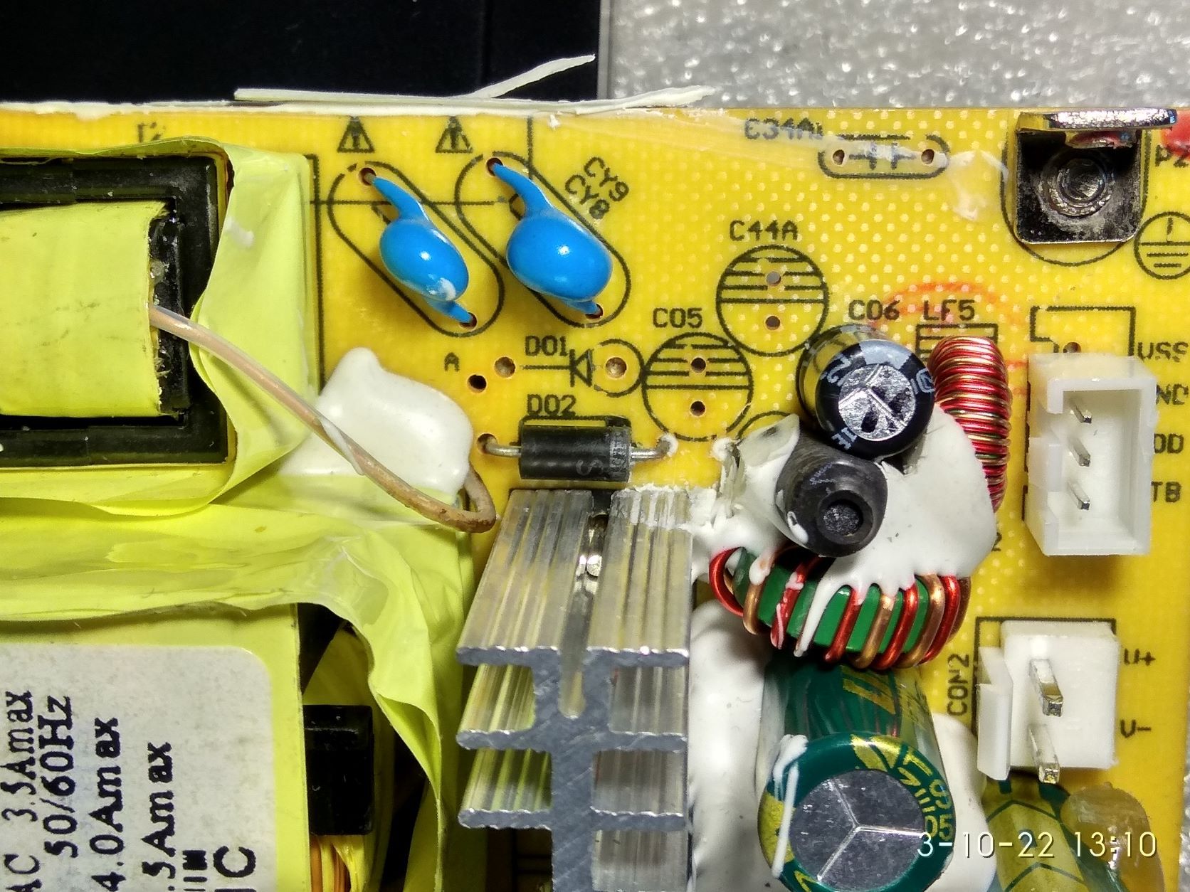
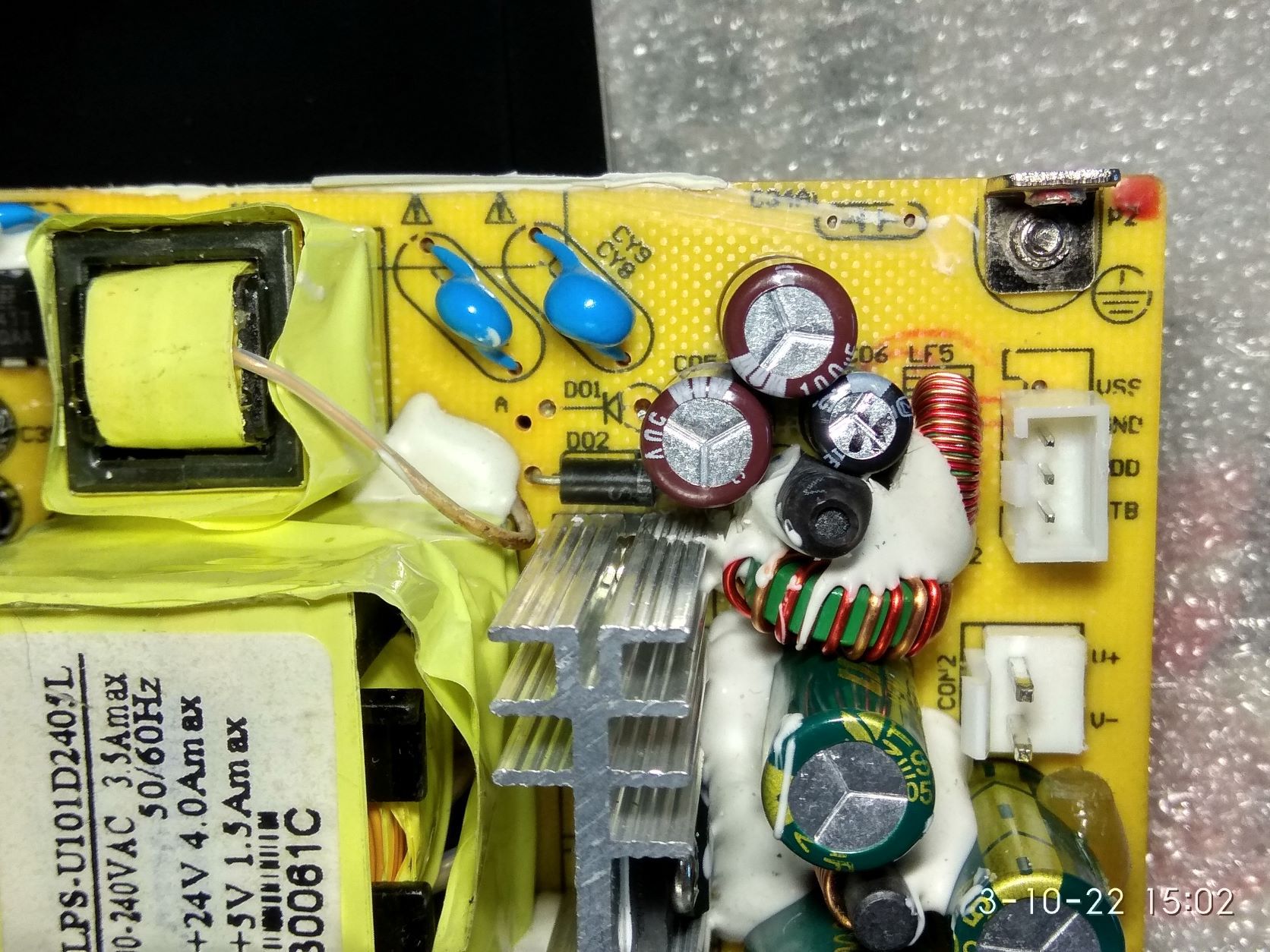
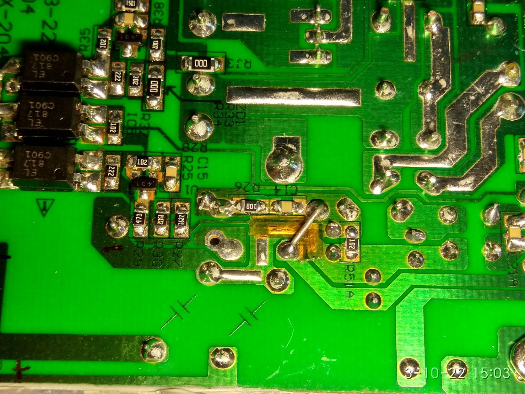
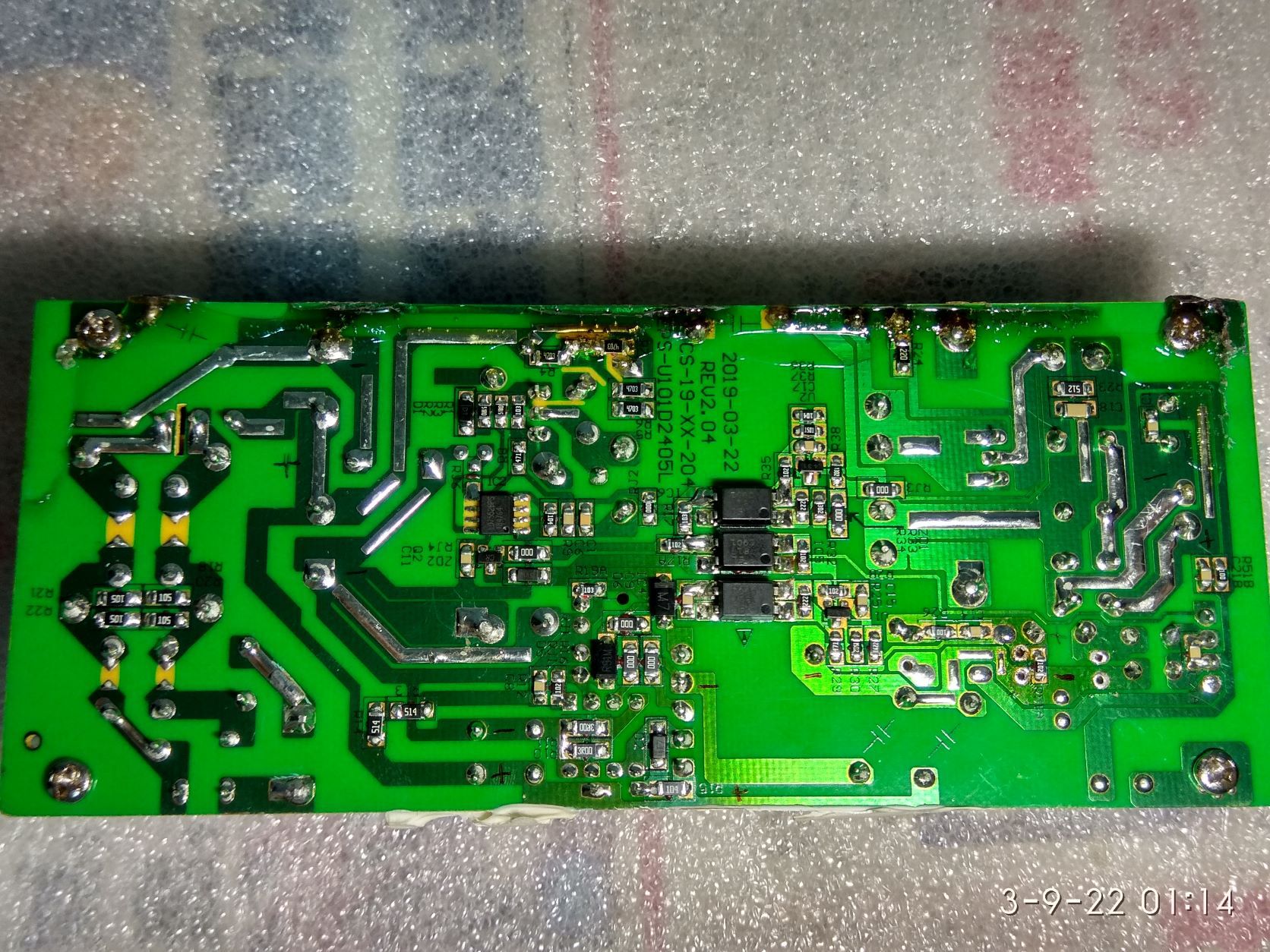
Hi everyone, I'm new to this community and recently found this thread on fixing the Bar 48. I'm a speaker repair hobbyist and recently a customer brought to me his Bar 48, complaining of no power. As SixerFixer has already written, the problem is related to the 5V output of the smps. Basically the smps could not sustain 5V when the sound processor chip is drawing current to power up the system, resulting in the voltage dipping to 2.7V. Thereafter the chip may sort of hangs itself and releases the drawing current, thereafter the voltage will rise back towards 5V. I've pin point the failure to be caused by C05 and C06, both being 220uF 16V electrolytic capacitors. There may not be any visible damage. For my case, 1 capacitor measured 169uF with ESR 0.4ohm, the other 30uF with ESR 4.5ohm. The latter part is closest to D02 (rectifying diode for this circuit). My initial fix was to replace the 2 capacitors with similar size and specifications type. The speaker did work properly however both capacitors were running very hot and it's only a matter of time before they will fail again. Without going much into technical discussion, basically the board requires very low ESR type capacitors to sustain a longer life span. My final fix is to replace C05 with 2x 100uF 50V (United Chemi-con KY series) capacitors soldered in parallel. This capacitor measures with ESR of about 0.17ohm. By connecting them in parallel, I effectively half the ESR but double the capacitance to 200uF (short of 20uF but still good enough). You may try purchasing a low ESR type capacitor of the same 220uF 16V, but I find it nearly impossible to have the right size that fits. I've also taken the opportunity to remove some of the silicon rubber glue surrounding D02 in order to give better cooling to that area. The extra capacitor is inserted onto C44A. The leads needed to be bent slightly to fit in the space. I've also deliberately mounted it in 'reverse polarity' with the aim of using the copper traces beneath for bridging. Below shows how the soldering was done. The yellow 'L' is kapton tape, to ensure no accidental bridging between those traces. The end result is that all the capacitors running cool to touch. I'll presume with cooler temperatures, this smps should last much longer than intended. Hope this info is useful for anyone out there. Cheers!