Erik Mandaville
-
Posts
4571 -
Joined
-
Last visited
Content Type
Forums
Events
Gallery
Everything posted by Erik Mandaville
-
Dynaco 60 wpc stereo tube amp kit
Erik Mandaville replied to Nailbender's topic in 2-Channel Home Audio
The above is one of the later versions I built, which includes a small filter on the output. Some seem to have adverse reactions in the presence of electrolytic capacitors, but please note that those used in this circuit are appropriate for the application. I found a more simple crossover, such as the type 'A' for example, to work better than a higher order design with this amp. Again, it's subjective. The Transcendent Grounded Grid preamp is also a great performer for the money, and I've built several of those -- a few hours work after you have some practice. The circuit design was historically more common in the RF field, and Rozenblit found a good use for it for music audio. Very quiet, too. Have fun, Erik edit: Just to mention because I think it's important to know: The SE OTL is even better IMO when setup as a monoblock. Quiet grounding can be kind of a juggling act at times, and I found the 4 watt monoblock-wired SE OTL quieter than the stereo counterpart. With efficient horns, the sound is just outstanding. Output transformers are kind of like passive crossovers in some respects: sort of necessary evils. OTL amps and active networks can be the answer to those problems for some. -
Dynaco 60 wpc stereo tube amp kit
Erik Mandaville replied to Nailbender's topic in 2-Channel Home Audio
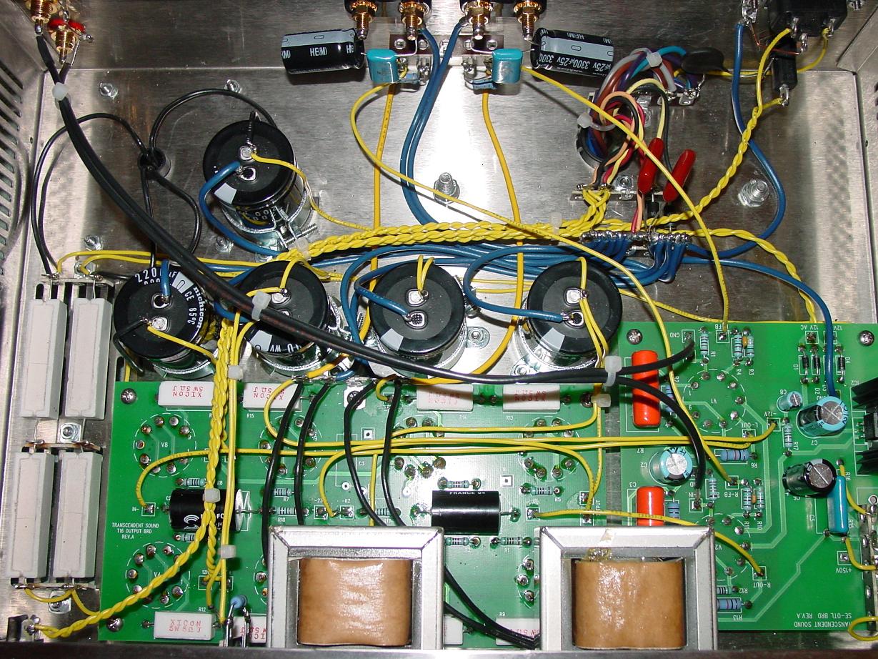
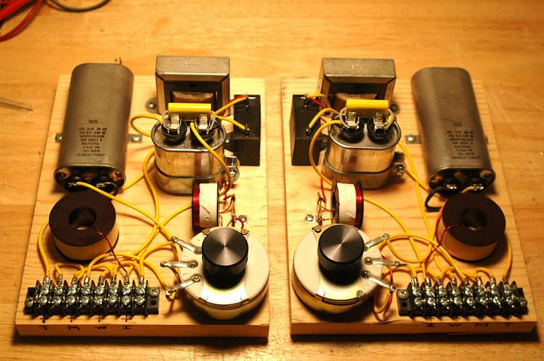
Here's what's in the SE OTL: Each socket has to be soldered, pin-by-pin into the circuit board sockets, as well as the other parts stuffed into the boards. The rest is point-to-point, with some cap/resistor bypass connections that are just a little bit fine.
-
Dynaco 60 wpc stereo tube amp kit
Erik Mandaville replied to Nailbender's topic in 2-Channel Home Audio
You might also: Check the menu on the left at www.tubesandmore.com for kits. There is a link to an actually quite well-reviewed stereo amp kit for under $200. While kind of expensive as a practice, just something else to look at for interest, and there are lots of interesting things there to check out -- tubes, transformers, sockets, other passive/active parts. The kit is built on PCB, and mounted on a board. Shawn is talking about the Transcendent Sound SE OTL as seen below. It is an incredible amp for very efficient speakers, but 1.5watt/channel might leave some wanting for more. I loved it. edit: Forgot the laptop doesn't have the pictures on it. I'll post a couple later. The instructions are easy to follow, as well. The Transcendent T-16 with more horsepower was as quiet and equally superb. Erik -
Dynaco 60 wpc stereo tube amp kit
Erik Mandaville replied to Nailbender's topic in 2-Channel Home Audio
I think it's great your even willing to consider building for yourself. For many, the learning (including making mistakes) is easily worth the investment, and for others not. Each to his or her own as far as values in that respect. These have always looked like neat kits to me, and I thought I would leave the link just to check out. MANY people have done modifications to the famous ST-70, and I know of those who have done some of the modifications only to find they preferred the sound of the original. I've heard a couple of different takes on the circuit myself, and I think the original is still a really good design despite what others may say. I have the ability to carry out any of the available modifications, and I'm happy with the stock circuit -- At least for today! Again totally subjective. Here's the ebay listing for Triode-Electronics: http://cgi.ebay.com/Triode-Electronics-ST70-Dynaco-ST-70-DIY-Tube-Amp-Kit_W0QQitemZ380044579282QQihZ025QQcategoryZ50593QQtcZphotoQQcmdZViewItem Erik -
Actually, I've forgetten that I have already made this very network. It's the one I'm using now, but with a fixed L-pad rather than the autoformer. No matter, I'll make it anyway. You'll note that the tweeter branch will use the values posted by DJK (as well as me according to my own schematic), and the midrange branch will be done as Bob had done the type 'A' with the choke between the autoformer and squawker. I just have to use a slightly different value choke because of the lower crossover point. This is a straightforward modification.
-
I have the type AA modified for 4000Hz on paper, and will wire the midrange branch with the 13 uf cap and autoformer the same way he has done with the type 'A.' That's one part of this design I continue to ponder. In any event, I have the needed capacitors, autoformers, and two chokes. The chokes are only slightly lower than what's needed, and I can add a few turns of magnet wire to reach the needed inductance. The tweeter part as outlined above is pretty easy, though. Who knows, maybe this will sound good enough to convert me back to Autoformerism. Erik
-
4kHz Butterworth for the type AA: 1) Keeping everything else connected as shown on the schematic for this first part, you can remove the tweeter section from its connection point after the 13uf input capacitor. 2) Adding lead length if necessary, connect the wire you just removed from the downstream side of 13uf cap (where it connects to the autoformer) and reconnect it to the positive input to the crossover (or just to the opposite end of the cap -- either way it's the same). 3) Add 1.5uf in parallel with the first 2uf capacitor, and add 8uf in parallel with the second 2uf capacitor. (This may actually lower ESR, and possibly make a difference you can hear) This is for the tweeter section. Any takers on the squawker branch? A change needs to be made there, as well.
-
"I just want to do it the way it sounds best." Maybe the way it is will do just fine, but I would defer to Bob in terms of what he's done with this while maintaining the autoformer as an essential part of the design. BTW: You could also convert to an 'A' and just use a single first order series cap on the tweeter that gives you the desired reactance at 4kHz or 4.5Hz. The suggested crossover for this tweeter is, if I remember right, 3rd order at 3.5kHz, so if crossing at 4000, it still might be better to use a sharper cut-off than what you get with 6dB/octave.
-
Since the tweeter is run wide-open, you can treat it as a separate entity, connecting as mentioned above directly to the amp input. However, if you wire a true bandpass, the values chosen need to reflect not only the low-pass crossover point, but for the high-pass, too. So some adjustment is needed, but it's not difficult. The autoformer adds a little oddness, though, because of the reflected load impedance concerns. Erik
-
My own is a 4KHz 3.5uf - .24mH - 9.5uf Butterworth on the tweeter. Narrow bandpass - (neg) 2dB 16 ohm L-pad (fixed) on the squawker (no autoformer) The first experiment was an even-order design using 5uf in series with the tweeter and .57uf and 28uf (approx) in the bandpass. I also made a second order reverse polarity design, and prefer the mixed order network using the 3rd order filter on the tweeter. Erik
-
"OK, so what do I have to alter on my AAs to change the crossover to 4K?" Bob has worked out a 4.5K crossover for the new tweeter, which is only 5 kilocycles 'faster' than the one I made. Dee sent me those networks to try along with the new tweeters for a first audition, and I liked what I heard very much. Actually, maybe they were type 'As' (?) -- I can't recall.
-
Dee: Absolutely. I've been aware of the availability of the driver, but the integration with the new horn is what is so nice. I have wanted to maintain the overall appearance of the Klipschorns, and what Bob worked out fits perfectly in that respect. As we've mentioned in the past, too, the lower crossover plus band-pass in the midrange is an important part of the modification -- IMO. Erik
-
I recieved our third CT 125 for a center channel upgrade, and once again was impressed with the quality of the horn Bob developed. The other two in the Klipschorns, with a lower crossover point of 4kHz, have provided much needed HF extension and presence, and this last one will allow for better matching between the three front speakers of our HT/music system. Thanks, Erik
-
Khorn AA crossover mods...??
Erik Mandaville replied to twinbugles's topic in Technical/Restorations
" You want to have tweeter protection, even with low power. " I agree, and would add too that low power when pushed into clipping distortion is more often a cause of tweeter failure than clean high power. Good luck on your SET project! Erik -
Advice on new Caps for AL crossover
Erik Mandaville replied to kg4guy's topic in Technical/Restorations
I'll get those parts off to you as soon as I find a box! I think I have a couple of 2uf caps around here, but the autoformers and the chokes for the woofer are set to go. The type 'A' is a snap to build, and to me sounded much more open after I compared it to the AL (which I had liked at first, but which I quickly learned sounded very closed-in and 'dense' compared to the more simple 'A.' Erik -
It's neat to see additional interest in this! As Shawn mentioned, the Lexicon will work really well for this and provide a great amount of flexibility and fine tuning. I built PWK's 'minibox' center channel box a few years ago just on a whim one early Saturday morning, and it changed the way I listen to music. The addition of a third derived center channel was far and away the most significant updgrade I had ever made, and it cost me nothing. Shawn let me borrow a slightly older model Lexicon to help me learn what's actually possible with surround sound, and we purchased our own shortly after. Two-channel listening still sounds good to me, although I find it less natural and realistic than our carefully tuned 5.1 Klipschorn, Heresy, SVS, system. Some claimed that it is simply sitting in the middle of the combined crosshairs of five loudspeakers, and that description couldn't be more inaccurate. The sense of subtle envelopment and acoustic space can be pretty amazing. There are times I wish I hadn't sold our La Scalas in order to use three identical speakers for the front stage, but the Klipschorns and Heresies are not bad at all, and seem to work better here in terms of domestic compromise with audio and room decor. Have Fun! Erik
-
Heresy Crossover Mod - Less Bright
Erik Mandaville replied to JohnA's topic in Technical/Restorations
"It also robs efficiency by increasing insertion loss -- almost 3dB. I have a Dope from Hope on that at work. Maybe Bob will save me the trouble and post it." I would rather you post the schematic of your passive Jubliee crossover. Erik -
Heresy Crossover Mod - Less Bright
Erik Mandaville replied to JohnA's topic in Technical/Restorations
"The basic issue for PWK is that resistors get in the way of the driver seeing the low output impedance of the amp." PWK's ideas behind the use of the autoformer have been published here on many occasions, but the link provided will be helpful for those who might be interested. I've experimented with all approaches to attenuation mentioned here -- autoformers and fixed and variable L-pads -- and find that resistive attenuation in no way degrades performance. I'm sure you're aware that many very well known and highly regarded speaker manufacturers (Altec was one mentioned above) used resistive L-pads. PWK didn't care for them, and I both understand and respect why. There are those on this forum who have made far more drastic changes to his original designs -- new horn lenses, new drivers -- that doubtless would have much greater impact on the sonic presentation of the original design than simply using a different means of reducing gain in one or more drivers. I suspect that if an autoformer had such a clear advantage over a resistor, and that what they contributed to the sound of the speaker was a significant element in the design criteria, they would continue to be used today. As far as I know (please correct me if I'm wrong), the autoformer is no longer used. If variable L-pads were so inferior, why do so many other well-known brands, both in the professional and domestic worlds, make frequent use of them? Again, each of us is free to use what works best, and that is why I proposed another means of even finer gain adjustment ability. BTW: the main driver in question above is the tweeter, which as I said can be separated from the autoformer and connected directly to the input of the network through a slightly larger capacitor, and an L-pad installed on the driver. I have done it many, many times over the past 20 years, and it provides not only entirely acceptable performance, but a much finer and directly comparable type of control, IMO, than an autoformer. Again, we have the freedom to choose, and that choice, IMO, does not have to be influenced by anyone other than ourselves. Erik -
Heresy Crossover Mod - Less Bright
Erik Mandaville replied to JohnA's topic in Technical/Restorations
And lastly: Bob Crites offers very good quality autoformers with a greater number of steps of attenuation. We have an early pair of Heresies that I used his replacement autoformers for, and I'm keeping these entirely stock in terms of crossover design. I'm mentioning this in case you can't quite find what you need with the stock autoformer, which has 'courser' steps between taps. The center channel I'm building will have variable L-pads for both the 4kHz tweeter and bandpass squawker. Erik -
Heresy Crossover Mod - Less Bright
Erik Mandaville replied to JohnA's topic in Technical/Restorations
"ll try moving the tap. The K-77 looks (as posted) and sounds, real hot. 3dB would sure help though. I'll post back with that. In the long run, a new crossover designed with a bandpass mid with crossover points selected to compliment horn directivity in the vertical and horizontal dimensions, (something else I'm learning about....), if possible, would be fun to try after I get better measuring abilities. And there are the other projects which never get done. The 2 way Econowave over at AK has to get done first. " The Econowave project looks interesting, Skywave R. A true bandpass with this driver is not difficult to do, as you seem to understand. Just as there are minimal passive parts in conjunction with the mid and HF drivers in the Klipsch E and A networks (again, for example), so does a first order bandpass for the midrange require only two: an inductor and capacitor in series, the values of which are determined by the upper and lower crossover points. The autoformer is just one way of attenuating a speaker; the more common approach as is even mentioned over at the AK site in relation to the Econowave project, is to use a resistive L-pad. I hope someone will correct me if I'm wrong, but it's been my understanding that the current Heritage networks no longer use the autoformer. If so, that's neither a negative nor a positive thing. A Jubilee passive design that's shown up here in the past also uses a single fixed resistor of a few ohms. They work, and do not in my experience, degrade the sound. One should of course use whatever one feels most comfortable using, though. For your Heresy, if you didn't mind making a slight modifcation to the back panel (which you may not want to do), it would be very easy to install an 8 ohm variable L-pad for the tweeter as I mentioned above. You seem comfortable with the balance between the midrange and woofer, and thus it would work fine to take the tweeter off it's connection to the autoformer and instead connect directly to the input. It does not need to have to be associated with the input capacitor between the amp input and autoformer in order to work properly. However, if I remember right, the capacitance needed for 8ohms and 6000 Hz is just over 3 uf, so to maintain the crossover point, you would need to bypass the 2uf now being used with another cap. If you wanted to do this, I have two nearly new 3uf caps (Solen) you can have. I probably have a couple of .22 or .33 uf caps I can solder in parallel with them. The L-pad, which is technically not really part of the crossover, is inserted between this crossover and driver terminals (which I'm sure you already know). You would need to drill a hole of about 1" in the center of the cabinet back, probably close to the top. The L-pad can in turn be mounted on a small piece of masonite with a hole drilled in it for the shaft. The mounted L-pad shaft is inserted through the hole in the back of the cabinet until the masonite or acrylic plastic or plywood (which you chose to use) is flush againt the inside back of the panel. It can be glued in place with silicone rubber and set to dry overnight. A knob is attached to the L-pad shaft, and you can then adjust on the fly until you get the balance the way you want it. If you have a good idea of the actual drop in dBs you want, you can even experiment with a fixed L-pad. ...Or, of course stick with the autoformer and experiment with that! I only mention the above as something you can try. I played around with a 12dB/octave/reverse polarity filter with my Klipchorns for awhile, and in that case just installed the variable pad on the crossover board itself -- easy to adjust since the back of the Klipschorns is easy to get to. See below. With a 1.5 watt OTL amp the results were not pleasing, but with higher horsepower it worked fine. Good Luck!
-
Heresy Crossover Mod - Less Bright
Erik Mandaville replied to JohnA's topic in Technical/Restorations
"I'm not saying it can't be done.." That's good, because it can be done and isn't very difficult to do. Erik -
Heresy Crossover Mod - Less Bright
Erik Mandaville replied to JohnA's topic in Technical/Restorations
I'm not kidding in the least. What do you see in the way of impedance equalization circuits or resonant peak and notch filters in, for example, a type A Heritage network? It's entirely possible to create a network that not only works as well as the 'A,' but arguably better. What 'special provisions' were made in the type A? As far as I can tell, not any in terms of corrective circuits. What was used to design it was based on the same parameters I used to make my own -- driver impedance and desired crossover frequency. Right. Resistors do dissipate heat, and we know that the late Paul Klipsch was opposed to them and chose to attenuate by way, at least in the example of the type 'A' I'm using, of intentional impedance mis-matching. It's not just MY L-pad, BTW. The majority of well-known speaker makers that provide a means of user-ability and preference in terms of balancing driver outputs use adjustable L-pads. It's not only slightly easier than altering outputs on a multi-tapped choke, but much, much easier. In your view, is it easier to turn a knob to adjust gain, or shut down the system, take off the back panel, unsolder-reposition-and-resolder autoformer connects, and then alter values of necessary capacitance to compensate for the resulting reflected impedance, and then put the back panel back on, power up the system, and then listen again -- perhaps only to find the the change made on the autoformer was too course, resulting in too much attenuation or gain. I've done both, and find that turning a knob much more straightforward. In other words, a 3 dB drop in output will be a 3dB reduction regardless of whether an autoformer or resistor (or pair of resistors or a variable L-pad) is used as the tool. I would just rather do it while listening to the result, and prefer the far finer control of a variable L-pad. Erik -
Heresy Crossover Mod - Less Bright
Erik Mandaville replied to JohnA's topic in Technical/Restorations
And if the squawker output is too great once the tweeter has been attenuated, a variable pot can be used there, too. I'm doing this very thing with the Heresy center channel I've been gathering parts for. I just have to wind the coils and find a woofer somewhere.... Erik -
Heresy Crossover Mod - Less Bright
Erik Mandaville replied to JohnA's topic in Technical/Restorations
A more common and widely accepted (e.g. Altec, JBL, other well-known companies -- including Klipsch) way of going about the business of driver attenuation and balancing is to use variable L-pads. If nothing else, it reduces the potential for confusion in dealing with the impedance variations and ramifications associated with the autoformer. The tweeter (and squawker for that matter) can be removed from the autoformer and connected directly to the input of the amplifier by way of values of capacitance chosen for the impedance of the driver itself and the desired crossover point. Since the behavior of the drivers in question is well-known, the calculations are straight forward. I found an improvement in performance of the squawker by designing a true band-pass with resistive attenuation. Something interesting to consider, though: What is the order of tweeter filter? a 6dB/octave roll-off has been indicated many times. What, though, is the value of required capacitance for 1st order 6kHz network with an 8ohm tweeter? The answer to this question isn't found in the original schematic, and that has certain implications. What are those? An easy way to reduce tweeter output is to disconnect it from the autoformer; slightly increase the capacitance in series with it; and install an 8ohm variable L-pad just ahead of the driver. That will provide a constant 8ohm load regardless of the level of attenuation, as well as maintain the 6kHz crossover point (or lower if using a tweeter that can handle it). Bob's tweeter setup works very well with a 4kHz third order network. Just adjust the output to the desired balance in relation to the other drivers. Much finer adjustment and tuning is available through the use of a pot here. Erik -
Another Heresy II crossover rebuild
Erik Mandaville replied to kg4guy's topic in Technical/Restorations
As always, a great of example of what a little practice and DIYing can do. Erik