
John Warren
-
Posts
2257 -
Joined
-
Last visited
-
Days Won
1
Content Type
Forums
Events
Gallery
Everything posted by John Warren
-
Sovteks have been available for some time. Purchased 4 5AR4s, 10 12AX7s earlier this year. Just purchased a quad of EL84Ms too, supplier as 90+ is stock. So much for the Russian import ban.
-
On the rectifier replacement, the 12AX7 filament string should read ~ -72VDC without tubes and with all four plugged in drop to -55VDC. If one tube socket is dodgy the whole string is out of commission and none will light, they're in series. It's not uncommon to have the original 12AX7s in these amps, they last forever. They were shipped with Telefunken. That got a chuckle out of me!
-
The first place to start, assuming the power supply transformer is ok. is to pull all the tubes and go after the three electrolytic multicaps, all three need to be replaced with either replacements (Hayseed Hamfest does a nice job) or discrete assembilies under the chassis. Don't bother "reforming" or some other foolish thing. One must first get all the DC rails up to snuff. Replace all the carbons with ceramic compositions then get rid of the selenium rectifier. These amplifiers are very straightforward to service but can also be a ticket to an early grave so ground your chassis and check the fuse first before you go in. Updated link. Scott 222C (ipage.com)
-
This was common given that most manufacturers would just fold a long sheet of glass and stuff it into the enclosure. You should have left the glass in, much, much superior to the plastic crap.
-
"Before I tell you about the sound..." The starting line of the snake-oil salesman.
-
Another vintage classic for service. Will document in the page below for those of you interested in this sort of thing. The interior wiring appears to be factory virgin, i.e. no one was ever in there. It's a wee bit dirty and the multi caps, the selenium rectifier are shot so first thing is to get the power supply proper. The power supply transformer is good. Scott 222C (ipage.com)
-
Thank you.
-
Capacitance changes with changes in frequency, voltage, humidity and temperature between the two "film" types are significant. Companies like WIMA, KEMET, Vishay and many others have factories dedicated to the fabrication of either polyester or polypropylene film caps. There's manuals, application and usage guidelines specific to each type. The selection of the wrong film in many applications (power supplies as one example) will determine the failure rate. The point being, it really does matter.
-
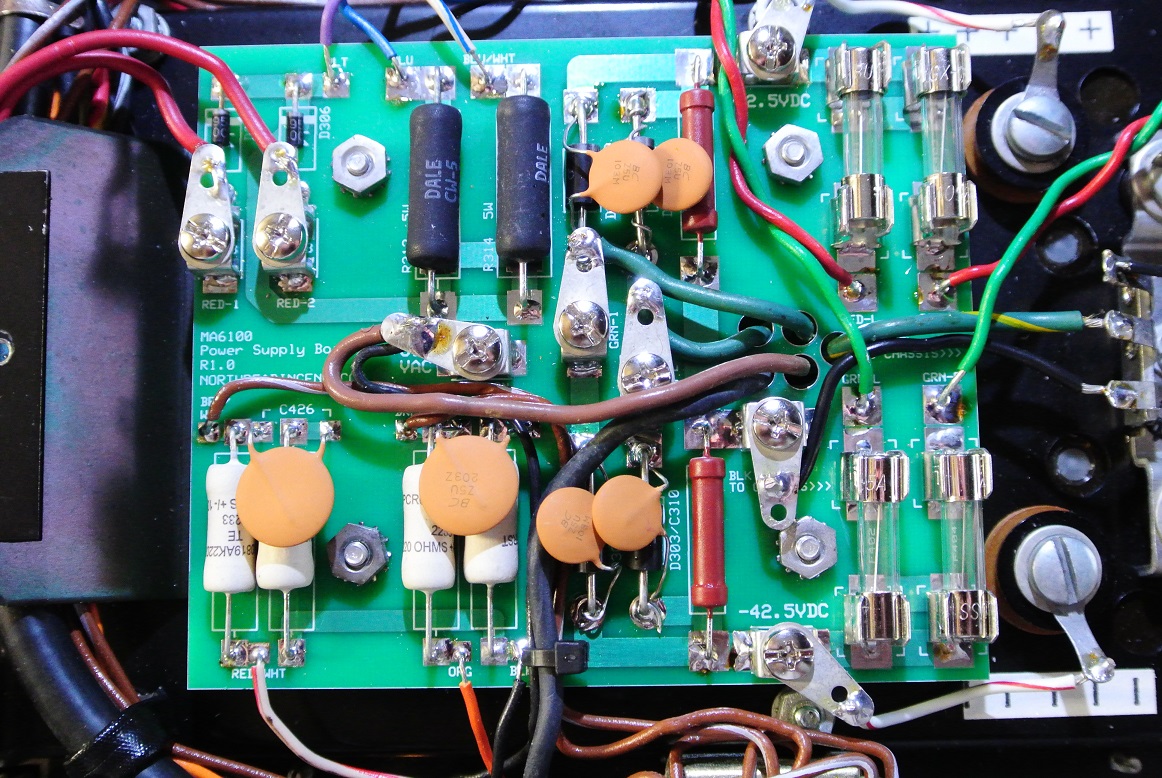
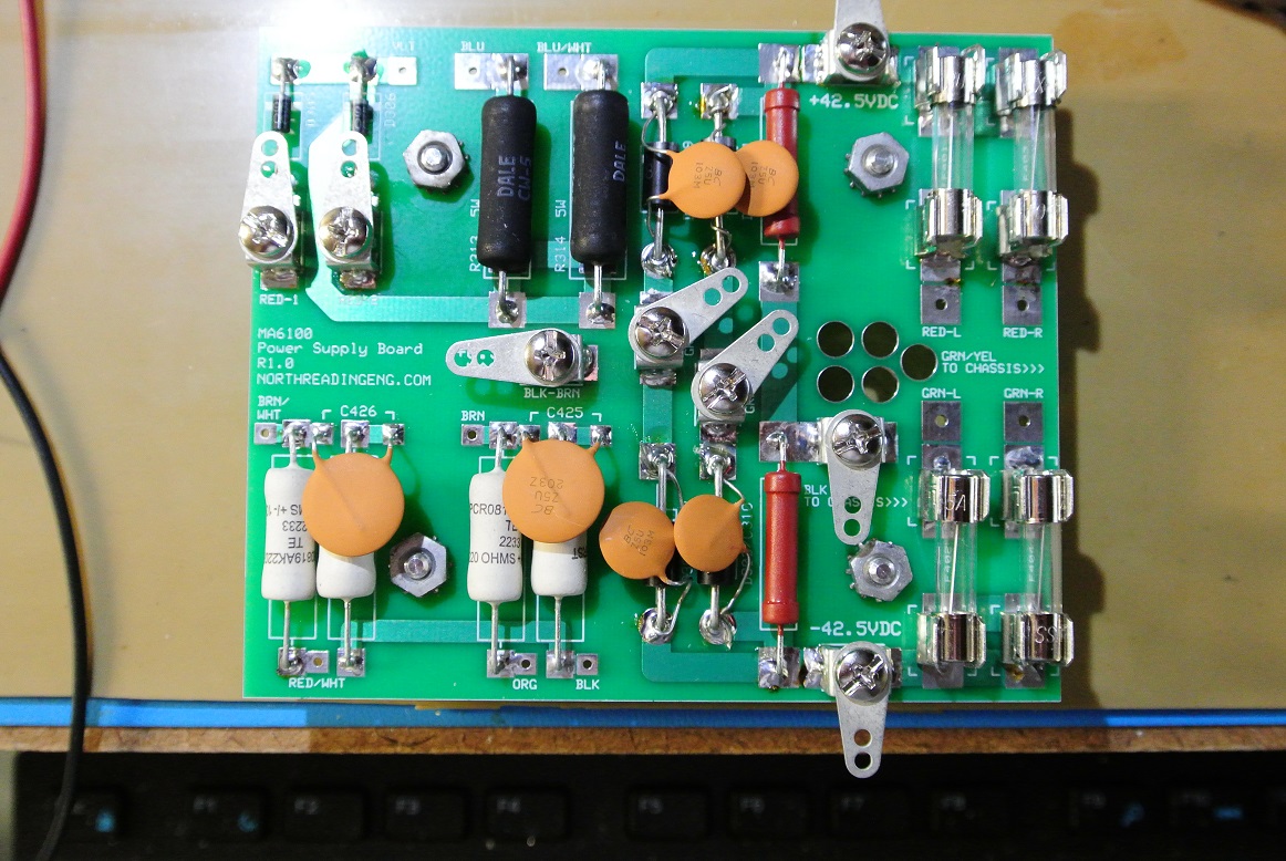
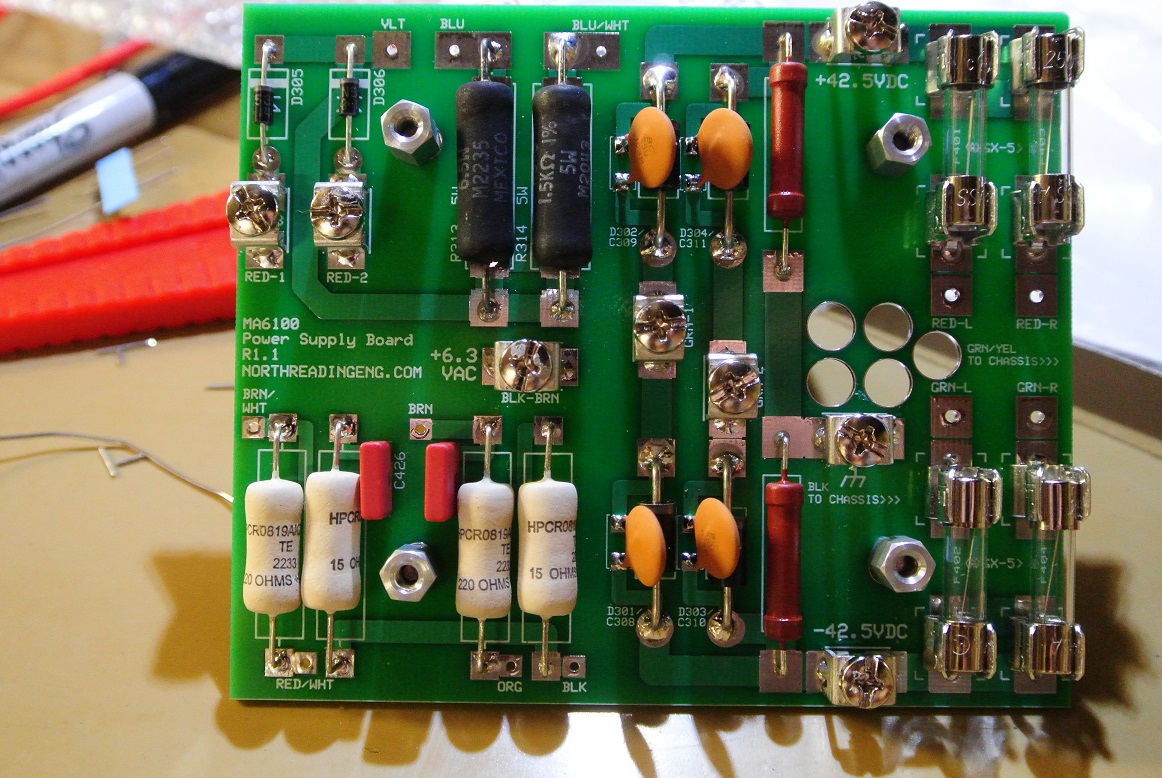
Here's the revised design (R1.1). A bit tidier. The caps can be ceramic disk of film type. Caps across rectifiers should be either ceramic disk or polypropylene. I kept the ceramic disks because I have them. If they're film, the must be polypropylene given the application. It's a significantly better dielectric than polyester, far better insulation and dielectric behavior. The board will accommodate a WIMA PCM5 AC pulse type. For the output stage RC filter a WIMA general purpose polyester (PET) is ok and what's installed. It's also in the PCM5/7.5mm package replacing the ceramic disk (easier to install and I have them). Polyester caps are fine for decoupling and noise suppression and they're low cost. They pick up moisture and that changes the behavior as a function of frequency. They have rates about 40X higher than polypropylene. As a general rule you can replace polyester with polypropylene but not the other way around.

-
Awesome, thanks! Next questions, how can this relatively simple design be improved? There are a few modifications that can be made but there's also space constraints. That requires going to the simulator. Will detail that on the forum below. MA6100 Power Supply Board (northreadingeng.com)
-
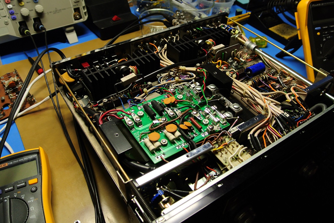
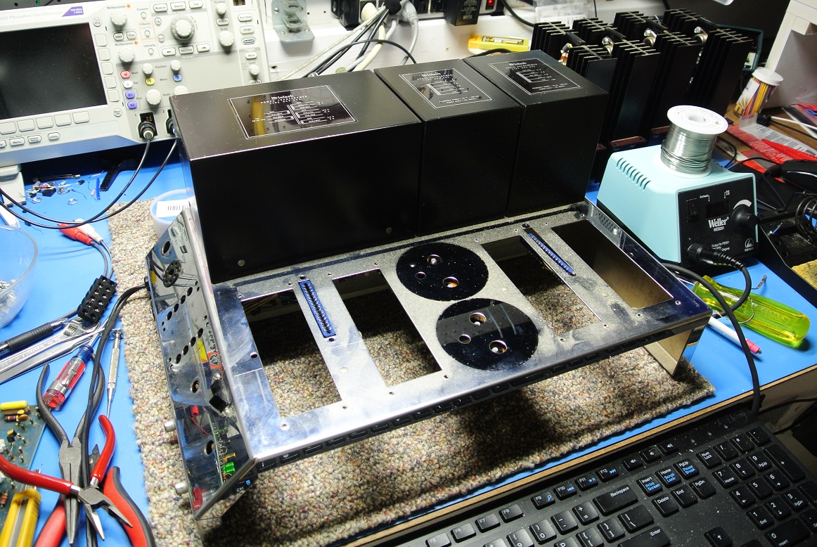
Thank you. On the difficulty scale this board is a fairly straightforward effort. I also have a few design tools that help in identifying trouble spots before I commit funds to board production. I do have a second iteration of the board designed but will wait until I have another 6100 in for service before ordering it. One more photo of the installation:
-
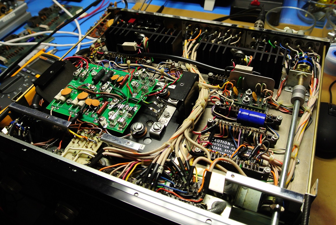
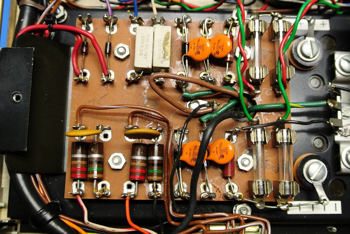
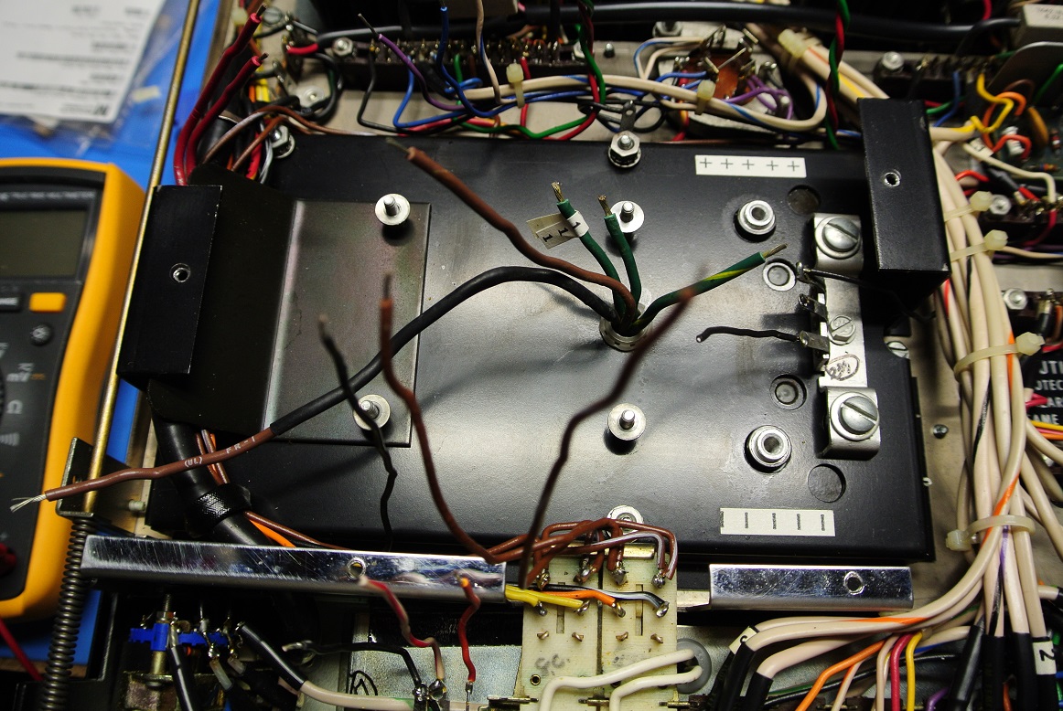
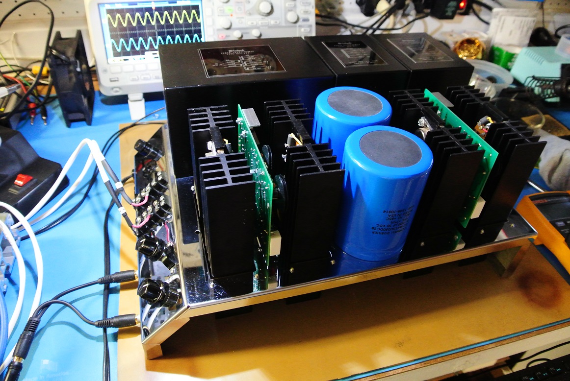
This was a cool project. Gent purchases an MA6100 from an estate sale. The amp is new, never used, still wrapped in plastic bag but it's missing the power supply board. So he needs a board and contacts me. I do not have these boards just lying around. There's two ways to solve this, buy a "donor" amplifier and hope it has a good board or design a new one. When he sent me an email, I intially said I wasn't interested. We chatted a bit more and I decided to do it and, as it turns out, wasn't really that difficult. Since I too own a 6100 I decided to design a board for my unit and his. So here's the factory original: And the replacement: Board pulled from the amplifier: Board ready for install:
-
Maybe You Have A Juicy Question?
John Warren replied to RealMarkDeneen's topic in 2-Channel Home Audio
I've serviced a Peach II, specifically the filament section that provides AC-DC conversion to source VDC to the small signal heaters. In my case, this was a relatively straightforward effort, a few hours. If your unit stops working and the tubes (except the rectifier) are cold, it may be the power supply sourcing to the filaments. Also, the filaments are in parallel so if two are bright and one dead, suspect the tube, the curcuit is ok. I've documented the servicing here. Juicy Music Peach II Preamp (northreadingeng.com) -
Significant experience.
-
Good question. The solid-state amps today are vastly more complex than the first-generation units. Their business model is primarily selling new, solid-state amps. Having a revised solid-state design (a few op-amps and tweaks) that's basically 50+ years old sound as good as the hardware they make today would be a marketing nightmare. The "sweet sound" of a hand-full of transistors vs. 2000+ transistors is said by no one. It would be problematic, contradictory. And thank you!
-
Thank you Gents! This unit went to a customer in Kentucky.
-
Why buy a Mc 275 when you can have one of these!
John Warren replied to michaelwjones's topic in Talkin' Tubes
The rule of law is a Western idea. -
Told you so. The lettering is fine too.
-
Nice of you to say, thank you!
-
The Music Box, Wellesley--seeking information
John Warren replied to Rivendell61's topic in Ask the Historian
Purchased a few items there including a pair of decorator Klipschorns. Great times, long, long ago. -
Electrolytics age while under load. The life expectancy of an electrolytic (say 4000h) is based on it operating typically at 2x its max. continuous ripple current and max temperature (usually 105C). Temperature is the big driver. Most electrolytics are rated to 105C max (220F) which is quite hot and sitting at that temperature with no power will shorten life. In real world circuits, electrolytics rarely exceed 40C and, at design ripple current, will last much, much longer.
-
Why is this topic in solid state?
-
Thank you! I made four amps and sold three. It would be good if it had a wood-grained base that would make it aesthetically pleasing. Might make it easier to sell too. I can fabricate one if necessary.
-
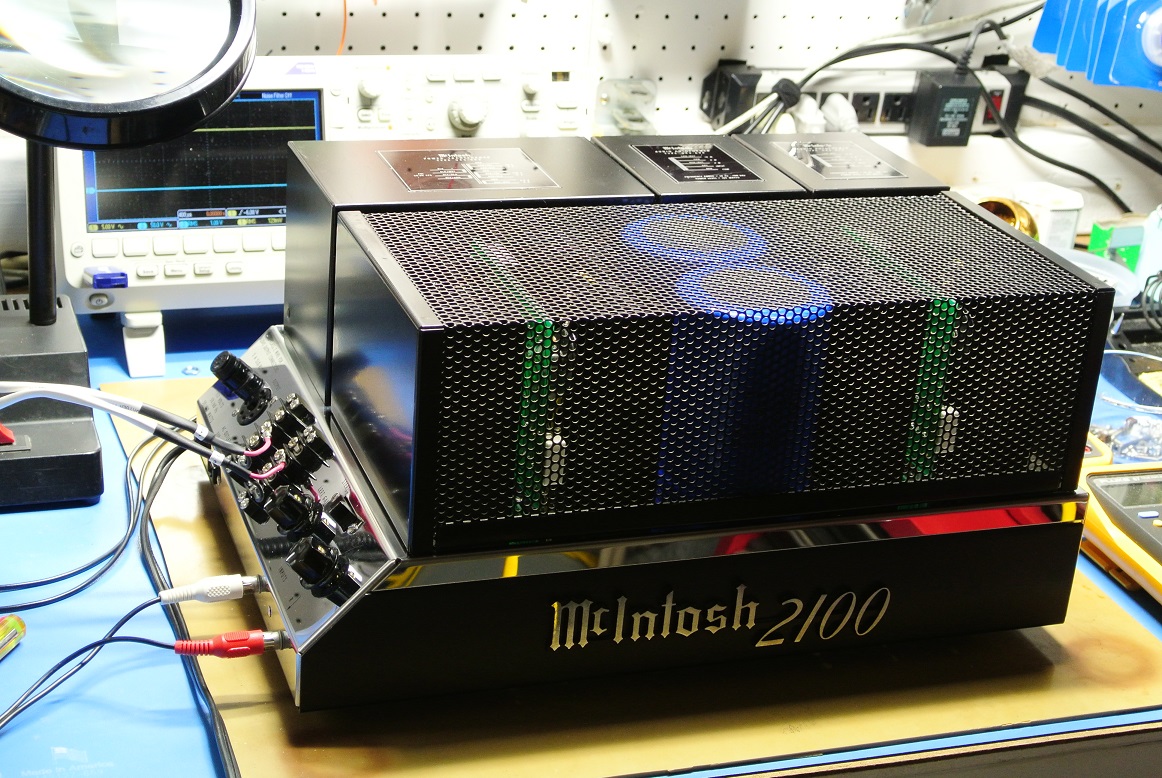
Good to hear! I took a year or so off servicing the old McIntosh hardware, tube and solid state to focus on the day job (which is also more engineering). In my little world, getting to a point where I'll soon retire from all day jobs to focus on other things (getting old!) and going into retirement spending time working audio hardware has lots of appeal. Good health into your 60s and 70s is the exception not to be taken for granted and extreme stress (like working in an engineering startup as a key contributor) debits health and beats up the immune system. Sure, you can eat right like low carb. exercise and maintain a 23 BMI but the termites and Maxwell Demons are always nearby. The amp I'm working on in the link above was missing a few parts, the owner wants it restored to "like new" condition. I have some pretty scarce parts on hand including autotransfomers, power supply transformers, meters and even two 2100 stainless chassis, all in basically like new condition. I managed to obtain this hardware whilst working at a McIntosh service facility in the late 70s!!! There's also a method that allows the chassis to be polished to a mirror finish without taking the lettering off. It's a secret.