ClaudeJ1 Posted November 17, 2010 Share Posted November 17, 2010 I'm about to build a tapped horn for my lone LAB woofer 30x60x14.5 inches.. I already have cut pieces for 2 original Danley LAB horns to replace my MWMs in my stacks, but no funds for the 3 extra drivers I need (bought Heresy's and Fortes for other rooms instead) so that will be on hold until 2011. the tapped horn is from the DIY forum on the Tapped Horn project and uses only one LAB 12 woofer per box.. Field proven to go lower (like 16.5 Hz) than the Tuba in a 15 cu ft. box, but lower efficiency.Mine will be an oak coffee table. Only need 2 sheets of oak plywood. As much as I would like to get started on either the tapped horn or the TUBA HT, the wife has her(our) kitchen in the project list before the home theater stuff so I am hold a bit as well... From what you say above the single 12 tapped horn has been built by others, do you have some direct reports of the build and end results? Is the single driver version you are planning to build the one you posted the plan for? Also you mention that you were going to make a pair of Danley LAB horns, even have to wood cut, are these plans available? I was reading where the driver used in the Danley had significantly different electromagnetic parameters then the Eminence LAB 12... So is the design you have different? Thanks! The LAB 12 driver was designed by Tom Danley and built by Eminence in as a coopertive effort for the DIY LAB horn project on the Pro Sound Web forum. Tom agreed to do the design of the corresponding wood horn for free if someone else would built the first prototype. Someone did and it measured as predicted by Tom's modeling and a single cabinet kicked royal butt at the Subwoofer shootout, even though itwas designe to have 6 cabinets butted together for PA application. It was described by many who heard it as having "sick bass" in a PA and a single cab impressed everyone at a hi fi show. The LAB12 driver by itself represents an unbeatable value in the world of subwoofer perfomance per dollar. You can use it in a small box, in a car, in a tapped horn, the original LAB horn, or in my case the Brad Litz highly modified version for home theater application. As a straight horn, it's more musical than a tapped horn. In my case I'm using the tapped horn cabinet with the LAB driver because it's for Home theater and will only come on for movies not music. So yes, the one I posted is the one I am building. I have the Oak pieces rough cut alrady. When I finally get 4 more LAB 12 drivers, I will have already built a pair the Litz version of the horns, which use pocket screw/glue construction instead of clamps and glue. In the meantime, I will get to practice on the simple tapped horn coffee table cabinet before I move on to the complex construction of the Litz LAB horns My plan is to replace the MWMs clone bottoms in my stacks ONLY if they LABS sound better. If not, I will EQ their bottom end and use them as theater subs #2 and #3. Either way, I will not lack any low end. If there are any direct reports, they are on the DIY forum under the tapped horn project, which has over 3,000 posts going back a few years. The fact that someone designed it, someone else built it, and they are happy with it is good enough for me to try for about $100 worth of lumber and screws, since I only have one LAB driver. Danley probably uses a modified version of the driver for his Super Spud, and they are not commercially available without buying his assembled box for $ 3,000. The regular LAB 12 is field proven under pro use and is good enough for me. Yes I have plans for all the above tapped horn and including version 1 and 2, and 3 of the LAB horn. Quote Link to comment Share on other sites More sharing options...
psg Posted November 18, 2010 Author Share Posted November 18, 2010 Dang, you have me looking at that back wall of the HT thinking speaker cutouts... yeah, yeah they would fit just fine... room 21x16x8... this could be interesting! I too have a suitable back wall, but the IB FAQ says to put it on the front wall. Quote Link to comment Share on other sites More sharing options...
CECAA850 Posted November 18, 2010 Share Posted November 18, 2010 Claude, what is the inductor for? Quote Link to comment Share on other sites More sharing options...
ClaudeJ1 Posted November 18, 2010 Share Posted November 18, 2010 It rolls off the response above 150 Hz to get rid of the nasty resonances that have nothing to do with sub bass since the woofer has a response up higher and it's going thought an 18 foot labyrinth......not a good time or placefor higher frequencies. Quote Link to comment Share on other sites More sharing options...
CECAA850 Posted November 18, 2010 Share Posted November 18, 2010 It rolls off the response above 150 Hz to get rid of the nasty resonances that have nothing to do with sub bass since the woofer has a response up higher and it's going thought an 18 foot labyrinth......not a good time or placefor higher frequencies. Two more questions if you will. Would you need that if your receiver is sending the signal? I think most LFE channels only run up to 120. Second, by looking at the plans, I didn't see a way to remove the driver. Can you fit your hand up and over the driver through the "port" to get at the top bolts? EDIT, third question. Would the inductor go on the positive wire? Thanks Carl Quote Link to comment Share on other sites More sharing options...
ClaudeJ1 Posted November 18, 2010 Share Posted November 18, 2010 It rolls off the response above 150 Hz to get rid of the nasty resonances that have nothing to do with sub bass since the woofer has a response up higher and it's going thought an 18 foot labyrinth......not a good time or placefor higher frequencies. Two more questions if you will. Would you need that if your receiver is sending the signal? I think most LFE channels only run up to 120. Second, by looking at the plans, I didn't see a way to remove the driver. Can you fit your hand up and over the driver through the "port" to get at the top bolts? EDIT, third question. Would the inductor go on the positive wire? Thanks Carl Add: Woofer has rising response above about 220 Hz. up to 1Khz where it drops like a rock, hence the inductor. It goes on the Plus terminal. Yes, but some receivers will go to 200 Hz. if need be, although by passing a pure LFE channel in receiver setting, it's cutoff is 120 Hz. in the DVD/Blue Ray source per Dolby specs, THX on receivers and DTS on DVD/Blue are 80 Hz. I believe. I suppose you could avoid a few decibles of losses by leaving it out, but for about $25 you could try it in or shorted out to see if there is an AUDIBLE difference to YOU, eh? Quote Link to comment Share on other sites More sharing options...
CECAA850 Posted November 18, 2010 Share Posted November 18, 2010 Thanks for taking the time to answer my questions. I'm still curious as to how you get the woofer out and in if there's a problem. Are panels j and h parallel? Is panel g perfectly perpendicular to f? Quote Link to comment Share on other sites More sharing options...
psg Posted November 18, 2010 Author Share Posted November 18, 2010 Getting there! Next week I put on the cover and 3 remaining braces, then tackle the access hole flanges. I may even get to removing screws and filling holes with plugs or putty so that 2 weeks from now I can use the router on the edges and start sanding. Cool! Quote Link to comment Share on other sites More sharing options...
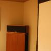
psg Posted November 18, 2010 Author Share Posted November 18, 2010 This one is a bit out of focus... This is the first time, with all side panels on giving the full shape, that I realised how big this thing was. The pictures really do not give the sense of scale. Quote Link to comment Share on other sites More sharing options...
Billy joe Posted November 18, 2010 Share Posted November 18, 2010 When my wife saw my Tuba fully assembled. She said "is that thing really going in the house". She finally got used to it though. Quote Link to comment Share on other sites More sharing options...
CECAA850 Posted November 18, 2010 Share Posted November 18, 2010 Peter, that looks absolutely great. You can see a tremendous ammount of work in those pics. You're doing a great job. I'm getting excited for you! Carl Quote Link to comment Share on other sites More sharing options...
psg Posted November 19, 2010 Author Share Posted November 19, 2010 Thanks! Baltic birch looks great indeed. It's turning out nicely. I'll have some finish decisions to make soon. Quote Link to comment Share on other sites More sharing options...
CECAA850 Posted November 19, 2010 Share Posted November 19, 2010 What are the small dowell looking pieces going to the corner reflectors? Are they braces for the construction process or are they permanent? Quote Link to comment Share on other sites More sharing options...
psg Posted November 19, 2010 Author Share Posted November 19, 2010 Just braces while the PL dries. We get lots of thin plywood piece during this build since the rough cuts are typically 1/2" too big on one side. I measure the gap, cut them to sizeand squeeze them in as braces. Works well! Quote Link to comment Share on other sites More sharing options...
Vicoaster Posted November 19, 2010 Share Posted November 19, 2010 Almost there Peter, even if it has been slow going the Tuba is almost finished... I wish I had some time to work on mine, so much on the go with the kitchen and starting a new job that I dare not even try... So, you mentioned finish, have you come up with anything? Quote Link to comment Share on other sites More sharing options...
psg Posted November 19, 2010 Author Share Posted November 19, 2010 So, you mentioned finish, have you come up with anything? My initial idea was to remove all screws, put in pegs, router edges, sand, stain to match WO Klipschorns. I know the pegs will have a different color, so someone suggested that I just use a latex-based filler, something like this: http://www.lepageproducts.com/ProductDetail.aspx?pid=112 Come in walnut colour, which could be a good starting colour with the stain. Quote Link to comment Share on other sites More sharing options...
ClaudeJ1 Posted November 19, 2010 Share Posted November 19, 2010 Carl, The one photographed has a clear acrylic panel right over the woofer by the mouth, but you can do whatever you like there. If you don't put an access panel there you can still get to the woofer though the mouth, but it will be tight. I have not built it yet, so I will decide at that time whether to cut an access panel or not. It's the lowest air pressure point of the horn, so no worries there. Quote Link to comment Share on other sites More sharing options...
Vicoaster Posted November 19, 2010 Share Posted November 19, 2010 Carl, The one photographed has a clear acrylic panel right over the woofer by the mouth, but you can do whatever you like there. If you don't put an access panel there you can still get to the woofer though the mouth, but it will be tight. I have not built it yet, so I will decide at that time whether to cut an access panel or not. It's the lowest air pressure point of the horn, so no worries there. Picture, I don't see it? Quote Link to comment Share on other sites More sharing options...
CECAA850 Posted November 19, 2010 Share Posted November 19, 2010 Carl, The one photographed has a clear acrylic panel right over the woofer by the mouth, but you can do whatever you like there. If you don't put an access panel there you can still get to the woofer though the mouth, but it will be tight. I have not built it yet, so I will decide at that time whether to cut an access panel or not. It's the lowest air pressure point of the horn, so no worries there. Picture, I don't see it? Thanks again Claude. I didn't see a pic either, just the plan drawing. It's too bad the box wasn't drawn where the front panel could be flush mounted to the sides with speaker gasket material. That way you could just unscrew the front panel and it'd be right there. Quote Link to comment Share on other sites More sharing options...
psg Posted November 19, 2010 Author Share Posted November 19, 2010 DP Quote Link to comment Share on other sites More sharing options...

Recommended Posts
Join the conversation
You can post now and register later. If you have an account, sign in now to post with your account.
Note: Your post will require moderator approval before it will be visible.