erik2A3 Posted June 7, 2017 Share Posted June 7, 2017 Looking at the pictures you posted, have a closer look at the main filter capacitors and filament connections on the 2a3. I know you know what I'm about to mention, Bruce, and I say this as a matter of habit: MAKE SURE RESERVOIR CAPS ARE NOT HOLDING HIGH VOLTAGE BEFORE DOING ANY WORK. The Moondog does not use a bleeder on the output of the power supply, so this becomes doubly important. Quote Link to comment Share on other sites More sharing options...
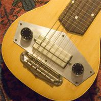
John Warren Posted June 7, 2017 Share Posted June 7, 2017 Is area highlighted indicative of something? Quote Link to comment Share on other sites More sharing options...
Marvel Posted June 8, 2017 Author Share Posted June 8, 2017 I'll get it back open and have a closer look, John. It may be a combination of the lighting and something from the original construction. The thick brass top plates have some massive discoloration on the underside. I'll get some other pics along the way as I check things out. It's been a busy week at work and I haven't felt like digging into it in the evenings. (I say that realizing it is only Wednesday...) 1 Quote Link to comment Share on other sites More sharing options...
alzinski Posted June 8, 2017 Share Posted June 8, 2017 Why is there a resistor in the 5v winding serial to the rectifier heater? What value is it? Is it .40 ohms? That's going to drop your GZ37 heater voltage by over 1 volt. It's probably supposed to be R14 on the 6.3v winding? Quote Link to comment Share on other sites More sharing options...
erik2A3 Posted June 8, 2017 Share Posted June 8, 2017 alzinski, Where do you see a series resistor in the rectifier filament supply? Quote Link to comment Share on other sites More sharing options...
erik2A3 Posted June 8, 2017 Share Posted June 8, 2017 I would want to measure all voltages against the schematic, as well as test, in particular, the rectifier. The GZ37 is a nice looking tube, but I have purchased (apparently) NOS that measured very disappointingly for the price paid. I mentioned the value of input Solen cap for a reason -- it's not an aspect of power supply design that should just be taken as a 'whatever.....no big deal' sort of thing. 10uf is more than twice that listed in tube data for that valve, and, as such, is not insignificant. You might also want to check the state or quality of the epoxy that was originally used to attach the nylon stand-offs beneath the terminal strips. Mine, as well as those of a couple of other Moondog owners I have known, was either old or incorrectly mixed -- turning into something akin to chewing gum. A definite, greatly time-consuming pain to remove and renew with fresh, carefully mixed epoxy. Ron abandoned this approach with the DRDs he developed with Electra-Print (who designed the DRD circuit), using actual hardware for the standoffs instead the decidedly more messy and less permanent glue. There are a couple of other Moondog owners among us here, so hopefully some will benefit from at least a bit of this info. It's a good, fairly traditional single-ended design, and definitely worthy of the maintenance and technical checkup as mentioned above. Someone wrote me a couple of weeks ago wanting to buy my pair. Never. Quote Link to comment Share on other sites More sharing options...
Marvel Posted June 8, 2017 Author Share Posted June 8, 2017 The two Solens on the right end of the pic, are both 10mfd, and wired in parallel. One is the 630v, the other a 400v. The discoloration of the brass top plate that John circled is extremely old and mostly from the way the light was hitting it. It will take some time for me to go over this and take measurements. There are places where leads appear to have been heated enough to melt the vinyl insulation a LOT next to the solder joints. It's not very easy to get an iron around in that chassis. Quote Link to comment Share on other sites More sharing options...
alzinski Posted June 8, 2017 Share Posted June 8, 2017 3 hours ago, erik2A3 said: alzinski, Where do you see a series resistor in the rectifier filament supply? Why would they use two dual triode tubes and then only use one triode from each bottle? Strange.......... Quote Link to comment Share on other sites More sharing options...
erik2A3 Posted June 8, 2017 Share Posted June 8, 2017 If those two Solens are wired in parallel, they are wired incorrectly. That would give you a net capacitance of 20uf (even worse for the GZ 37), AND the voltage rating for the paralleled caps (which essentially form one capacitor) would only be that of the 400V capacitor. Quote Link to comment Share on other sites More sharing options...
erik2A3 Posted June 8, 2017 Share Posted June 8, 2017 Ah, I see. That may have been installed in series to lower the filament voltage (as you mentioned) if, by nature of the variability of mains voltages, to achieve the necessary 5 volts. And you are definitely correct about the use of two dual triodes! That's perceptive, and you're correct too, about the use of two 6sn7s not being necessary. The amp will work exactly the same if one were to use both sections of just one. There is a reason, however, though not a technical one: The Moondog was built on the same platform of another amp by the same designer called the Laurel 300B. It was also a single-ended amp which was in fact designed to use an additional necessary tube. In other words, the two amps use the same chassis plate, but the Moondog made use of what would have been an empty chassis punch by installing the extra octal driver, but only using one side of both tubes. Quote Link to comment Share on other sites More sharing options...
Marvel Posted June 8, 2017 Author Share Posted June 8, 2017 Soooo... Erik, if I remember correctly, you had these in your possession at one time. Did these have this in them when you had them? The thing is, whoever did this, I have used them this way for years now. Bruce Quote Link to comment Share on other sites More sharing options...
erik2A3 Posted June 9, 2017 Share Posted June 9, 2017 Well Bruce, Seems there are a few too many letter o's in your opening statement there. That was a long, long time ago. I also know who built them to begin with, and know he wouldn't have made a mistake like that. You indicated you thought you were the 4th owner, correct? That means these poor fellows have had a surprising number of owners before you. Who knows what was done in the name of 'improvement'. How about a very close image of the actual connection? Is there a chance they aren't actually in parallel? The way Ron set them up was for those not accustomed to building to be able to refer to positions on the terminal boards, many of which I by-passed for shorter signal paths on my own amps. It can be difficult, sometimes, to tell exactly what is going where. If you have been using them for years without problems -- then good. I'm glad to hear it. Best luck in tracking the problem down. My effort in this was to try to help you. erik Quote Link to comment Share on other sites More sharing options...
Marvel Posted June 9, 2017 Author Share Posted June 9, 2017 nah, I meant no offence, Erik. I think those caps may be in series. I've also found two different schematics for these. I got the manual from the Welborne site as well, plus a pictorial. I'll get a better look on the weekend. i used to have the info on who built/owned these courtesy of you, but I can't find the file. I haven't changed these in any way and I don't believe the one before me did either. I'm sure my mind is getting foggy... I appreciate the help and only wish I could afford the grid chokes. Quote Link to comment Share on other sites More sharing options...
erik2A3 Posted June 9, 2017 Share Posted June 9, 2017 All good Bruce... Series connection is conceivable, and I may have seen that all those years ago -- where the time has gone, I just don't know. If it is an error in wiring, I would be the first to admit I've made more than my share in the past. In fact, making mistakes and learning from much trial and error has hopefully helped me avoid fewer of those as I also continue to learn. That cap might also have been used as a bypass elsewhere, perhaps. And agreed. Those little grid chokes are gems in both performance and price. I don't have any right now, either, having sold my only pair within the Horus 2a3 amps I built (or, more accurately, my own version of the design, which was most definitely and strongly derived from Lessard's outstanding original circuit). Without his work, the pair I built wouldn't have been possible. Quote Link to comment Share on other sites More sharing options...
alzinski Posted June 9, 2017 Share Posted June 9, 2017 To me it doesn't look like they are in series or in parallel. Follow the wires and do a continuity test to confirm but this is what I think is going on. C2 and C3 are supposed to be a multi section can cap but it's not in this amp. You can follow the wires to and from the choke. The white wire goes from C1 to the choke and the black wire returns from the choke to the board, that point on the board has a yellow wire going to C2 and R13 which goes over to C3. It then looks like a white wire above the board carries from C3 over to the orange wire of the output transformer. I don't want to sound harsh but this is a poor desing that uses expensive parts for no actual good reason. No need for poly caps in the power supply. This is a single ended amp and the output stage's signal goes through the power supply, specifically C3, it would be better to just use regular electrolytics throughout the power supply and just use a very large C value for C3 to keep the AC impedance low for all frequencies, 680uF works, it is 11 ohms at 20Hz where the 10uF 400v used in your amp is 800 ohms. There are two unused triodes that could have been put to good use, maybe a follower stage directly coupled to the 2A3. Maybe more open loop gain to use some global feedback. In the audio biz it appears people that don't understand good engineering practices tend to try and use expensive parts thinking it will be better, it's not, no substitute for sound engineering and proper use of components. Quote Link to comment Share on other sites More sharing options...
Marvel Posted June 9, 2017 Author Share Posted June 9, 2017 3 hours ago, alzinski said: I don't want to sound harsh but this is a poor desing that uses expensive parts for no actual good reason. That's your opinion. After having bought them (used, I'm the 4th owner), I have not been at all dissappointed at all. It matters not to me that they have expensive parts, but I wouldn't change to less expensive/different parts and tale a chance on them sounding less. The best part about them is the output transformers. Mine are Magnequest, although they used others as well. Different parts and design in a power supply can have a huge diifference on the sound and character of an amp. You can build yours any way you wantto build it. Ron Welborne's designs are good, even if he wasn't a good businessman. Quote Link to comment Share on other sites More sharing options...
mike stehr Posted June 10, 2017 Share Posted June 10, 2017 Like Joe Roberts says; "It's hard to build a bad 2A3 amplifier." Quote Link to comment Share on other sites More sharing options...
alzinski Posted June 10, 2017 Share Posted June 10, 2017 1 hour ago, Marvel said: That's your opinion. After having bought them (used, I'm the 4th owner), I have not been at all dissappointed at all. It matters not to me that they have expensive parts, but I wouldn't change to less expensive/different parts and tale a chance on them sounding less. The best part about them is the output transformers. Mine are Magnequest, although they used others as well. Different parts and design in a power supply can have a huge diifference on the sound and character of an amp. You can build yours any way you wantto build it. Ron Welborne's designs are good, even if he wasn't a good businessman. I agree 100% about the output transformers, they are the most important part in the amp and is an area where you don't want to skimp. I am not in the amplifier business but knowing a thing or two about electronics and having heard hundreds of amps in my time I have an idea of what to do and what not to do, what works well and what doesn't work so well. I only offer advice from my life experiences, whether people listen or not is another thing. I am just trying to help you get your amp up and running. The 2A3 is a wonderful tube and it is indeed hard to make it sound bad. Quote Link to comment Share on other sites More sharing options...
Marvel Posted June 10, 2017 Author Share Posted June 10, 2017 It is certanly true that there really only needs to be a single 6SN7 on each amp, but it is what it is. If I were building a pair new, I might go with a single one to see how it would work out. I really do appreciate the input, no pun intended. Looking at the underside of these, they aren't very tidy, but they've been great amps. I really doubt I will ever part with them. The only others I would really like to try would be some George Wright or Quicksilver Audio models. Bruce Quote Link to comment Share on other sites More sharing options...
erik2A3 Posted June 10, 2017 Share Posted June 10, 2017 Alzinski, Your thoughts on this are appreciated and....yet... definitely your own. I am able to respond virtually sentence by sentence to your last response, but am simply too tired, etc., to bother. The Moondogs are beloved by those who own them, and to me that speaks for itself. They also have been very well received by experienced reviewers. I have many years with this particular design, as well as many other single-ended approaches - direct coupling, interstage coupling, parallel-feed, and so on. As Bruce stated, your responses represent your personal opinion, which, like my own, makes neither of us universally correct. Regarding boutique parts, meaning passive components such as resistor and capacitor types and brands, is very much a choice of personal 'seasoning to taste,' as it were. And the Moondogs are, in my opinion, well-worthy of such modification if the end result is to a particular owner's/user's liking. I joined this forum in 2002, and we spent much too much time trying to prove who was right and who was wrong -- or what or was not a 'worthy' design. Right, so the designer used two octal slots when he could have gotten by with one. The audio biz is also full of companies adapting suitable parts from one design to another. The only difference in this case is what amounts to slightly longer lead length between sections, as well as an extra filament; which is well within the operating parameters of the power supply. Jensen interstage coupling capacitors are a little more expensive than others, but one can fork out much more $$$ than what these reasonably-prioced PIO caps cost. You were kind to not sound harsh, and you don't.....really. But I have never really supported criticism of what someone else likes, audio or anything else. I submit we can offer suggestions for getting this amp up and running again without our potentially sharp and/or overt expressions regarding the efficacy of its design or abilities of its designer. Quote Link to comment Share on other sites More sharing options...

Recommended Posts
Join the conversation
You can post now and register later. If you have an account, sign in now to post with your account.
Note: Your post will require moderator approval before it will be visible.