mopardave Posted February 26, 2018 Share Posted February 26, 2018 Can anyone that knows explain how to measure plate current and cathode current and how to calculate to find proper bias settings for my EL34 amp using 4 output tubes. Think i have been doing this wrong taking readings off cathode with 10ohm resister and just reading meter and setting bias. Thanks Quote Link to comment Share on other sites More sharing options...
tube fanatic Posted February 27, 2018 Share Posted February 27, 2018 With pentodes cathode current is a combination of plate current and screen current. As to proper bias for your amp, the best thing is to set up the tubes per the manufacturer's instructions. What amp are you talking about, and can you post its schematic? Maynard 1 Quote Link to comment Share on other sites More sharing options...
mopardave Posted February 27, 2018 Author Share Posted February 27, 2018 1 hour ago, tube fanatic said: With pentodes cathode current is a combination of plate current and screen current. As to proper bias for your amp, the best thing is to set up the tubes per the manufacturer's instructions. What amp are you talking about, and can you post its schematic? Maynard Audcom 900. Chinese amp EL34 rated at 30w/ch. Not sure i have a schematic. I will post if i do. I have measured a few things and can say it has 480-485v plate and a 10.2ohm resister on the cathode.. Quote Link to comment Share on other sites More sharing options...
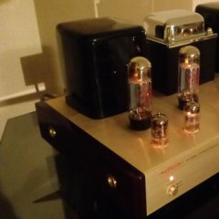
mopardave Posted February 28, 2018 Author Share Posted February 28, 2018 Ok, here ya go. Quote Link to comment Share on other sites More sharing options...
tube fanatic Posted March 6, 2018 Share Posted March 6, 2018 I had a moment to glance at the schematic and see that the 10 ohm resistor you are referring to is in series with the plate (pin 3), not the cathode which is grounded. If you measure the voltage across that 10 ohm resistor you can use Ohm's Law to calculate the plate current and plate dissipation based on the plate voltage you measured. You can also measure across the 200 ohm resistor in series with the screen (pin 4) to calculate screen dissipation which is also very important. Screen voltage can be measured from pin 4 to ground. And, you can measure the bias voltage from pin 5 to ground. With all of that information you can get an idea about operating conditions. I can try to look at this in more detail if you run into problems. Maynard Quote Link to comment Share on other sites More sharing options...
mopardave Posted March 7, 2018 Author Share Posted March 7, 2018 3 hours ago, tube fanatic said: I had a moment to glance at the schematic and see that the 10 ohm resistor you are referring to is in series with the plate (pin 3), not the cathode which is grounded. If you measure the voltage across that 10 ohm resistor you can use Ohm's Law to calculate the plate current and plate dissipation based on the plate voltage you measured. You can also measure across the 200 ohm resistor in series with the screen (pin 4) to calculate screen dissipation which is also very important. Screen voltage can be measured from pin 4 to ground. And, you can measure the bias voltage from pin 5 to ground. With all of that information you can get an idea about operating conditions. I can try to look at this in more detail if you run into problems. Maynard Ok, thanks. When i get a minute ill remeasure those points. Quote Link to comment Share on other sites More sharing options...
mopardave Posted March 7, 2018 Author Share Posted March 7, 2018 18 hours ago, tube fanatic said: I had a moment to glance at the schematic and see that the 10 ohm resistor you are referring to is in series with the plate (pin 3), not the cathode which is grounded. If you measure the voltage across that 10 ohm resistor you can use Ohm's Law to calculate the plate current and plate dissipation based on the plate voltage you measured. You can also measure across the 200 ohm resistor in series with the screen (pin 4) to calculate screen dissipation which is also very important. Screen voltage can be measured from pin 4 to ground. And, you can measure the bias voltage from pin 5 to ground. With all of that information you can get an idea about operating conditions. I can try to look at this in more detail if you run into problems. Maynard I believe that 10 ohm resister is on pin 8 not 3. I had some mods performed on this amp so there may be some differences compared to the schematic. Quote Link to comment Share on other sites More sharing options...
LTusler Posted April 10, 2018 Share Posted April 10, 2018 Not sure if this helps but I run a VTA ST-70, and the recommended bias voltage on pin 5 is .400 VDC, the tubes will last longer. But YMMV. Quote Link to comment Share on other sites More sharing options...

Recommended Posts
Join the conversation
You can post now and register later. If you have an account, sign in now to post with your account.
Note: Your post will require moderator approval before it will be visible.