ajsons Posted October 29, 2018 Author Share Posted October 29, 2018 . Quote Link to comment Share on other sites More sharing options...
Invidiosulus Posted October 29, 2018 Share Posted October 29, 2018 3 minutes ago, ajsons said: Sheet 7. Now this one needs to be checked to make sure the dimensions are right. Hopefully, before the end of this week I can check it, along with Sheet 11. I will repost this sheet after I check it. The 35.01 degree bevel on the end of the throat side piece is only correct in the orthographic top down view. The actual bevel relative to the piece as you would cut it on a saw should be closer to 31.6 degrees. I believe the relative angles for the boards can be checked using a compound angle calculator such as this one. http://jansson.us/jcompound.html I entered the numbers with side A as the throat side, 90 degrees from the floor, and side B as the throat front, 66.02 degrees from the floor with 125.01 degrees between the pieces due to the 54.99 degree cut at the back of the throat sides. Using the angles from the calculator and figuring some right scalene triangle should make the dimensions somewhat straightforward to calculate if someone has the time. That being said, Linear Geometry in 3D vector space isn't exactly my thing. Cheers, Josh Quote Link to comment Share on other sites More sharing options...
ajsons Posted October 29, 2018 Author Share Posted October 29, 2018 . Quote Link to comment Share on other sites More sharing options...
ajsons Posted October 29, 2018 Author Share Posted October 29, 2018 . Quote Link to comment Share on other sites More sharing options...
ajsons Posted October 29, 2018 Author Share Posted October 29, 2018 . Quote Link to comment Share on other sites More sharing options...
ajsons Posted October 29, 2018 Author Share Posted October 29, 2018 . Quote Link to comment Share on other sites More sharing options...
ajsons Posted October 29, 2018 Author Share Posted October 29, 2018 . Quote Link to comment Share on other sites More sharing options...
carlthess40 Posted October 29, 2018 Share Posted October 29, 2018 Hello guys. This thread has me quite interested ,when all the sheets are compiled and gone through is there anyway possible that I could get a PDF copy or some type a copy of these I’m a highly accomplished Carpender and I would like to do this build as time permits been very successful at making quite a few Klipsch clones and also making four or five pretty amazing tuba subs I would really love to try this build ,with your permission of courseThank you Carl Quote Link to comment Share on other sites More sharing options...
ajsons Posted October 29, 2018 Author Share Posted October 29, 2018 . Quote Link to comment Share on other sites More sharing options...
ajsons Posted October 30, 2018 Author Share Posted October 30, 2018 On 10/29/2018 at 3:22 PM, Invidiosulus said: . Quote Link to comment Share on other sites More sharing options...
Invidiosulus Posted October 30, 2018 Share Posted October 30, 2018 Measuring the angle between the edges of the top of the board will give you a different angle than measuring the angle between the faces of the board. This is due to the miter angle. In the attached quick sketch you can see that the distance between the dashed red lines is greater at the top of the piece when measured in the horizontal plane. When measured relative to the two faces the distance is less. This accounts for the difference in measured angle as well. A table saw would need need to be set for the angle between the faces and not the edges or the cut would not come out right. So the measured angle in the top view is correct, it just wouldn’t be the most helpful to actually make the part in question. Quote Link to comment Share on other sites More sharing options...
planetred Posted October 30, 2018 Share Posted October 30, 2018 Welcome back ajsons! FYI I did some polarity checking on my Classics and realized the C15W (both green and silver frames) are out of phase. When wired 1&3 pos and 2&4 neg (Com, i.e. BLK), cone pushes forward. T-30 gold and silver painted drivers are correct, (T1 pos T2 neg). HF-206 gold driver was was correct. However, silver painted HF-206 driver was not. (for correction T2 pos T1 neg). I hope this is clear. Quote Link to comment Share on other sites More sharing options...
carlthess40 Posted October 30, 2018 Share Posted October 30, 2018 Yes, Carl, I can make you a pdf copy, although you can save this jpegs and print your own. And you don't need anybody's permission. Now, where is Lake Mary and how much will charge to build a set? ArmandoHiI’m near I:4 and Lake Mary blvdI’ve only look at the plans in bits so far and have no way to know of how much labor will be in to one yet Quote Link to comment Share on other sites More sharing options...
planetred Posted October 30, 2018 Share Posted October 30, 2018 I used these plans with Revision "A" correction. Hope this helps- Quote Link to comment Share on other sites More sharing options...
planetred Posted October 30, 2018 Share Posted October 30, 2018 I gotta get to bed. Quote Link to comment Share on other sites More sharing options...
ajsons Posted October 30, 2018 Author Share Posted October 30, 2018 . Quote Link to comment Share on other sites More sharing options...
carlthess40 Posted October 30, 2018 Share Posted October 30, 2018 ThanksI’ll print it out tomorrow and try to make sense of it Quote Link to comment Share on other sites More sharing options...
planetred Posted October 30, 2018 Share Posted October 30, 2018 Very happy to help. Quote Link to comment Share on other sites More sharing options...
ajsons Posted October 30, 2018 Author Share Posted October 30, 2018 . Quote Link to comment Share on other sites More sharing options...
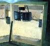
Invidiosulus Posted October 30, 2018 Share Posted October 30, 2018 This was done in a hurry as I’m getting ready to head for work so I didn’t worry too much about the exact tenths of a degree. I set the bevel angle to 31.6 ish degrees. Next I made a 28.5 degree mark on my crosscut sled. Aligning the piece of wood to the miter angle gave me a cut that sits perfectly on the 35 degree angle needed to match the front piece. I took a square and made a mark at a right angle to the cut edge. Quote Link to comment Share on other sites More sharing options...

Recommended Posts
Join the conversation
You can post now and register later. If you have an account, sign in now to post with your account.
Note: Your post will require moderator approval before it will be visible.