mopardave Posted January 27, 2019 Share Posted January 27, 2019 Can someone explain again how to figure plate voltage drop? I'm measuring plate voltage on my Douk kt88 amp at 350v, measuring between 8 and 3 pin. Just trying to confirm the dc/ma gauges are measuring bias accurately. Thanks Quote Link to comment Share on other sites More sharing options...
mikebse2a3 Posted January 28, 2019 Share Posted January 28, 2019 Do you have a schematic of the amplifier..? Quote Link to comment Share on other sites More sharing options...
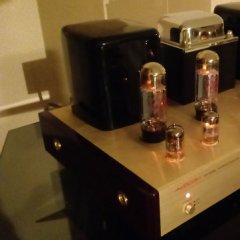
mopardave Posted January 28, 2019 Author Share Posted January 28, 2019 1 hour ago, mikebse2a3 said: Do you have a schematic of the amplifier..? No and there is no way I can get one from china. The manual was in Chinese, so I asked for one in English and they sent a pic of the amp with the properly labeled tubes. Quote Link to comment Share on other sites More sharing options...
NOSValves Posted January 29, 2019 Share Posted January 29, 2019 get what you pay for I guess ... Are the meters up front for bias? If so why do you not trust them? Quote Link to comment Share on other sites More sharing options...
mopardave Posted January 29, 2019 Author Share Posted January 29, 2019 22 minutes ago, NOSValves said: get what you pay for I guess ... Are the meters up front for bias? If so why do you not trust them? I really like the amp. Sounds better than I expected. Thought I would see if I could trust those meters, so I pulled the cover and with a multimeter I found a spot to test from on each side of the resistor on pin 8. Multimeter read .666 on left tube and .669 on right while the dc/ma meters on front read .600 on left and .650 on right. The left meter is off a bit if I measured correctly. Quote Link to comment Share on other sites More sharing options...
NOSValves Posted January 29, 2019 Share Posted January 29, 2019 change your meter to read resistance and see what the value of those resistors are... also what does the meter say its displaying current or voltage? Quote Link to comment Share on other sites More sharing options...
mopardave Posted January 29, 2019 Author Share Posted January 29, 2019 29 minutes ago, NOSValves said: change your meter to read resistance and see what the value of those resistors are... also what does the meter say its displaying current or voltage? Had the meter on ohm scale and resistor reads 1.2 once it settles. For bias had it on ma scale and it read .666 and .669 . Current would be ma scale correct? I will redo these measures this weekend. For plate voltage I use ac or DC scale? Quote Link to comment Share on other sites More sharing options...
mopardave Posted January 30, 2019 Author Share Posted January 30, 2019 On 1/28/2019 at 7:50 AM, mopardave said: No and there is no way I can get one from china. The manual was in Chinese, so I asked for one in English and they sent a pic of the amp with the properly labeled tubes. I was reading some info on Rob Robinette site about plate voltage drop, bias etc, I'm not quite understanding where you find the" center tap" and what scale you would use negative voltage or positive voltage? A bunch of interesting info on his site. Quote Link to comment Share on other sites More sharing options...
tube fanatic Posted January 30, 2019 Share Posted January 30, 2019 13 hours ago, mopardave said: Had the meter on ohm scale and resistor reads 1.2 once it settles. For bias had it on ma scale and it read .666 and .669 . Current would be ma scale correct? I will redo these measures this weekend. For plate voltage I use ac or DC scale? You can't measure current across a component. To do so with your meter it would have to be in series with the component. You need to measure the DC voltage drop (using the lowest scale on your meter) across the 1.2 ohm resistor. Divide what you measure by 1.2 to get the current. Be extremely careful when measuring high voltages in the plate or screen circuit (DC scale). Those voltages can kill you!!! Be sure to keep your left hand in your pocket and work one-handed. Wear sneakers or other footwear with a rubber sole, remove any rings from your fingers, work on an insulated surface (not metal), and take your time. Why are you so concerned about the operating point of the tubes? To figure out what the designers did you would need to not only measure voltages, but also the impedance of the output transformers so the distortion figures could either be graphed or run through a simulator program. Maynard Quote Link to comment Share on other sites More sharing options...
mopardave Posted January 30, 2019 Author Share Posted January 30, 2019 Absolutely. Don't want to die finding these figures, but I want to be confident the on board meters are correct when setting bias. Its just nice to have all the specs on your amp. Quote Link to comment Share on other sites More sharing options...
NOSValves Posted January 31, 2019 Share Posted January 31, 2019 Maynard is right you can't get an accurate measurement using the current setting on the digital multimeter. The meter would have to have zero ohms of internal resistance to shunt out the 1.2 ohm resistor which no modern digital meter can do that I know of. So when your reading the current there is still some current sneaking through the 1.2 ohm resistor making your measurement inaccurate. So you use the voltage drop and ohms law. Most likely those resistors are 1 ohm and the meter leads are adding a bit. So again what do those meters on the front say they are displaying on the front of the amp volts DC or current (mA) Quote Link to comment Share on other sites More sharing options...
mopardave Posted January 31, 2019 Author Share Posted January 31, 2019 57 minutes ago, NOSValves said: Maynard is right you can't get an accurate measurement using the current setting on the digital multimeter. The meter would have to have zero ohms of internal resistance to shunt out the 1.2 ohm resistor which no modern digital meter can do that I know of. So when your reading the current there is still some current sneaking through the 1.2 ohm resistor making your measurement inaccurate. So you use the voltage drop and ohms law. Most likely those resistors are 1 ohm and the meter leads are adding a bit. So again what do those meters on the front say they are displaying on the front of the amp volts DC or current (mA) I tried following some direction from Rob Robinette site and a couple things I couldn't figure out was where the center tap was to measure resistance and how to totally drain the capacitors. I did plug some figures I found into his calc and it suggested max bias( 70%) to be set at .70ma with 350 plate voltage and .094v on the cathode resistor. I don't really know what i'm doing, so I just measured bias off the cathode resistor and set it to .70ma on my multimeter. The left on board meter reads .60ma and the right reads .65ma. Not accurate to my multimeter nor to each other. I am going to order a fluke or a klein autoranging meter and remeasure, then leave it be. I keep poking around in there i'll end up dead. Quote Link to comment Share on other sites More sharing options...
tube fanatic Posted February 1, 2019 Share Posted February 1, 2019 You are too concerned over something which isn't all that critical in the context of things. A few milliamps one way or the other isn't going to be audible since normal variations in production tolerances of the tubes and output transformers can be more of an issue. Remember, with 350V on the plate, you would have to run the tubes at 120 milliamps to reach the 42 watt plate dissipation rating. So, don't worry about it and just enjoy the amp. The front panel meters are close enough to be used and relied on. And, please go on Youtube and watch some videos on high voltage safety before you mess around under the chassis again! Maynard Quote Link to comment Share on other sites More sharing options...
mopardave Posted February 1, 2019 Author Share Posted February 1, 2019 13 minutes ago, tube fanatic said: You are too concerned over something which isn't all that critical in the context of things. A few milliamps one way or the other isn't going to be audible since normal variations in production tolerances of the tubes and output transformers can be more of an issue. Remember, with 350V on the plate, you would have to run the tubes at 120 milliamps to reach the 42 watt plate dissipation rating. So, don't worry about it and just enjoy the amp. The front panel meters are close enough to be used and relied on. And, please go on Youtube and watch some videos on high voltage safety before you mess around under the chassis again! Maynard Good to hear that. It just bothers me that if I bias using the front bias meters, left tube with be burning hotter than the right tube. Also I don't mind buying new tubes every year, so I like to bias on max recommendations usually 70%. Thanks Quote Link to comment Share on other sites More sharing options...
tube fanatic Posted February 1, 2019 Share Posted February 1, 2019 Well, even running at 70%, a couple of watts difference between the tubes is not going to affect longevity. If that is a major concern you need to address the filament voltage and, if it exceeds 6.3, it should be addressed. Also, you may want to consider inrush protection, as the greatest stress on the filaments occurs at initial turn-on. Lastly, consider getting a whisper fan which can blow across the output tubes. Maynard Quote Link to comment Share on other sites More sharing options...
mopardave Posted February 1, 2019 Author Share Posted February 1, 2019 4 hours ago, tube fanatic said: Well, even running at 70%, a couple of watts difference between the tubes is not going to affect longevity. If that is a major concern you need to address the filament voltage and, if it exceeds 6.3, it should be addressed. Also, you may want to consider inrush protection, as the greatest stress on the filaments occurs at initial turn-on. Lastly, consider getting a whisper fan which can blow across the output tubes. Maynard Yes, and there is no fuse in this amp I can find. Quote Link to comment Share on other sites More sharing options...
tube fanatic Posted February 1, 2019 Share Posted February 1, 2019 Check the IEC socket. The fuse may have been incorporated in that. If not, adding one is very easy. Maynard Quote Link to comment Share on other sites More sharing options...
mopardave Posted February 1, 2019 Author Share Posted February 1, 2019 5 minutes ago, tube fanatic said: Check the IEC socket. The fuse may have been incorporated in that. If not, adding one is very easy. Maynard Ok, i'll check that. Quote Link to comment Share on other sites More sharing options...
mopardave Posted February 1, 2019 Author Share Posted February 1, 2019 7 minutes ago, tube fanatic said: Check the IEC socket. The fuse may have been incorporated in that. If not, adding one is very easy. Maynard You are correct. My dumb *** should have known to check there as the Audcom amp fuse is located in the same place. Thanks Quote Link to comment Share on other sites More sharing options...
NOSValves Posted February 5, 2019 Share Posted February 5, 2019 Dave, Do you have a decent digital camera? If so take a close up shot of one of those meters. I wouldn't be surprised your measurement is more off than the meters. I again agree with Maynard (I think the red sea just parted) this is much to do about nothing . Quote Link to comment Share on other sites More sharing options...

Recommended Posts
Join the conversation
You can post now and register later. If you have an account, sign in now to post with your account.
Note: Your post will require moderator approval before it will be visible.