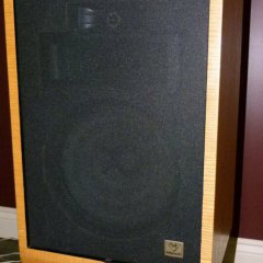
efzauner Posted February 23, 2020 Share Posted February 23, 2020 Hello fans! Over 2 years ago I purchased a non functional SWR15 for $200 Canadian. The owner had attempted a woefully inadequate repair. An attempt was made to replace the main SMPS inductor L302 but no other electronic parts where replaced. Plus the cabinet was not in great shape as it seemed to have undergone some water damage or at least it was in a very damp basement for a while. Fixing the cabinet, re gluing etc was the easy part. I did not try to make it cosmetically pristine. Just working. It is in the corner of the HT room behind the sectional sofa so nobody sees it anyway. I removed the amp and face place electronics board and replaced it with a wood panel so I could connect speaker terminals and use it with an external amp... I began a repair 2 years ago but stopped. Finally got it done. I consider this a more advanced repair and I am not going to go into every details on repair basics. If you don't know how to check PS voltages, check for blown transistors, desolder and solder and mount transistors with ceramic insulator and heatsink compound I suggest you read up on that stuff. The amp is powered by +/- 85v and is in a bridge configuration that is floating. Not easy to connect a grounded scope probe to look at signals. I did not have a differential probe. In the end the repair was winding a new inductor and replacing almost all of the power semiconductors in the PS and PA board. Had it been some other circuitry this may have been more difficult to troubleshoot. Service manual was easily available from HiFi Engine but it was lacking info on the main switch mode power supply 150uH inductor L302 and had no bias adjustment info. Long searches led me to the JBL HTPS 400 and infinity-Intermezzo 1.2 and4-1t manuals. that had the identical Indigo electronics. Note that Indigo makes the entire kit including the feature board with all the LPF and protection circuits. The Infinity manual has some good blown fuse troubleshooting info also. These 2 manuals gave me the inductor value and bias adjustment. Note that its almost as if they keep things out on purpose. The Klipsch manual had no inductor value nor bias info and the JBL manuals lacked the envelope following SMPS schematic! The Infinity manual had both. The only differences are how the main PS board and SMPS Bash amp board are mechanically mounted. In the Klipsch it is 1 assembly on heat sink, on the others they are separate. After disassembly and putting it all on my test bench for testing. I had removed the control panel also so that I could use the power cord and on off switch as well as signal source as necessary. There are a number of circuits for thermal shutdown (with a thermistor on one of the PA mp Mosfets. This was originally thermal epoxied on to the TO222 transistor but I did not want to spend $50 for thermal epoxy so I glued the leads to the side of the case and used normal thermal paste between the thermistor body and transistor heat sink tab. ). Over current sensing. Clipping detection, Soft clipping, Auto on etc. so since I had no clue where everything was I decided to have the entire setup. I did not try to just power the PS and Bash board. It may work. So the main guts are on 2 boards mounted on a common heatsink that screws to the brace between the sub and passive radiator : A general Switch Mode power supply board that provides all DC levels to the various circuits as well as the main 170V to the Bash amp board. The Bash board has the envelope following buck mode switching power supply and the main amp in a bridge-H config similar to car audio amps. a single IRF640 N fet on each side and paralleled IRF9640 P channels on the other legs of the bridge. The envelope following Buck PS has 2 IRF640s and a power diode. First thing I noticed was what looked like a home made inductor.. Heads up! Plugged it all in and found that the bash amp was shorted. Removed that inductor and the short was removed and the mains where back up at 170V. First conclusion was that something after that inductor was shorted. Easy enough to test the power diode and all the power mosfets. That was all that required replacing. I wound my own inductor based on the 150uH from the JBL manual and double tested the value with my old HP impedance analyzer and in a resonant circuit with a known capacitor. And that was it! up and running again! see pics attached... the Klipsch manual is on Hifi Engine. I do not recall where I found the JBL and Infinity manuals. They are over 2Mb and don't fit here but send me a message with your email and I will be happy to email them. Quote Link to comment Share on other sites More sharing options...
efzauner Posted February 23, 2020 Author Share Posted February 23, 2020 more pics of passive radiator removed to access amp. as well as repaired amp ready to install with new inductor. Quote Link to comment Share on other sites More sharing options...
efzauner Posted February 23, 2020 Author Share Posted February 23, 2020 Bash amp assembly with previous home made inductor that I replaced. Quote Link to comment Share on other sites More sharing options...
efzauner Posted February 23, 2020 Author Share Posted February 23, 2020 repaired bash amp 1 1 Quote Link to comment Share on other sites More sharing options...
efzauner Posted February 23, 2020 Author Share Posted February 23, 2020 6 hours ago, efzauner said: blown parts Power diode on left. Fet on right with thermistor Quote Link to comment Share on other sites More sharing options...
babadono Posted February 23, 2020 Share Posted February 23, 2020 What do you suppose was wrong with the original inductor? Also do you have the Infinity Documentation? @efzauner Quote Link to comment Share on other sites More sharing options...
efzauner Posted February 24, 2020 Author Share Posted February 24, 2020 3 hours ago, babadono said: What do you suppose was wrong with the original inductor? Also do you have the Infinity Documentation? @efzauner I suspect that it may have shown signs of overheating because of the short or just abuse. Maybe the owner thought that it was the only part that needed changing. Dunno. Quote Link to comment Share on other sites More sharing options...
CECAA850 Posted June 18, 2020 Share Posted June 18, 2020 @efzauner , would you have the service manual or schematic for the RSW-10? Quote Link to comment Share on other sites More sharing options...
WLDock Posted October 10, 2020 Share Posted October 10, 2020 Great Post, thanks for sharing! PM sent. Quote Link to comment Share on other sites More sharing options...
efzauner Posted November 30, 2020 Author Share Posted November 30, 2020 On 6/18/2020 at 4:03 PM, CECAA850 said: @efzauner , would you have the service manual or schematic for the RSW-10? sorry no I dont.. dont know of similarities with RSW15 Ed Quote Link to comment Share on other sites More sharing options...
OO1 Posted December 1, 2020 Share Posted December 1, 2020 On 2/23/2020 at 12:58 PM, efzauner said: Hello fans! Over 2 years ago I purchased a non functional SWR15 for $200 Canadian. The owner had attempted a woefully inadequate repair. An attempt was made to replace the main SMPS inductor L302 but no other electronic parts where replace Do you work as a repair technician in Montreal , for amplifiers or is this just a hobby - Quote Link to comment Share on other sites More sharing options...
JefferyLHenry Posted July 18, 2021 Share Posted July 18, 2021 On 2/23/2020 at 10:47 AM, efzauner said: Good work on the repairs. I have a similar bash indigo in a Cambridge p1000 that won’t power up. How did you confirm the failed power mosfets? I can’t see the parts numbers in your photo. Mine isn’t shorted and it DBT’s fine. I have tried to test the parts in circuit and pulled two - 1 9640 and one 640 and they are buggers to remove. I get very inconsistent results and so maybe they are just bad but not shorted? I also pulled the bridge rectifier and the main diode. Do some of these have complimentary transistors? We’re any other parts bad beyond the hacked inductors? My board looked clean and with zero obvious damage and the fuse was not blown. I have read the mosfets typically fail short? Was the tip 29, 30 or 47 okay? I also read to replace the 22uf electrolytic’s? The 2.2uf 450v cap next to the bridge rectifier was OL for esr so I also replaced it. We’re did you source the 9640’s I am having trouble finding them through mouser or digikey. Quote Link to comment Share on other sites More sharing options...

Recommended Posts
Join the conversation
You can post now and register later. If you have an account, sign in now to post with your account.
Note: Your post will require moderator approval before it will be visible.