Flevoman Posted March 13, 2022 Author Share Posted March 13, 2022 Ok, I've removed all drivers and filters.i will also upload pictures of everything. The previous owner had everything soldered in, so the man who is going to modify everything has to solder new connectors. I would like to hear your opinion about the wiring and perhaps other things you can see from the pictures. . Now that everything goes to that man, drivers and filters, to measure everything and for a recap, this is the best opportunity to tackle the wiring (if it is better) . If you see things in the pictures which I can imorove, I'd love to hear about it . Monday at the end of the day I take everything away to that guy. 1 Quote Link to comment Share on other sites More sharing options...
Flevoman Posted March 13, 2022 Author Share Posted March 13, 2022 Quote Link to comment Share on other sites More sharing options...
Flevoman Posted March 13, 2022 Author Share Posted March 13, 2022 Quote Link to comment Share on other sites More sharing options...
Flevoman Posted March 13, 2022 Author Share Posted March 13, 2022 Quote Link to comment Share on other sites More sharing options...
Flevoman Posted March 13, 2022 Author Share Posted March 13, 2022 Quote Link to comment Share on other sites More sharing options...
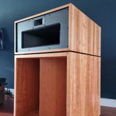
Flevoman Posted March 13, 2022 Author Share Posted March 13, 2022 The Tweeter Quote Link to comment Share on other sites More sharing options...
Flevoman Posted March 13, 2022 Author Share Posted March 13, 2022 Midhorn Quote Link to comment Share on other sites More sharing options...
billybob Posted March 13, 2022 Share Posted March 13, 2022 Yes those are the original capacitors from the factory. Nice photos. Quote Link to comment Share on other sites More sharing options...
Flevoman Posted March 13, 2022 Author Share Posted March 13, 2022 Wow.. 4 wires braided together for each positive and negative wire. That seems to me to be very exaggerated Quote Link to comment Share on other sites More sharing options...
Flevoman Posted March 13, 2022 Author Share Posted March 13, 2022 18 minutes ago, billybob said: Yes those are the original capacitors from the factory. Nice photos. Great, Then the chance is only greater that I will hear a difference 👍🏻 1 Quote Link to comment Share on other sites More sharing options...
billybob Posted March 13, 2022 Share Posted March 13, 2022 1 minute ago, Flevoman said: Great, Then the chance is only greater that I will hear a difference 👍🏻 Yes you should of course. Quote Link to comment Share on other sites More sharing options...
OO1 Posted March 13, 2022 Share Posted March 13, 2022 11 minutes ago, Flevoman said: Wow.. 4 wires braided together for each positive and negative wire. That seems to me to be very exaggerated I would replace the wire Quote Link to comment Share on other sites More sharing options...
Flevoman Posted March 13, 2022 Author Share Posted March 13, 2022 6 minutes ago, RandyH said: I would replace the wire And should I just use 1 blue and 1 black of the four wires instead of 4x4? Or do you say, remove everything and replace it with something completely different. Quote Link to comment Share on other sites More sharing options...
OO1 Posted March 13, 2022 Share Posted March 13, 2022 33 minutes ago, Flevoman said: And should I just use 1 blue and 1 black of the four wires instead of 4x4? Or do you say, remove everything and replace it with something completely different. you only need 12 wires ....3 blue -3 black for each crossover 1 blue , 1 black per driver x 3 drivers per speaker................you can remove the extra wires Quote Link to comment Share on other sites More sharing options...
pcbiz Posted March 13, 2022 Share Posted March 13, 2022 1 hour ago, Flevoman said: Wow.. 4 wires braided together for each positive and negative wire. That seems to me to be very exaggerated You may like the upgraded wiring as it is. Try listening to one wiring type at a time to see which one you prefer; your current blue/black wiring setup vs something else. I've done this three times on three different Klipsch speaker pairs, and have always preferred the upgraded wiring. The previous owner apparently preferred them as well. 1 Quote Link to comment Share on other sites More sharing options...
Deang Posted March 13, 2022 Share Posted March 13, 2022 Leave the wire alone, here’s why. Those PCB’s are not designed to be soldered on multiple times. The amount of heat applied to remove and replace the original wiring has possibly damaged the board - the foil layer will begin to separate from the board it’s glued to. Leave well enough alone. 1 Quote Link to comment Share on other sites More sharing options...
captainbeefheart Posted March 13, 2022 Share Posted March 13, 2022 I have never owned Chorus speakers but I was surprised to see wirewound resistors used instead of the ceramic ones I typically see klipsch use. Definitely have your guy put some fresh electrolytic capacitors in them. You most likely don't have to replace the yellow capacitors, a good tech should be able to test them to see how they perform and make a decision after that. Some people just like to replace them regardless which is also fine but make sure he gets the same mylar/polyester film types and not talk you into polypropylene. I know some people truly believe the electrolytic capacitors are in the signal path but they are not and you gain nothing stuffing ridiculously large film caps on the boards which will only give you a headache and possibly even rip pads up off the board. A new fresh set of electrolytic caps will last you at least another 30 years if your tech uses long life high temp types. You will find capacitors are highly debated, sadly 99% of the people commenting about them on the internet do not have a deep understanding of circuits and how capacitors work. This just means it's a very subjective debate based on highly biased listening experienced. The only other option for capacitors I would entertain for Klipsch speakers are the use of paper capacitors. As for the wiring, the 4 wires together for all the drivers is the silliest thing I have ever seen. Again people swear they hear differences changing the very small amount of wire in speaker, the only time I can see anything being audible is if something extreme was done and enough either inductance or capacitance was introduced parasitically but even that's a stretch. Silver, Copper, tinned, solid, stranded won't make one lick of sound difference, but some are easier to work with and will last longer in open air. 16awg stranded and tinned copper will be great, easy to work with and won't oxidize. 1 Quote Link to comment Share on other sites More sharing options...
captainbeefheart Posted March 13, 2022 Share Posted March 13, 2022 17 minutes ago, Crankysoldermeister said: Leave the wire alone, here’s why. Those PCB’s are not designed to be soldered on multiple times. The amount of heat applied to remove and replace the original wiring has possibly damaged the board - the foil layer will begin to separate from the board it’s glued to. Leave well enough alone. Yes it's mechanically ridiculous to have that much leverage on the traces by that amount of wire, there may already be slightly lifted traces from stress. If the boards are okay, I'd still carefully remove the wires from the board because it's only going to add more stress over time. You'll find out if the traces have been compromised which would be good to know, then repair the board as necessary and fit headers onto the board instead of soldering directly. Even if the pad is gone they aren't vias so just drill into a fresh section of trace and clean the insulation off, solder connector in and never put heat to it again. These types of boards are at least easily repaired. 2 Quote Link to comment Share on other sites More sharing options...
pcbiz Posted March 13, 2022 Share Posted March 13, 2022 I'm not angry. I'm just suggesting an A/B test by the owner. Quote Link to comment Share on other sites More sharing options...
Flevoman Posted March 13, 2022 Author Share Posted March 13, 2022 1 hour ago, RandyH said: you only need 12 wires ....3 blue -3 black for each crossover 1 blue , 1 black per driver x 3 drivers per speaker................you can remove the extra wires Sorry, I was not clear.. But this is exactly what I mean Quote Link to comment Share on other sites More sharing options...

Recommended Posts
Join the conversation
You can post now and register later. If you have an account, sign in now to post with your account.
Note: Your post will require moderator approval before it will be visible.