geoff. Posted July 2, 2022 Share Posted July 2, 2022 I tried some ALK Universal clones, but I still can’t get enough cowbell, lol. Is this the VTK-400 schematic, simplified? ...and thanks, as always, for the input Quote Link to comment Share on other sites More sharing options...
Deang Posted July 3, 2022 Share Posted July 3, 2022 3 hours ago, geoff. said: I tried some ALK Universal clones, but I still can’t get enough cowbell, lol. Are you sure they were built right? .30 should be .20mH. It’s basically a Super AA with a first order tweeter section. 2.5mH is the right value for the woofer. 1 Quote Link to comment Share on other sites More sharing options...
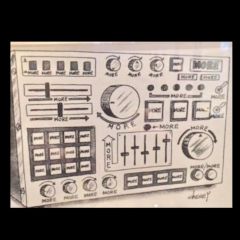
geoff. Posted July 3, 2022 Author Share Posted July 3, 2022 Thanks Dean, and yes, I think they (the ALK Universal clones) are built right. I did find the “suggested” -6db attenuation too uncharacteristically recessed for La Scalas, so mine are at -4db. In another thread recently I remarked at how impressed I was with the impact the (ALK Universals) had on the sound of the K-77. But even at that I prefer the treble turned to 11, lol, even as a teenager I would boost the treble. In the past month I have gone a week with each of the following crossovers, in this order; ALK, AA, and lastly A. All with refreshed capacitors. Even tried an idea from Bob Crites, an A set using a 6.8uF capacitor and tap 3, from a post decades ago before turning it back into an original A style. Listening to a pair of Klipsch type A’s right now and they are everything I like about La Scalas RIGHT up to about 80db. And that schematic above is the Super AA, after a little “white-out”. I’m guessing Greg uses both a 1.5 and 2.5 mH coil that allows the user to select what total value works for them. I left out the 2.2R and 22R resistor L-pad across the tweeter for -3db as I can’t see myself needing that. I even boost the treble using A/4500s and SMAHLs. Down the road I may want to try this crossover (the VTK-400) with other midrange drivers, that’s why I made the second inductor .30mH. Do you see any issues with that? Quote Link to comment Share on other sites More sharing options...
mboxler Posted July 3, 2022 Share Posted July 3, 2022 6 hours ago, geoff. said: But even at that I prefer the treble turned to 11, lol, even as a teenager I would boost the treble. You don't specify which autoformer you are using, but I'll assume you are using the -4db taps on a 3636. That's input 0-X, output 0-3 to the squawker. There's no reason why you couldn't attach the tweeter circuit to tap 5 for a +2db boost or tap Y for a +1db boost. You would need to correct and move the low pass inductor to the squawker to do this. 6 hours ago, geoff. said: Down the road I may want to try this crossover with other midrange drivers, that’s why I made the second inductor .30mH. Do you see any issues with that? As drawn, the load on the .30mH inductor is around 8 ohms, so you are ending up with a 4500Hz low pass to the squawker. If you really want a 6000Hz low pass, it would need to be around .21mH. Now, if you plan on sticking with K-55's or other "16 ohm" drivers, AND you want to be able to change the voltage to the K-77, you would need to place the low pass inductor AFTER the autoformer. For a 6000Hz low pass, use around a .38mH inductor. Mike 1 1 Quote Link to comment Share on other sites More sharing options...
Deang Posted July 3, 2022 Share Posted July 3, 2022 After seeing quite a few of these being built incorrectly, and being told “I followed the schematic”, I would like to see the work. Did you float the ground for the squawker? Quote Link to comment Share on other sites More sharing options...
Deang Posted July 3, 2022 Share Posted July 3, 2022 2 hours ago, mboxler said: You don't specify which autoformer you are using, but I'll assume you are using the -4db taps on a 3636. That's input 0-X, output 0-3 to the squawker. If he followed the schematic I think he did, he won’t get that - he’ll get 10dB down. Quote Link to comment Share on other sites More sharing options...
geoff. Posted July 3, 2022 Author Share Posted July 3, 2022 Gentlemen, thank you for your responses! This is everything I was hoping to find out, and more, as usual. I have not built the VTK-400/modified Super AA yet. My (limited)experience so far has been with an ALK Universal clone. Regarding the ALK Universal, I definitely did NOT float the ground, and I am currently using a T4A autoformer in them so I can throw the T2As into other trial boards as the -6db setting was too recessed anyway. Whichever I settle on will get a pair of 3636s patiently waiting on the shelf. Quote Link to comment Share on other sites More sharing options...
Deang Posted July 3, 2022 Share Posted July 3, 2022 The schematic you used floats the ground - unless you bought some CornScala wall networks and reverse engineered them. They are wired differently, and it matters. Quote Link to comment Share on other sites More sharing options...
geoff. Posted July 3, 2022 Author Share Posted July 3, 2022 Please forgive me if I am not following you here, ALK Universals have a floating ground? Quote Link to comment Share on other sites More sharing options...
Khornukopia Posted July 3, 2022 Share Posted July 3, 2022 19 minutes ago, geoff. said: Please forgive me if I am not following you here, ALK Universals have a floating ground? I don't have the answer for you, but I am also trying to learn from this thread. You go from Universal to VTK to Universal and I am having trouble keeping the questions and answers in order. Can you please help me understand. Quote Link to comment Share on other sites More sharing options...
Deang Posted July 3, 2022 Share Posted July 3, 2022 That was his first run at it. I’m surprised he still has it up on his site. The goal was to “correct” the AA. With the T2A you only have one input tap, and you only get 4 choices of attenuation. You should have left the T2A’s in and just moved from tap 3 to tap 4. With the T4A you only get 1 setting. I don’t see the point in this. Later, he had Universal Transformer make the 3619. It had an additional output tap. That is the network most think of when we talk about the Universal. It still only had one input tap, but he then came up with the idea of lifting the ground, which opened up all of those other settings. Finally, we end up with 3636, 3619-ET, 3670 and 3675 - all of these have three input taps and additional output taps. This allows for a design like the schematic you used, but with 1dB adjustments. If you are going to build these designs, I would definitely use an autoformer that allows for more flexibility. 1 Quote Link to comment Share on other sites More sharing options...
Deang Posted July 3, 2022 Share Posted July 3, 2022 59 minutes ago, Khornukopia said: I don't have the answer for you, but I am also trying to learn from this thread. You go from Universal to VTK to Universal and I am having trouble keeping the questions and answers in order. Can you please help me understand. My fault. He said the Universal sounded too recessed and wanted to try the VTK-400. I just wanted to make sure he had built the Universal correctly before moving on. 1 Quote Link to comment Share on other sites More sharing options...
geoff. Posted July 3, 2022 Author Share Posted July 3, 2022 I see (now) the floating ground in the VTK-400, which are as yet unbuilt. And thank you Dean for bringing that to my attention. But I do not see a floating ground in the ALK Universal schematic. Do the Universals have a floating ground for the midrange? The ones I built use one wire to connect all the negative terminals on the barrier strip. Or are the only wires crossed in this thread, lol? I apologize for any confusion, I mentioned the other crossovers for reference. I am looking for as much presence as I can get from the STOCK K-77s in my LSI Splits. Quote Link to comment Share on other sites More sharing options...
mboxler Posted July 3, 2022 Share Posted July 3, 2022 2 hours ago, geoff. said: 13 minutes ago, geoff. said: I see (now) the floating ground in the VTK-400, which are as yet unbuilt. And thank you Dean for bringing that to my attention. But I do not see a floating ground in the ALK Universal schematic. Do the Universals have a floating ground for the midrange? The ones I built use one wire to connect all the negative terminals on the barrier strip. Or are the only wires crossed in this thread, lol? I apologize for any confusion, I mentioned the other crossovers for reference. I would say the Universals using the 3619 were floating, allowing for a greater number of attenuations. Those with the 3619-ET were not floating, as it is easier to get -1db to -18db attenuation in 1db increments with one of the squawker outputs connected to the common strap AND tap C. 1 Quote Link to comment Share on other sites More sharing options...
Deang Posted July 3, 2022 Share Posted July 3, 2022 Yes. I thought I said that, and I used a whole bunch more words too! 1 Quote Link to comment Share on other sites More sharing options...
geoff. Posted July 3, 2022 Author Share Posted July 3, 2022 ...until now I didn’t even know a 3619/3619-ET even existed. Just returned from a google search which led, of course, to this forum and a thread from you Dean in 2013 which contained Mike’s first post. Small world. All I knew about prior to this thread was the 3636 and the Crites version of the T2A. Quote Link to comment Share on other sites More sharing options...
geoff. Posted July 14, 2022 Author Share Posted July 14, 2022 Mayday, mayday, mayday! Finally got all the parts for a Super AA / VTK-400 and put them on some repurposed boards using the 3636 autoformer. But referring to the Volti website and comparing it to the schematic I am at a loss. There are 28 possible levels of attenuation for the VTK-400! Here I was thinking 12 would be more than adequate. Is there a schematic, or wiring diagram for the 3636 in this application? I could throw a T2A back in here but my heart was kinda set on the 3636. Quote Link to comment Share on other sites More sharing options...
Deang Posted July 15, 2022 Share Posted July 15, 2022 Not a Super AA, which has a third order tweeter section. Not a VTK-400, which has a second order tweeter section and no bandpass coil. The other end of the litz coil gets soldered to Tap 5. Leave room for a disconnect to be attached. You need two wires for the squawker on the terminal strip with disconnects crimped on the ends. What you really have there is a Super A. I built quite a few of these about 10 years ago. I basically stole @JohnA's DHA and changed up the wiring a bit. The chart is for the Universal. You will have to invert polarity since you have a first order midrange. 1 Quote Link to comment Share on other sites More sharing options...
geoff. Posted July 15, 2022 Author Share Posted July 15, 2022 Thanks again Dean! The pictures of the VTK-400 on the website show the Litz going to tap “0”, and then to ground. That threw me. I originally “assumed” the Litz was a bandpass for the squawker, not for a second order tweeter filter. But once I got down to the autoformer wiring I couldn’t make sense of it. I am now going to make another assumption that the BMS mid Greg sells for this crossover must not need a bandpass? It tapers out around 6k? Quote Link to comment Share on other sites More sharing options...
Deang Posted July 15, 2022 Share Posted July 15, 2022 9 hours ago, geoff. said: I am now going to make another assumption that the BMS mid Greg sells for this crossover must not need a bandpass? It tapers out around 6k? It looks like that's what he thinks. Quote Link to comment Share on other sites More sharing options...

Recommended Posts
Join the conversation
You can post now and register later. If you have an account, sign in now to post with your account.
Note: Your post will require moderator approval before it will be visible.