BEC Posted July 16, 2005 Share Posted July 16, 2005 I have an EV X336 crossover that I need to duplicate. Problem is that the thing is potted in tar-like junk. I hope that someone can fill in the blanks for the component values so I don't have to dig all of them out of the tar to figure them out. Schematic in the next post. Bob Crites Quote Link to comment Share on other sites More sharing options...
BEC Posted July 16, 2005 Author Share Posted July 16, 2005 Here is what I have. Bob Crites Quote Link to comment Share on other sites More sharing options...
WMcD Posted July 16, 2005 Share Posted July 16, 2005 I have some starting points. Maybe this is low hanging fruit. I.e. the easy answers. Sorry, I don't have a printer here. So I can't look at the schematic and type too. I assume you have an LCR bridge and maybe can alter the test signal. Look at the circuit without the output loads. Then trace things. If you test between the HF output and the input, you should read the impedance or value of the cap. I don't see anything else in the path. If you test between the HF output and ground you should get the inductor to ground, as I don't see anything else in the path. Likewise, LF output to ground gets you the two caps. The rest of the circuit is not as simple or isolated. There are caps and inductors in series and parallel. Maybe you can use a relatively high test frequency for some paths and relatively low test frequencies for others and assume the effects of the caps and inductors, as appropriate, will drop out, leaving a true value of the other. = = = I've read about one fellow putting potted stuff in a low temprature oven to melt it. Sounds dangerous if you're not careful. Best, Gil Quote Link to comment Share on other sites More sharing options...
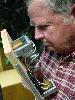
BEC Posted July 16, 2005 Author Share Posted July 16, 2005 Gil, I perhaps should have pointed out a couple of complicating factors. The crossover is not functional now and mine are not the first hands that have been inside it. That is why the usual test methods are more difficult than normal for this crossover. Inside, it is a real mess with evidence of an attempt to get some of the parts out of the tar gunk. Notice for instance broken wire on the upper right. I just figure that someone must have dived into one of these things before and figured it out. I have not been able to find that, however, in some internet searches. Since I work on a lot of Klipsch crossovers, I must say that I am happy that Mr. Paul did not have the love of potting crossovers in tar like some of his contemporaries did. Bob Crites Quote Link to comment Share on other sites More sharing options...
WMcD Posted July 16, 2005 Share Posted July 16, 2005 That is very ugly. What do you make of the orginal use of the crossover. I see -K in the woofer and the odd midrange. Is it an EV variation on the K-Horn? Gil Quote Link to comment Share on other sites More sharing options...
BEC Posted July 16, 2005 Author Share Posted July 16, 2005 Gil, I think it is from an EV Patrician. That may have been the one EV licensed from Klipsch. This is supposed to be a drawing showing the drivers. Bob Quote Link to comment Share on other sites More sharing options...
WMcD Posted July 16, 2005 Share Posted July 16, 2005 Bob, I did some looking around on the web. It looks like it is the crossover for the Georgian. This is the EV standard size K-Horn. The Patrician was the version scaled up to 18 inch woofer, but then it used a total of four horns. Different crossover, natch. In your last post we see a G at the edge of the picture. It must be the first letter of Georgian. We're getting closer. I have some plans for the Georgian at the office and I'll check tommorrow. Do you have "The Trouble with Attenuators" by PWK. The topology of the X over might be there. I don't recall if there are values. Gil Quote Link to comment Share on other sites More sharing options...
BEC Posted July 16, 2005 Author Share Posted July 16, 2005 Gil, That makes some sense to me. I just re-read what the guy that owns this thing said and he has a pair of Georgians and a single Patrician. What I would like to do with this mess of a crossover, is to duplicate it with modern parts and let him try that duplicate back in one of his speakers with the attenuators he has. Then if he can get the right sound out of that, I might convince him to allow the junk to be dug out of this X336 box and I could build the entire crossover with an autotransformer in the box. Or, of course, the crossover could be built on just a block of wood and he could keep the old crossovers for collectable value. If you do find some values for me, I would appreciate it. Otherwise I may have to get dressed like I would to perform a colonoscopy on an uncooperative buzzard and clean it all out so I can tell what is in there. Bob Quote Link to comment Share on other sites More sharing options...
Al Klappenberger Posted July 16, 2005 Share Posted July 16, 2005 Bob, If you can measure the crossover frequencys I can easily compute the values for that network. Just terminate each channel output with 16 Ohm resistors and fine the frequency where the adjacent channel outputs are equal. Al k. Quote Link to comment Share on other sites More sharing options...
BEC Posted July 16, 2005 Author Share Posted July 16, 2005 Al, The thing does not work. Has been messed with at some time in the past and even has loose wires inside it. Bob Quote Link to comment Share on other sites More sharing options...
Al Klappenberger Posted July 16, 2005 Share Posted July 16, 2005 Bob, OOPS! That definitly complicates things. If you can come up with the xover frequency of each channel though, I can duplicate it becasue it's the same dual-diplexer configuration I use. Al K. Quote Link to comment Share on other sites More sharing options...
BEC Posted July 16, 2005 Author Share Posted July 16, 2005 Al and Gil, A thought just hit me. If this is a 16 ohm crossover based on the Khorn of that same period. I would wager it is very close to a Klipsch K-500-5000 network. I happen to have a pristine one of those. What do you think of that idea? Bob Edit, Found a schematic of the K-500-5000. It has to be different. Has only 2 inductors in it. I do think though that the crossover points have to be around 400 to 500 and around 5000 based on the drivers being used and the way the bass bin has to work. Bob Quote Link to comment Share on other sites More sharing options...
WMcD Posted July 16, 2005 Share Posted July 16, 2005 My guess is "no". PWK was into primes and, or odds. 3, 5, 7. The EV crossover points tend to even, round numbers. The EV people did good work. But I think PWK had something else going on. Gil Quote Link to comment Share on other sites More sharing options...
Al Klappenberger Posted July 17, 2005 Share Posted July 17, 2005 Bob, Here's the crossover with values for crossovers at 400 and 5000 Hz. If it's for a Khorn clone, this should be ok. Al K. Quote Link to comment Share on other sites More sharing options...
BEC Posted July 17, 2005 Author Share Posted July 17, 2005 Al, Thanks, do you have the numbers handy for the first cross at 500? Bob Quote Link to comment Share on other sites More sharing options...
Al Klappenberger Posted July 17, 2005 Share Posted July 17, 2005 Bob, To change the cross to 500 just scale the values 17.6 uF and 9 mH by the ratio 5/4 = 1.25. 17.6 becomes 22 uF amd 9.0 mH becomes 11.25 mHy. The inductor values are higher than we are used to becasue it's a 16 Ohm filter. Al K. ERROR: I screwed up! The comutation I did is for a crossover of 320 Hz, not 500! The values should have been multiplied by 4/5 = .80 to get to 500 Hz. Quote Link to comment Share on other sites More sharing options...
BEC Posted July 17, 2005 Author Share Posted July 17, 2005 Al, Thanks, By the way, I found a schematic of PWK's K-500-5000. It was also a 16 ohm network and I think at some time used the same EV 15WK woofer and T-35 16 ohm tweeter that this EV X336 network drove. Bob Quote Link to comment Share on other sites More sharing options...
WMcD Posted July 17, 2005 Share Posted July 17, 2005 Sorry, I don't have the values. It might be that they're kept secret 1) by not putting on the schematic and 2) by potting. You may find the attached helpful in that it describes the crossover points as 300 and 3500. You would think they'd call it a 335. I'll point out the topology is not that of a 500-5000. Note an inductor is shared by the bass and mid. Maybe we can reverse engineer by assuming the designer used a Butterworth target. Gil X-336.pdf Quote Link to comment Share on other sites More sharing options...
BEC Posted July 17, 2005 Author Share Posted July 17, 2005 Gill, Good find. It is sort of a 4 way in a strange way. The use of two horns to cover the range of 300 to 3500 is interesting. Also crossing over to a T-35 at 3500 hz is sort of frightening since I know from experience that very small amounts of power below 3500 will rip the VC of a T-35 right apart. I beleive I have seen some EV add-on tweeter protection modules that were likely made to address this problem. Bob Quote Link to comment Share on other sites More sharing options...
BEC Posted July 17, 2005 Author Share Posted July 17, 2005 Al, Take a look at this schematic with measured values and see if they make any sense to you. Notice that one of the parallel caps midrange filter is not measurable and the other is 21 uF. The other set of caps shown on the woofer side are not there. Bob Quote Link to comment Share on other sites More sharing options...

Recommended Posts
Join the conversation
You can post now and register later. If you have an account, sign in now to post with your account.
Note: Your post will require moderator approval before it will be visible.