twalkonline
-
Posts
39 -
Joined
-
Last visited
twalkonline's Achievements
Member (2/9)
2
Reputation
-
That's right. I have one spare stock K48. I kept the KP301's identical, each with a recone. I did swap the recone out with the stock speaker for a test, to see if I could hear a difference and I could not.
-
Unfortunate situation forcing sale of KP301's. See Houston Craigslist for photos and details. http://houston.craigslist.org/ele/6037938772.html?lang=en&cc=us
-
The 8HD mid horn is an 800Hz horn and in the case of the Eliminator, it did not have the benefit of being mounted to a solid, flat baffle. Therefore the low midrange performance suffered considerably compared to the 400Hz mid horn of the LaScala. Also, it may have been convenient to mount the mid horn and tweeters in the mouth of the bass horn, but there had to be a lot of modulation of the high frequency content by the lows. That can't be good.
-
I have a couple of textured black KP-101's. The tweeter is the K76-K, same as KP-201. I'm not sure but the 8" woofer may have also been used in one of the Tangent series. I also have a professional products brochure which lists available finishes as textured black, textured white, oak and raw birch. A later cut sheet lists the KP-101 woofer as 10" although I think that is a typo. There may also be a version that used the same dhorm tweeter as some of the KG's. I have seen those, but don't have any other info on them. Hope this helps...
-
I'm sure that the resistors are there for some sort of impedance compensation, but it is not a proper Zobel circuit. A Zobel circuit would be the series combination of capacitor and resistor(s) in parallel with the woofer. The KP115 resistors are directly across the woofer, after the low pass filter. I'd still like to know how burning approximately one quarter of the power in those resistors could be a lesser evil than a network without those resistors.
-
Thanks for posting the images, although I think they're going to give me nightmares! Here's what I know: any woofer will have a nominal impedance, but the exact impedance that the amplifier sees will vary with frequency. Thus there will be a curve that describes the woofer's impedance versus frequency. This impedance will also be affected by the change in impedance mechanically when the woofer is mounted in an enclosure. The K-48 is a nominal 4 ohm rated woofer, but the KP 115 and other speakers that use it are rated at a nominal 8 ohms. I get that. What I don't get is why the resistors are in parallel (not in series) with the woofer. If I remember my circuit analysis 101 correctly, current divides in inverse proportion to the values of the resistors in parallel. Therefore, if the K-48 were a true 4 ohms, the 12.5 ohms in parallel with it would see approximately 1/4 of the current and thus 1/4 of the amplifier power would be dissipated in the resistors. If the K-48 were a true 8 ohms, it would be worse and approximately 2/5 of the amplifier power would be dissipated in those resistors. Again, if I'm missing something I would appreciate someone setting me straight. Otherwise, I would appreciate someone explaining how those resistors are a good idea. Thanks.
-
Can anyone tell me why the internal crossover has two 25 ohm resistors in parallel with the woofer? It doesn't look like a Zobel circuit, although I guess it could be an attempt at impedance correction. But If I remember Boylestad correctly, about a quarter of the power going into this thing will be dissipated as heat. No wonder they burn up. Am I missing something?
-
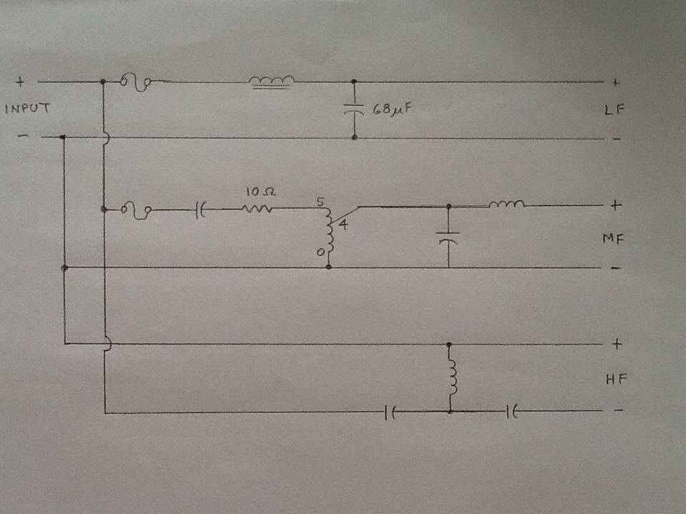
Thanks. It's most similar to the Chorus I, but not exactly. KP has additional low pass filter in the mid circuit. Have redrawn - I think it's correct this time.

-
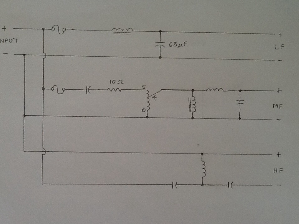
After tracing the circuit, I've determined that the black epoxy potted mystery components have to be capacitors. Am guessing at values. The other caps are labeled 4J. Can't remember how that translates to uF. Hope my sketch of circuit is legible...
-
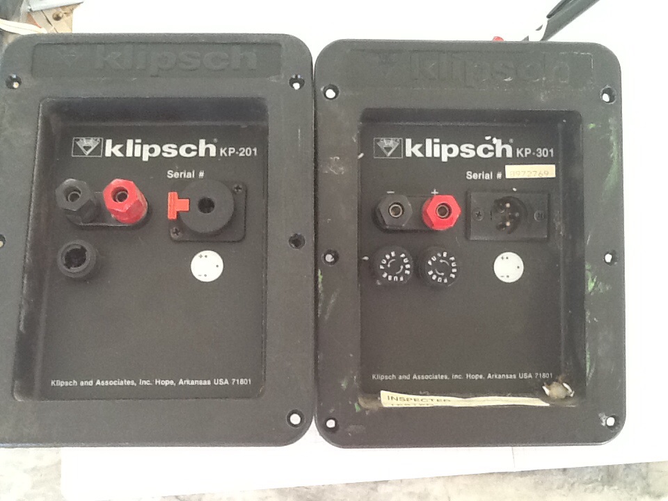
I feel like an archeologist, unearthing things that no living person has ever seen! First, does anyone have a schematic for this crossover? That would probably answer my questions. I found one for the KP 301-II, but this is different in several ways. I expected this one to look like a KP 201, crossover, but it does not. I don't see anything I recognize as a poly switch, although there are a couple of components in the tweeter circuit that I can't identify. They are epoxy potted in little black plastic cases and have no markings. Anybody know what these are? This version does not have separate HF and LF inputs for bi-amping, but it has a separate fuse for the tweeter. Would appreciate comments...
-
Thanks. That's kinda what I expected, but was hoping for something a little less labor intensive. The problem may be the molded plastic collar that holds the mounting nuts. XLR screws are at 3 and 9 o'clock while Neutriks' screws are at 2 and 8. As far as the XLR being factory installed, I have to assume it is. I don't know when this would have been the standard, but the input cups are molded to accept the XLR mounting screws and the overlay has the XLR pin out in the silk screen. This is true with both 201 and 301's.
-
I'm refurbing some KP-201 and 301's. The newer ones have the Neutrik 1/4" which is easily replaced with the NL4 Speak-on jack. However, the older ones are fitted with an XLR which is slightly smaller and has a different mounting hole footprint than the NL4. I have not attempted to cut, drill or punch the plastic input panel as I'm not sure of the best tool or technique to do so without risk of cracking the plastic. On the other hand, I have a new, universal input panel from Klipsch which is pre-punched for any combination of NL4's, fuses, or binding posts. However, This part does not come with the overlay which covers the unused holes and the overlay is not available as a replacement part. Anybody out there have any experience with this and can offer an opinion on what is the lesser evil? Thanks
-
In search of lonesome KP201. Can be dead or alive, in any condition or stage of completeness. Will consider a pair if the deal is right. Lemme know. Thanks.
-
Professional Equivalent to the Heresy
twalkonline replied to chisoxpurdue's topic in Klipsch Pro Audio
You may find some "industrial" Heresy's w/ standard components and specs, but w/ fused input panel and industrial trim. HIP is Heresy Industrial Ported. LF response is only good down to about 90 Hz, but sensitivity is about 100 dB, as opposed to 96 dB of std Heresy. KP201 is "industrial" Heresy II. Has additional tweeter protection, pro input panel, and plywood cabinet - slightly larger than Heresy II w/ internal bracing. KP250 is ported version and like the HIP, sensitivity is 101dB, LF response down to 90Hz. KP301 is "industrial" Chorus. Same components, but w/ tweeter protection, plywood cabinet, pro input panel. See earlier posts for differences between KP201 and KP201 II. Hope this helps -
As far as subs go, I'm not a big fan of subs in general, but I did want a little more low end than the 201's can deliver. The KP-115 works OK for me (I also use it with some KP-101's occasionally) but I recognize it's shortcomings. I bought it for it's compact dimensions, as I'm sure many people do. I haven't tested it,but I don't think the sensitivity is any where near the published 101dB. I've also seen a lot of blown ones on the used market. As far as the bridge goes: I have a proper line level mixing circuit with volume control feeding a separate amp. But thanks for looking out for me!