


gnarly
-
Posts
88 -
Joined
-
Last visited
Content Type
Forums
Events
Gallery
Posts posted by gnarly
-
-
22 hours ago, NBPK402 said:
I am working in a 2' (approximately) cube MEH. It will be using my EV DH1A driver and most likely a pair of Emminence Kappa 15C woofers (same as my k402 MEH). Hopefully it will compare well. I am planning on it being built out of 2 layers of 3/8" bendable plywood, but we might do it out of kerfed plywood. Time will tell as to which is easier, and less expensive to build (I do not want this to get more expensive than a k402 or the only benefit will be size). I might also build a sub to go under each cube to get down low for movies too. It would most likely be a seperate box custom folded horn...with the MINI on top.
Sent from my SM-T830 using Tapatalk
Sweet project !
Please post how you end up laying out and cutting the curved plywood, to get it to match together in the flared corners. This is so hard for me to visualize how to do.
I've had a heck of a trial and error process time with my attempts at any kind of curved secondary flare / horn walls.
Are you using the Bwaslo spreadsheet for starting design?
-
 1
1
-
-
1 hour ago, Supersteff said:
Hi Gnarly. I'm just guessing here.
Are FIR-filters always with the same delay? Maybe the lower the crossower-frequency the longer the needed delay, due to longer wavelenghts? My thought is, that the delay is given by the high-pass-crossower-frequency, in your case 100 Hz. You could check that hypotese, by creating high-pass-filters with say 200 Hz, and see if the deley gets shorter/lower or stays the same!?
Hi Steffen, like Edgar said, a FIR-filter can be made with whatever delay you want.
The delay is simply a function of the size of the filter, it's sample rate, and where in the filter the impulse-peak is placed. (Linear-phase centers the impulse peak; IIR replication puts the peak at or very near the start)
Which makes the delay independent of xover frequency. Xover frequencies can be moved up or down with no effect on measured delay.
So in the experiment you propose, delay will not change at all moving high pass from 100Hz to 200Hz. A really helpful tuning property, huh? 😀
I've come to realize the difference in delays measured, using linear-phase tuning on a number of conventional multi-ways, has always appeared to equal the physical distance between acoustic centers. I say appeared because it has always looked close to what would be expected geometrically.
Not so with the MEHs....i can't wait for someone smarter than me to tell why MIDs closer to the mic, measure further away than the more distant CD.
QuoteI think that for lower frequencies you need more taps, and more taps make more delay. Is that correct?
Steffen
Yep, again like Edgar said. Basically, it takes time to fix time. So more taps are needed, doubling per every octave decrease.
Higher order hpf's and lpf's, as well as higher-Q Eqs, also need relatively more taps.
-
2 hours ago, Supersteff said:
Hi Gnarly
Well I kind of thought of you, when I wrote "somebody" 😄. It seems you are pretty skilled in building horns. I hope to become skilled to, but have some issues preventing me from starting up my synergy-projects.
Interesting to see what you come up with. I think it is important to think thoroughly about the design of the "experiment" to really know what you are looking for. As said, I´m most interested in Danley-style ports.
On the other hand, I have contemplated to build a horn your stile (one woofer top/bottom in between the walls), but with two smaller woofer-ports instead of one, i.e. like a compromise between Danley-style and Gnarly-style. That way the port would not be in the center and the ports would be smaller!? Dunno if that is a good idea?
Can this be caused by a phase-shift/delay caused by the acoustic low-pass-filter of the band-pass-enclosure that the woofers are playing through? I think Tom D hinted at something like that once.
A lot to learn! I really appreciate this learning environment/forum and the people contributing with knowledge and experience.
Well this thread has partly developed into some sort of learning/understanding thread for Big MEH´s, so I don´t know where else to put it? Most of the threads started by Chris tend to develop into educational threads going in all sorts of directions, answering all kind of questions in regard to MEH´s! Maybe start a new thread for "Experiments and explorations of the MEH-concept"?
I think we are quite some people following this thread, that do not have access to K402-horns for different reasons (me living in Denmark, Europe), but are inspired by the K402 for some kind of DIY-solution like yours.
Steffen
Hi Steffen, yeah I though you might be throwing me a hint haha. 😄
I tried putting ports more to the corners/side using the top and bottom style. It didn't work very out compared to center. I also tried a centered frowny face arc, close to the throat, almost under the surround.
Kept finding improved driver response when centered, withoutout significantly more polar damage . But I'm sure there's more to be found out here still.
I don't see how the delay measurements can be caused by an acoustic phase shift, but since i don't know what causes the delay anomalies, i can't rule acoustic phase shift out.
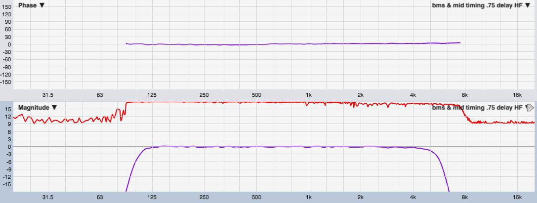
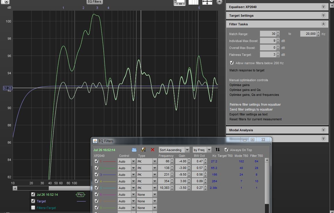
I'm pretty dang certain it isn't electrical xover induced delay. I just ran some quickie measurements to illustrate.
First measurement is Syn7's processed 10" mid cones a meter or so away from mouth.. The timing delay was 178.94ms,
which is the sum of processor latency and time-of-flight. (I did say I use alot of FIR Lol)

The next measurement is the lower section of the BMS CD being used, the HF, . It had a delay of 177.29ms.
And is further away from the mic physically !
Please note the flat, linear-phase, phase traces for each.
When phase is zero degrees flat like that, the delay needed to time the sections together is simply the difference in measured delays.
Which in this case is 0.65ms.
So the last measurement is both sections MID & HF together, with a 0.65ms delay in place for the HF CD section (to match up to the MID's measured delay)
It's really as simple as that to establish delays when working with true linear phase. A relative pure joy.
The 0.65 ms needed to add to the CD's HF section is what puzzles me...that's nearly 9 inches of delay.
Right now I'm inclined to think the CD's apparent acoustic center is moving out into the horn....but plain dunno...
-
1
-
-
22 hours ago, Supersteff said:
I have been wondering for some time, weather it makes a difference, where the off-axis-ports are located, i.e. on the sides or top/bottom? How does it affect the horizontal dispersion?
In other words, would it be a good idea to place the woofers top/bottom, so that the off-axis-ports disturbances are moved from the horizontal to the vertical plane?
Suggestion for an experiment:
Someone builds a 60x60 horn of reasonable full-range MEH size, mount a CD and woofers on two opposing sides and then measure polar response vertical, horizontal (and maybe even diagonally?) with and without off-axis-ports drilled (like Gnarly did). There are of course at least two options for the placement of the off-axis-ports, Danley-style and Gnarly-style. I´d prefer to see the results for Danley-stile off-axis-ports. That experiment could potentially be very educational if carefully designed.
Maybe there could be some group-funding per PayPal to pay for some sheets of plywood?
I am not in a position to execute that experiment.
Steffen
Hi Steffen, I'd offer to take up the project, but I learned along time ago that a good way to ruin a hobby is take any kind of money for it. 😅
With what you proposed, a 60x60....if it has ports in the corners as traditional, i think it's going to be very symmetrical and won't show much, if any, H vs V variation.
If the 60x60 used my center port design it might indeed have H vs Variation. I've never tested center ports on anything other than 90x60 and 75x50 patterns, and to be honest haven't really cared about their Vertical polars.
A thing to be aware with the big mid drivers on top or bottom, is that the design requires H to V asymmetry to fit the drivers in between the side walls(like in pict i posted)..
1.5:1 or higher works for 10" or smaller. Don't know yet what 12"s would need....it would need to be very big, or have a higher aspect ratio.
You are correct about the design fitting in a corner better that side mounted and enclosed...in fact it will fit much better, especially for a 90 H pattern.
I've got a large room i keep toying with the idea of putting one in each corner up high. If it weren't for the CD, the horn walls could go flush against the room walls!
But all that said, maybe the place for this discussion is in the newly formed less-than full range MEH thread ???
I think Chris would like to keep it focused on k-402 builds here...
-
On 5/3/2021 at 2:50 PM, Chris A said:
I was describing the changes in acoustic behavior as the frequencies decrease (i.e., the wavelengths are increasing) to where the distance from the throat to the beginning edge or lip of the off-axis ports is several wavelengths, then eventually it's at one wavelength (i.e., an acoustic impedance bounce--generally attenuating, and eventually the wavelengths correspond to a half wavelength to the horn throat (generally a resonance frequency), and then finally a quarter wavelength (where there is strong attenuation/ cancellation).
At shorter wavelengths, the side walls behave more like canted outward mirrors as in optics. At the one wavelength, half wavelength, and quarter wavelength points, the idea is that the horn volume behaves more like a resonant chamber and the volume geometries become important, not just the side wall area presented. Remember that a horn is first and foremost an acoustic impedance transformer, then it can be viewed as a acoustic wave director--creating directivity in the emitted acoustic energy field.
At the first notch frequency of the woofers, you're seeing 1/4 wave volume resonance effects (very distantly reminiscent of a Helmholtz resonator). But what the behavior actually changes to is a function of the exact geometry of the throat-end section of the horn bounded on the outboard side by the lip of the off-axis ports. If those port edges or lips happen to be located at a pressure (or perhaps velocity) maximum for the resonant waves going by, then more disruption and attenuation occurs. So the idea is that the pressure waves (or perhaps velocity waves) are maximal at the middle of the horn walls (but perhaps not, depending on wavelength). For the geometries of the horn used, perhaps the local pressure or velocity max regions shift toward the creases or internal edges of the horn. So it isn't really clear what the dynamics of the acoustic waves are actually doing around the off-axis ports--it's probably complex.
The first bet, however (i.e., Occam's Razor) is that the mid-walls are where the influence from the side walls is minimal, and therefore where you don't want to put a penetration through the horn wall. That's the reason for avoiding placing the ports at the midpoint between the walls.
However...
Chris
I'm happy to say i understood most of all of what you said. Thanks.
I've poured through the patents and many various Synergy/MEH forum discussions, and questions seem to come down to how well do the theory pieces match the results.
I don't doubt any of the the known physics in play, it's just how the pieces actually play together seems more complicated than describing how a MEH works piece by piece.
It's like the drivers see each other, as well as the horn, and their combinations of interplay form new "virtual" acoustic drivers and centers.
I've learned how important it is to short out the drivers not being measured. For instance, not shorting even the CD when measuring the mids, will put significant ripple in the mids' measurement.
The mids i've used to reach to the CD have been either a pair of 8, 10, or 12" drivers. The ports centers, off-axis for the 12"s, and centered for the 8 and 10"s, have all been in the vicinity of 5" from the throat. I've tried to keep 1/4 WL notch at least above 600Hz.
Funny thing is, the time-of-flight (ToF delay) to acoustic centers of the mids, has always been greater than the ToF to the CD.
Funny because, even the mids' voice coils have less physical distance to the mic, than the CD does. Mid ports have obvious less distance still than to the CD . Dunno.....
A technique I've begun using to explore the interplays and timings, is using one driver as a microphone, and another as speaker.
And then measure via normal dual-channel or pulsing a wavelet (a recently learned method that has high timing precision on a frequency selected basis.)
Idea is to measure the time seen between the drivers and compare those "inter driver" flight times, to the difference in regular microphone at listening distance ToF's..
So for example, I've used the CD as a mic, and stimulate the mids. Then reverse that. Then do one mid as mic, one as speaker, .....etc...
We'll see...could be a waste of time, but we'll see....
-
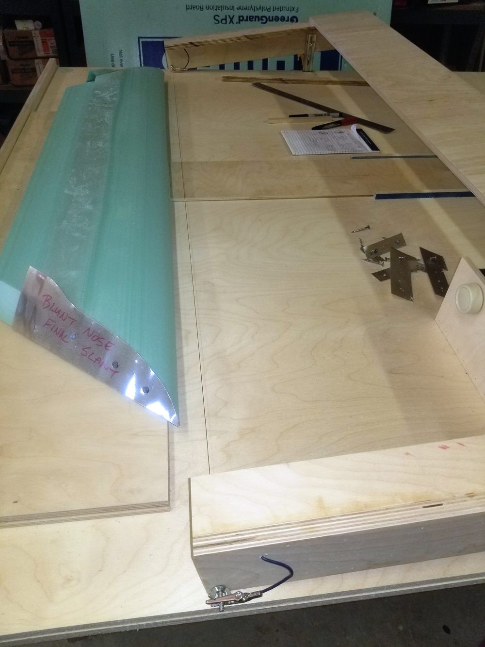
16 minutes ago, Khornukopia said:
How is that constructed?
I made flares out of 2" thick XPS foamboard.
Here's a pict of one in progress, and the big hot wire knife used to form them.
Idea and how-to credit, goes to a member named Oohms....found the link to his project somewhere on these forums...
-
1
-
-
That's some very nice directivity,, and a great looking audio room!
I guess what's been puzzling to me in this thread, is that i thought it's about finding a suitable substitute for a less than full-range K-402 based MEH ... like using the SEOS-30 in the thread starter. Then later, i think your take on the JBL2384 kinda threw me. It seems like it might be very similar to the SEOS-30 in terms of MEH suitability. So I was surprised and i probably pushed back a little in favor of encouraging smaller MEH explorations.
Anyway, we are all of course entitled to profess our thoughts and preferences in any civil way we like....and i think it's nice to see someone like you so dedicated to a platform you enjoy so much. (and helpful to others)
Yes, my interpretation of linear phase is flat phase, flat as in a line. Same interpretation as the rest of the world, wink
Linear phase is a straight line against frequency when freq is on a linear scale, sloping when there is a constant delay in the measurement, and level flat at 0 degrees when the constant delay is removed.
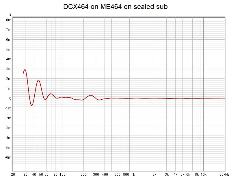
Your group delay plots do look quite good for a passive. Nice !
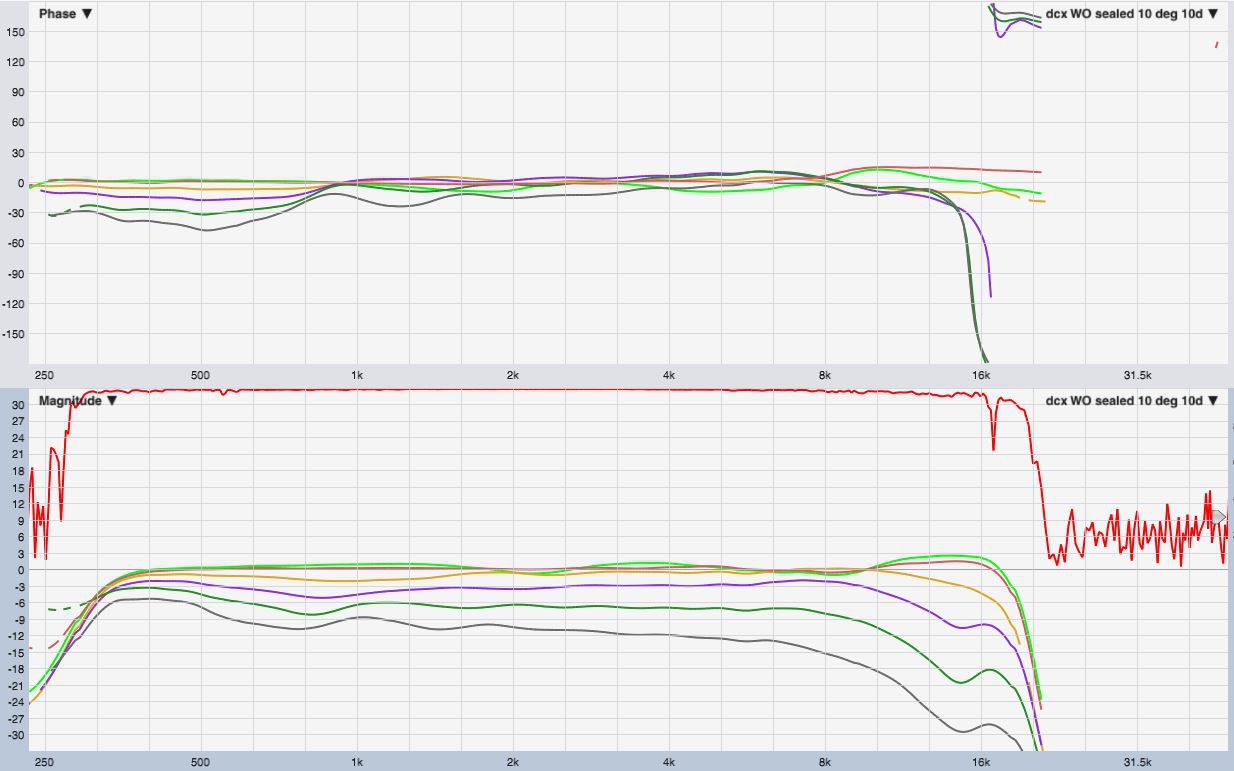
Here's a typical example I get with FIR. This is the group delay of a project i'm working on now, the B&C DCX464 on the ME464 horn....on top of a sealed 18" sub crossing to the CD at 300Hz. (still have something not quite right there below 300Hz).
As you can see, group delay can really be taken way down...
-
6 hours ago, Chris A said:
That's because is only has 50 degrees of coverage horizontally (or vertically). You need two stacked together side-by-side to have the same coverage as a K-402-MEH. But there seems to be some folks that have such small (or terrible acoustics) listening rooms, that they prefer that extremely narrow coverage.
As a matter of course, Klipsch designs horns to have 90-degree horizontal coverage horns--basically all of them. There is a reason for this. I should add that the default coverage requirement (above) is 90 x 60 degrees. If you decide you need narrower coverage--that's certainly up to you, but my experiences are that it doesn't have "apparent source width" (ASW) that fills the front of the room, and without loss of directivity control.
It does if you want to call it horn-loaded, i.e., that it has directivity down to at least 200 Hz (or below the transition frequency of the room). Otherwise, it's a "hybrid horn--direct radiator" arrangement of drivers that gives the impression of a point source, but in reality is illuminating everything in the near field below the point of loss of directivity control. You can can it an "MEH", but at some point, it's just another direct radiator loudspeaker with a horn-loaded top end.
With directivity control? They're not really "horns"...but more like a D'Appolito arrangement of drivers below the point of loss of horizontal directivity control (after loss of directivity in the vertical axis). Some folks might be satisfied with that. I wouldn't call it a "horn", however.
This: http://www.tonmeister.ca/wordpress/2015/10/29/bo-tech-uni-phase-loudspeakers/
Then I think that you've not experienced a lot of linear phase loudspeakers having passive crossovers and full-range directivity (horn loaded). That's what Tom D. achieved with a fully horn-loaded loudspeaker, but almost no one has picked up that it's the cause of them sounding so special. Tom apparently hasn't been able to break through the tough hide of "audiophiles" that full range directivity combined with linear phase transfer function response (in a loudspeaker having passive crossovers only) yields the "Synergy horn" sound quality that captivates so many listeners.
Go ahead...separate them...if you feel it's necessary.
I think that I'll elect to have full-range directivity control down to the room's transition frequency (i.e., at least down to 200 Hz), and 90 x 60 degree coverage. BTW: vertical coverage can be less than 60 degrees, but typically not without incurring pattern flip at some higher frequency that's too far from the room's transition frequency. Vertical coverage can be too narrow, too.
I think that D'Appolito arrangements are useful, but not really "horn-loaded". Acoustic coupling of drivers without using horn loading is still direct radiating drivers.
Then you will be a fan of the type of loudspeakers described in this thread.
For me, there is too much that's lost with this approach--that otherwise significantly adds to the listening experience...when listening to full-range MEHs...(i.e., also having 90 x ~60 degree coverage as a constraining requirement).
Chris
i think maybe we are needing to agree to disagree.
You're definition of an acceptable MEH/Synergy, seems to require 90 deg horiz coverage and provide pattern control to at least 200 Hz.
Using Keele's pattern control formula, that would require about a 46" wide horn, which i believe is about half a foot wider than even the k-402....which means the k-402 has to go in a corner to get the desired directivity. So it appears your definition of an acceptable MEH is narrowed down to what you have and like, including an accommodating room.
My definition is simple......imho a Synergy is a horn or a waveguide that has multiple drivers mounted to it, that cover different frequency ranges.
"Horn-loading" is an important aspect, but not essential throughout the design's frequency range, as all horns let go somewhere, even the larger than norm k-402 and my 49" wide conical DIY. (i do want to try 60" wide outdoors this summer, on top a bank of TD's Labhorns
I get what you mean by the mids on the SH-50 acting as a 'phase link now, thanks for the uni-phase paper. I've seen that technique before for putting together 2 order Butterworths , and it could be a part of the SH-50 xover design...who knows.
Tom D recommended LTspice to me for passive xover work, maybe that would be of value if you like to explore passives and what he might be doing, deeper.
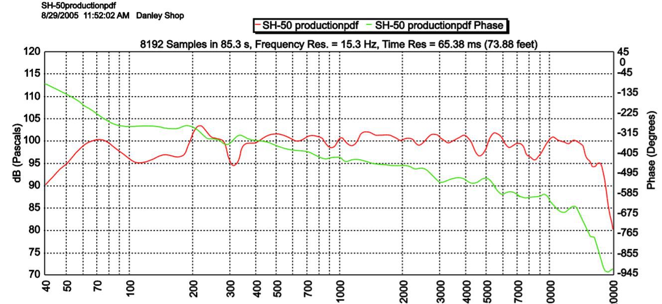
I told him I'm multichannel-active rephase/ FirDesigner all the way, and he smiled and said he used rephase to phase flatten his SH-50's at home.
Which btw, the SH-50 is not even close to being a linear phase speaker. I mean, look closely at the attached phase scale....look at all the phase rotation.
Yes, I do think I've heard horn-loaded linear phase speakers with directivity below 200Hz. My current Syn7's do that.
And I mean true linear phase, something that is pragmatically unobtainable with multi-way passives.
The sound is plain awesome for me, a magical clarity like really good electrostats, and with super transients and dynamics.
I attribute most of the magic to the acoustic co-location of drivers, that the MEH design allows.
T say again, i believe far too much emphasis and speculation about the great synergy sound has been put on their (to-date) passive xovers.
I have the Danley SC-48 speaker processor that has DSP presets for their speakers. There are correction EQs for every model including the SH-50. Models that have bi-amp capability, in addition to passives, use standard xovers.. some even have a 4th order linear phase xover option.
The upcoming 4-way Hyperion is blurbed as 3-way FIR active, with a passive only between the CD and 5" mid.
Imho, xovers are simply a necessary component/problem to overcome.. with the least phase wrap possible.
Anyway, i personally don't feel it's appropriate to narrowly define what a MEH is....or rather, define what it needs to be as acceptable for great listening.
I feel more comfortable just relaying what I've found to work, and what i like about it...
-
3 hours ago, Chris A said:
Well, I think that the SH-50 is most definitely a "full range MEH"...
What I'm referring to, above, is MEHs whose on-axis SPL can't make it down to 100 Hz in half space (or perhaps even quarter space). The SH-50 has a -3 dB (f3) point of ~50 Hz. If you look at all the other larger Synergy horns (of which the SH-50 is one), their f3 frequencies are generally at or below 100 Hz.
When the MEH has a -3dB roll off at 300 or 400 Hz, then all of what I said above applies.
This is where the waters part in our assessments. I don't see a lot of reason for those type of MEHs, to be honest.
Are you aware that you have to cross over to a separate (and usually direct radiating) bass bin at ~400-600 Hz? That's why I said that the 4722 is a better deal, and much simpler to implement. Doing an MEH that only goes down to 400-600 Hz is instead much easier and better done (from many different points of view) in a single 2" compression driver on the same horn--without extra drivers. The reason for the extra drivers--like the midrange drivers in the Danley--is the added power handling of the midranges to alleviate the load on the high frequency compression driver (a 1" BMS compression driver). Danley also uses the midrange as a "phase link" driver with very narrow bandpass in order to facilitate its use of passive crossover filters for fixed PA duty. That's not really a home hi-fi requirement.
I'm not sure what you are saying here. Could you be a little clearer in what you're saying?
Well, if you just like to tinker, that's certainly okay. But I wouldn't waste much time on that sort of thing, to be honest.
Chris
I guess i don't see the SH-50 as a larger Synergy, as the entire frontal box size is 28"x28".
And I know it doesn't take a big Synergy/MEH to reach below 100Hz, other than for how loud do we want.
Can't say i've ever seen anyone build a MEH that didn't get to down to at least 300Hz...in fact i'd say it's almost impossible not to.
Even the little 3"s and 4"s tied to a CD will do that.
And it's very rare to see a DIY MEH that doesn't also have a woofer(s) to go with smaller mids, taking response to at least 100Hz or below.
I totally get and agree with what you're saying about the mids being the added power handling to the CD, but i'm not sure what you mean by the mids being a phase link.
I think too much has been made of the Danley passive xovers...they seem pretty normal to me, especially when you look at the SH-50's phase trace scale...not quite so flat then. Lol.
I guess what I'm trying to say, is we need to separate the size of a MEH and its subsequent pattern control , from the response of a MEH and its sonic benefits from close coupling drivers.
I think the sonic benefits are great enough to pursue any MEH that gets within reach of a sub, no matter how small the MEH.
But at the same time, i also acknowledge that sonic benefits get amplified with lower pattern control from a larger MEH...which i take is your viewpoint.
-
3 hours ago, Chris A said:
My next question would be: "why go to the trouble of doing an MEH on top--why not just use a 4722"?
Perhaps by now you might see why I want to break these types of MEHs into a separate thread. There is a lot more head scratching going on when the horizontal horn dimension is less than 35-40 inches (the actual mouth size--not the horn flange size). You begin to question why you're going to all that trouble to avoid spending a few hundred bucks.
If you're right on the edge of not being able to afford good horn-loaded loudspeakers of the full-range MEH design (i.e., the K-402-MEH), you'd be doing bottom dollar on the compression driver, woofer(s), and DSP crossover, and having to live with the system noise floor to do that (or playing with resistor attenuation networks to drop the noise floor from the DSP crossover).
I think that working an extra couple of weekends for overtime pay (if an hourly wage employee), not going out to eat for a while (i.e., bringing your lunch to work, etc., or doing dinner at home instead of fast food runs, etc.), or cutting down on your cellphone bills by cutting back the "bells and whistles" extras tacked onto your bill would be a key enabler to get a setup that avoids all these issues.
Chris
Must admit, your reasoning does not make sense to me....if i understand it correctly.
You seem to be saying, unless you go all the way to a very large Synergy/MEH, there's no point going at all. ????
If that were true, there would be no point in the SH-50, or any of the small-syn DIY builds people have been pleased with.
To directly answer the question "why go to the trouble of doing an MEH on top--why not just use a 4722"?
I would say to gain the coherence of moving closer to a point source, regardless of where it looses pattern control.
I would try to mount some big mids on the 2384 horn just to gain coherence down as low in frequency as possible, again regardless of where it looses control.
Tightening up c-2-c's of any and all drivers simply works ime. And that's what MEHs do best, big or little, imo.
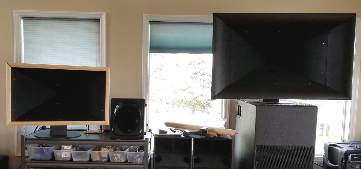
Right now I'm running listening tests on the same Syn7 horns, where one has only 1.125" quarter round for mouth termination, and the other has tractrix like mouth flares.
Tuning/processing is identical for both.
The larger Syn7 does have a fuller richer mid bass sound. But the smaller one can be EQ'ed pretty dang close...
and the real point is, the smaller one is still one of the best speakers I've heard. (maybe the second best Lol)
So my advice is, heck yeah, build small syns too !
-
1 hour ago, Chris A said:
"In God we trust...everyone else bring data".
Do you have some polar sonograms of the differences? I would be extremely interested in seeing that data. That's a lot of work that can be shared or perhaps leveraged with others tackling the same MEH design problems.
Some of the above leads me to believe that there is a fair amount of guesswork still occurring without a full study of the effects of where to put the woofer/midrange ports and how big/their shape should be. (I.e., if what you say is true, then Danley isn't putting the ports in the corners of the horn for polar consistency purposes--which I do find both interesting and hard to believe.)
There is quite a lot going on in terms of frequency-dependent reflections (like optics) and less-than-half-wavelength volume and area support of the developing waves going (like horns operating near their axial 1/4 wavelength frequency or operating loudspeakers below the transition frequency of a room), with a seamless transition between the two right around these extra (non-throat) ports.
I suppose you have found that crossing the lower frequency drivers to the higher frequency ones actually require a bit of overlap (or at least a "zero lap" on the 1/4 wavelength from the throat entrance plane (i.e., not the acoustic center of the attached driver). I believe that each MEH DIYer is rolling their own, and not really discussing the tradeoffs of where to cross. I've found that crossing the higher frequency driver right at or just below (in frequency) to the natural bounce frequency of the lower frequency drivers smooths out the phase and SPL response, and the polar response (to some degree).
Chris
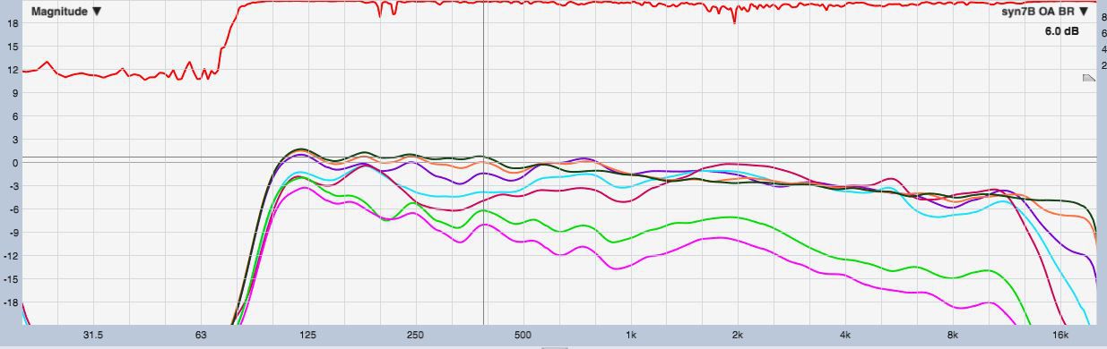
Here's some horiz polars that uses two 10" woofers with centered ports as shown in previous pict. It's a 90x60, 48"x29", build.
10 deg increments. Black is on-axis. Downward sloping response is intentional.
For polars of builds with off-axis ports, i'd like to refer folks to https://www.diyaudio.com/forums/multi-way/340480-100hz-synergy-project.html
It was the thread i started that has the early MEH protos, all with corner ports. Polars are scattered in the thread. I found some on page 5 & 8.
I'd post some here, but would have to dig through an old balking laptop.
I completely agree as to the amount of guesswork floating around. I have a number of things in mind to try still, about stuff i plain don't understand like how the big mids consistently measure further away than the CD.
It's clear to me you understand the physics of what's going on much better than i. But i keep learning...
I've found i can cross about anywhere in between the intersection of how low will the CD go, and how high will the big mids go.
So that typically means anywhere between 450 to 700Hz. I let polars do most the decision making.
It's a real beauty of steep linear phase xovers imo, being able to move xover freq easily leaving frequency and phase response unaffected on-axis. After moving xover, i just see how well it holds up off-axis.
That said, I do want to more thoroughly check out polars with shallower slope xovers .
-
On 3/31/2021 at 9:33 AM, Chris A said:
The problem that arises in placing the (off-axis) woofer ports across the middle of the horn walls is that it degrades the most important loudspeaker capability: consistent polar directivity/coverage. The reason why Danley places these ports in the creases or corners of the rectangular or square horn is that their placement degrades the polar directivity at the frequencies associated with the crossover region (otherwise called "sound power smoothness" in the pie chart below which is condensed down from Sean Olive's linear decision model for loudspeaker preferences--US 8311232)--which is the most important determinant of loudspeaker preference (i.e., more important than flat on-axis SPL). Placing the woofer port in the middle of a horn wall is absolutely the worst place you can put them, IMHO:
Apparently the guys over on diyAudio don't let little things like that bother them...
My woofer ports take after Danley's Synergy and Unity horns, both in their placement and their size.
So the area placement and magnitude of the off-axis (woofer) ports is a tradeoff variable. This is one reason why I set the 10:1 "compression ratio" of woofer cone area to woofer port area, which is high n terms of horn compression ratios. The reason for keeping this compression ratio under 10:1 is the preserve the efficiency of the low frequency portion of the horn, which is directly affected by the compression ratio used (i.e., inverse relationship between compression ratio and efficiency).
Chris
The new thread "Nearly Full-Range MEHs" inspired me to check out the last few pages of this thread, and i saw this reply in regard to my placement of woofer ports in the center of the horn, rather than in the horn corners (off-axis ports ).
I have not found ports in the center to degrade consistent polar directivity/coverage. Surprisingly not, given the nearly universal opinion that they would.
In the first year of building MEH prototypes, i kept ports in the corners like seen in all of Danley's Synergies. I called the prototypes Syn1, Syn 2, etc.
They developed into Syn5, which was my first "built to keep" MEH. All along the prototype process, I measured the polar response of the horns without any ports in them to be able to see the effect the ports would have on polars, once the ports were in place.
I should stop and say, all my MEH builds have been with a CD that can go low enough to crossover straight to a pair of 12"s , without any additional smaller mids. And all cross to a sub at 100Hz. (Before beginning any prototyping, I had the opportunity and pleasure to discuss my plans with Tom D at a trade show a couple of years ago, and ask him questions . What a nice helpful guy !!!)
Ok, continuing on... Syn5 with its off-axis ports was (still is) a huge success for me. Great sound, with nice polars.
But it was very heavy, with the woofers mounted on the horns sides, enclosed in cabinetry to form a big box. By the time I added secondary flares, the speaker became unmovable without some disassembly. Since much of my listening and testing is outdoors, the big guy became a bit of a PIA to move in and out.
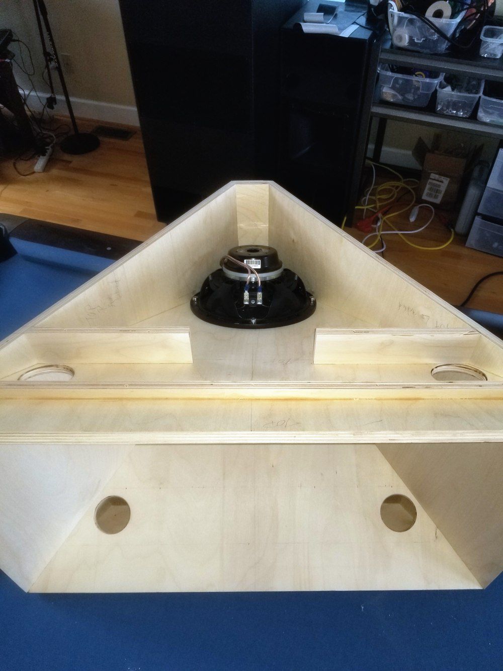
So i started scratching my head on how to save weight, and the idea hit me that if the woofers went on the top and bottom of the horn, a natural way to seal them up existed without having to build a box around them. Like in this pict.. (which is using an 8" woofer) (The ports way out in the horn are reflex ports.)
But as you can see, this precludes putting the ports deeply into the horn's corners.
So i decided to stop and do some feasibility testing with regard to port sizes and placements. I first made a simple test box, like a normal speaker, where i put a plate with the port in it over the driver to measure response. A single center port easily and always, had the smoother response as well as higher extension, than ports moved out towards or even partially under the surround. I kept total port area a constant 1/10th Sd wherever located, and however shaped.
I then know if i can, i want a center port. But will it mess up polars?
I build another horn without ports, measure its polars, then put the round center ports in the horn and measure again.
Heck yes!! I find i can get polars nearly as nice as when using off-axis ports!
My current belief is that the reason DSL puts ports in the corners is about minimizing their small mids' port distance to the CD to get their response to reach up to the CD.
And probably just as big a reason, is actually getting 4 of the dang things to fit in the box along with woofers.
Maybe the small ports closer to the CD throat have a truly disruptive effect on pattern, i dunno at all.
But i do know bigger woofer ports, with centers at 5"+ from CD don't seem to mess up pattern more so than corner ports.
Mouth termination, secondary flares, etc...appears to matter a great deal more to straight-sided conical horn polars.
(The pict eventually became Syn8. So far my favorite is Syn7, the same style box, that uses a pair of 10"s.)
-
1 hour ago, Marvel said:
I have some K-400 horns where the molds were starting to deteriorate... had awful ridges, etc. I've filed most of them out, smoothed them quite a bit. They aren't all like that, most were smooth from the factory.
Depending on how close to the throat they are could make a difference
Gotcha. I do everything i can to keep stuff smooth too. Not so sure how much it matters to the sound, but there's no way i can keep from doing it !! 😄
-
1 hour ago, Chris A said:
The horns with slots that cause frying bacon sound are like the old Altec, etc. "constant directivity" horns--which is the reason why most of us here don't use that term any more in favor of the term "controlled directivity"...straight-sided horns without slots in the throat--like the K-402 and the K-510 series, etc.
I always hesitate to talk about this issue, because then all the Geddes "HOMs" people tend to appear to poo-poo any discontinuities in the horn throat, in favor of "OS" (oblate spheroid) throats. I'm aware that OS throats also have their issues (that Geddes talks about..but not as if they're defects, but rather as "...well, you don't want to listen to your horns on axis anyway...", which is BS).
Make no mistake--the OS throated horns have problems, too, especially because you really can't listen to them on-axis, i.e. the polar coverage of a 2" throat horn above 6 kHz is most strongly a function of the driver's phase plug design, and not so much the horn--unless you stick a throat lens in to spread out the polars (like Roy is proposing with the "new Jubilee"), but then you've got some big discontinuities in the throat again like the old constant directivity horns, and those old horns don't sound very good above 4 kHz (i.e., the horns having 2" throats). It's 8 kHz for 1" throat horns. That all reminds me of the old JBL horn lenses of the 1950s-70s, that were eventually abandoned in favor of slotted throat and baby butt designs of the 1980s.
So it's the degree of HOMs that are generated that is the issue. With OS throat horns, I think Geddes goes too far. With the old Keele constant directivity horns, goes too far in the other direction. I think that there is a range of designs that are "happy mediums". I tend to avoid slots in throats, but that's because of the poor experiences with the D.B. Keele CD horns of the 1970s-80s.
Thanks for sharing that horn info. Interesting thoughts/takes.
What i find very puzzling with the horn measurements I've taken, is throat anomalies such as less than great CD-to-throat matching, diffraction slots, etc....seem to matter less than mouth termination changes. And by less, I mean a lot less. Maybe this is due to working with straight sided conical MEH's so much, trying different secondary flares.
But even on something like the well known elliptical XT1464, a CD to throat mismatch has made nearly no difference compared to the effect of the baffle or box i put the horn into.
Also use a RCF HF950 with a diffraction slot which measures and listens very well. I simply dunno what to think, if diffraction slots are harmful of not.
-
20 hours ago, Marvel said:
That casting needs to be smoothed out where the slot joins the flair. That can't be good the way it is in that pic.
I think that's probably a bit of a photograph optical illusion.
Mine photographs close to that look, but feels and looks to the naked eye, as much smoother.
-
20 hours ago, tromprof said:
Thanks for posting your results. Any subjective impressions on sound?
Welcome !
It's pretty nice sounding. Has a very traditional sound to it, rich in the low-mid and mid ranges (as defined by REW, 300-2k).
That may be due to the way VHF (REW Brilliance) rolls down off-axis. I think the roll-off is steeper than the B&C polars show...https://www.bcspeakers.com/en/products/horn/1-4/0/ME464
Must admit, It's hard for me to make decent subjective comparisons anymore...I've become such a large-size Synergy addict, spoiled/preferring their type sound, that almost nothing sounds really good in comparison. I think if i didn't have the Syns, I'd most likely be very happy with the me464.
-
1
-
-
On 4/30/2021 at 7:05 PM, Chris A said:
A much better shot...
I've also found that it's the length of the cavity behind the slot to the throat of the horn which contributes quite strongly to the "frying bacon" sound. I'm not sure of the length of this resonance cavity behind this slot. If it's very, very short, there may not be a lot of issues with the frying bacon sound.
Chris
The length of the slot is about 7 inches, from the CD mounting surface to where the slot opens into the horn mouth.
Haven't heard any frying bacon yet, but all my listening has been done fully processed...so that might be a factor.
-
1 hour ago, Chris A said:
Wow, I didn't see inside the mouth (i.e., they seem to be hiding the fact that it's got a diffraction slot):
That means that above ~5.6 kHz, you're likely going to hear higher order modes (HOMs) to some degree, depending on the abruptness of that slot transition to the rest of the horn.
Not cool to hide the slot from prospective buyers...Parts Express.
Chris
Yes, the diffraction slot was a surprise to me. Although looking back, in fairness to both PE and B&C, it's pretty clear with a close look. Especially with the B&C Drawing schematic.
One thing that has me puzzling bigtime....is the vertical polars I've measured have been better behaved than the horiz !
But so far, my vertical measurements have only been inside. No posts of them yet , because i like to wait till outside measurements are made. ( I can't get in to gating.)
-
24 minutes ago, VDS said:
I went ahead and got the Xilica. Basically people said the software was as easy as mini Dsp and I shouldn’t have to upgrade from it. I feel like getting the most out of it will be a long process, I imagine lots of tweaking. I also want d to play with my Cornwalls to see if I can improve on the he passives, so I thought having extra outputs would enable me to try on my 3 ways.
Nice! You will no doubt enjoy it. And yep, the channel count thingy, knowing you would need the extra outputs eventually, would probably encourage me to step up too.
Good kit
-
I've been working with one a bit. It's interesting. I'm not real knowledgeable about horn types, but I would say whatever it is, it does have a diffraction slot.
Which kinda surprises me, given its rather even horizontal vs vertical size.
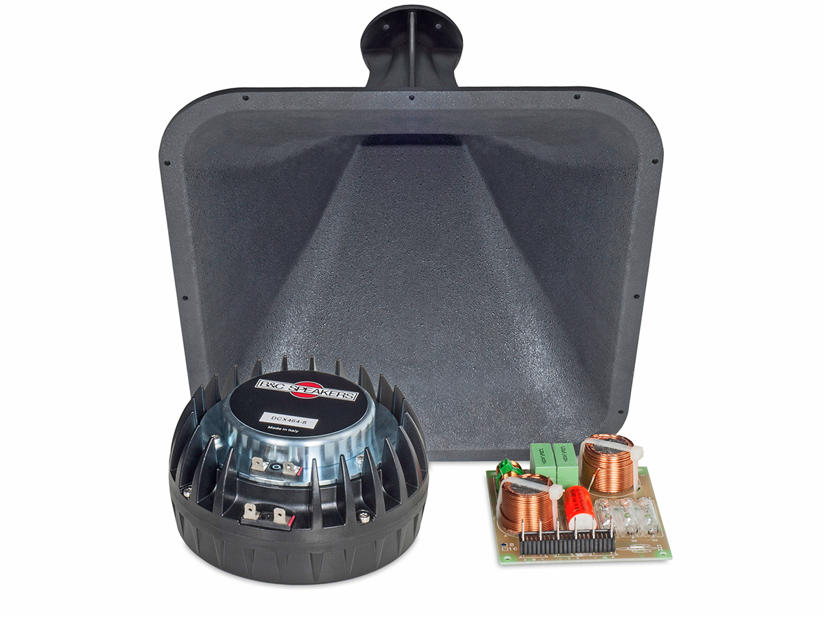
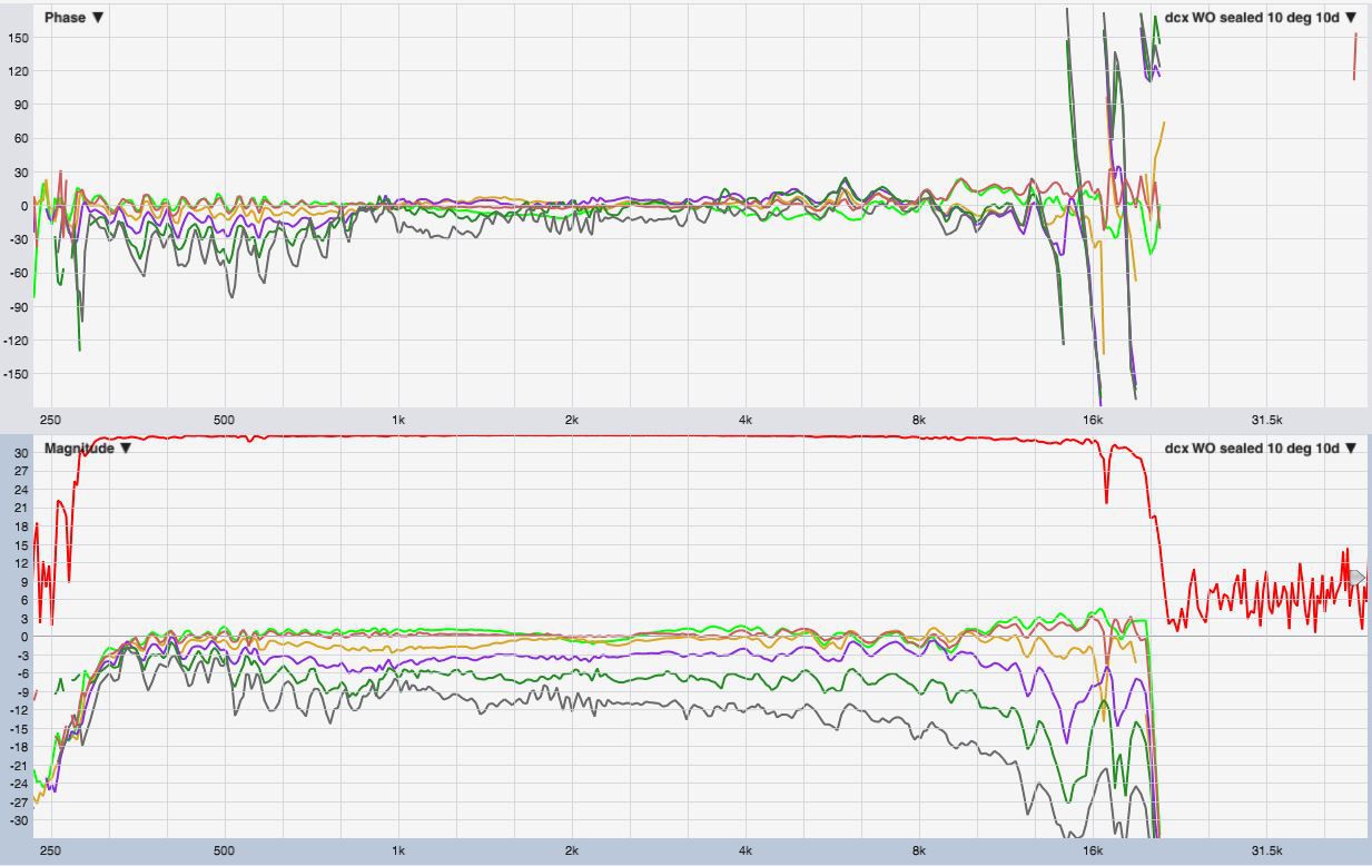
Anyway, below are some outdoor measurements of the B&C dcx464 CD on it. Supposedly B&C made the horn mainly to prove the dcx464 could actually pull 300Hz.
So I high passed at 300Hz, processed response to flat mag and phase at 10 deg off axis....and measured polars..... Looks like it can!
10 deg increments. Red is 10 deg, green is OA.
Raw and smoothed. The only other CD I have is a bms 4594he. I needed to high pass it at 400, may 370Hz lowest. It was very similar to the dcx464, other than smoother above 10k.
-
Hi VDS,
I've kinda let speaker processing become as much of a hobby as speaker building.
And have used a number of different platforms from simple analog crossovers, to much of the miniDSP stuff, to fixed prosound platforms like the Xilica XP & XD, to open architecture platforms like the Xilica Neutrino. Don't claim to be an expert at all, just saying I've been able to compare a number of alternatives.
My 2c advice for starting out with active, is that initially leaning is worth far more than the "right" equipment. So I always recommend starting with something inexpensive like the $200 miniDSP 2x4HD. It's quite decent, other than limited in channel count and processing capability.
When you outgrow it (as you most likely will
), you'll better know what you want and why....without feeling locked into a more substantial purchase, that may or may not have fully filled your needs and wants.
Good luck whatever way you go !
-
1
-
-
21 minutes ago, Edgar said:
@gnarly I sent you a PM.
3 hours ago, Edgar said:Be careful with this. If you arbitrarily place the response peak at the beginning, on some filters you will find that the resulting magnitude response is not what you expected.
Not necessarily. For example, the phase response of a Bessel lowpass filter is nearly linear within the passband, and the linearity improves with higher orders. (The same is not true, unfortunately, for Bessel highpass filters.)
It's strongly dependent upon the Q of the filters. Ultimately the phase change is, as you said, 90° per order. The slope at the critical frequency changes with Q.
Thank you for that !
I knew you had forgotten more about Bessel than I've ever seen 😁
-
1
-
-
2 hours ago, Edgar said:
Be careful with this. If you arbitrarily place the response peak at the beginning, on some filters you will find that the resulting magnitude response is not what you expected.
Is this perhaps when using wav as the FIR file? I have seen some strange results then.
So far, with csv files I've been able to put impulse peak anywhere without issue.
But that said, I haven't played with mixed-phase FIR all that much. I've been more interested in just achieving a higher tap count.
QuoteNot necessarily. For example, the phase response of a Bessel lowpass filter is nearly linear within the passband, and the linearity improves with higher orders. (The same is not true, unfortunately, for Bessel highpass filters.)
Bessels are certainly not my forte. Bewildering number of highpass options. And the term "order" doesn't seems to apply to them like BW or LRs.
I've seen on lowpass, that what my processor calls 'natural cutoff', group delay is indeed flat, but doubles for each order doubling.
Whereas for lowpass called '-3dB cutoff', group delay is flat but doesn't vary too much as "order" is increased.
And then Bessel highpass has 4 different types of settings....Yikes! beyond me.... I'll bet you have forgotten more about Bessel than I've learned 😅
But i really only look at Bessel, or any other non-complementary IIR out of curiosity.
As again, so far i've found complementary steep linear phase xovers to be a simple path with excellent results. (whenever latency can be tolerated)
QuoteIt's strongly dependent upon the Q of the filters. Ultimately the phase change is, as you said, 90° per order. The slope at the critical frequency changes with Q.
Yep.
I guess i see Q, order, group delay, phase wrap, etc..... as all just different ways of talking about the underlying issue.... non linear relative phase.
-
1 hour ago, Edgar said:
Fundamentally, you cannot achieve "zero degrees flat" in a causal system. I'm assuming that you are measuring 0° because you are mathematically removing the delay from the system. That's OK; I just want to emphasize that there is no difference between "linear phase with slope" and "zero phase", once you account for the delay mathematically.
It also demonstrates why a low-frequency FIR filter must have a lot of taps.
As the peak in the response gets closer to the start, the filter becomes closer to minimum phase. Minimum phase may not put the peak right at the start, but it will put it as close to the start as possible for a given causal magnitude response. The minimum phase system thus also exhibits minimum group delay for that magnitude response. In a minimum phase system, the phase response is related to the amplitude response through through the natural logarithm. https://en.wikipedia.org/wiki/Minimum_phase#Minimum_phase_as_minimum_group_delay
Yes, that's what I meant. And I believe out brain removes delay the same way out measurement programs do mathematically.
And more yes, that 'linear phase with slope' (on a linear frequency scale) is the same as 'zero phase'.
And another yes, regarding lots of taps needed for low freq.....my motto has become 'it takes time to fix time' ! 😄
I've been able to put impulse peaks right at the start of FIR filters for no delay. But it seems IIR is the better way to go, because it doesn't have the frequency resolution per number of taps issue mentioned earlier.
Going further back in our conversation, in response to your question what do I mean by 'phase wrapped signal'....
i meant wraps such as provided by IIR xovers, at 90 degrees per order.
I think they do concern the linearity of phase, because once beyond first order they guarantee that phase cannot be linear, and that the higher the order the greater the non-linearity.
When i measure IIR group delay as a function of frequency, holding order constant, i see that group delay approximately doubles for each octave decrease.
When i measure group delay as a function of order, holding frequency constant, I see it increases approx 2.5X for each order doubling.
So to me, since group delay is both frequency and order dependent, it simply reflects the degree of phase wrap, and where in frequency the wrap(s) occurred.


 My woofer ports take after Danley's Synergy and Unity horns, both in their placement and their size.

Nearly Full-Range Multiple Entry Horns (MEHs)
in Technical/Restorations
Posted · Edited by gnarly
Thanks for posting this description and the picts 😀
So on this new build you are working on, with all 4 sides equal, I gather you are planning on the same H vs V, correct?
If so what degree angle pattern ?
I think I might be able to pull off a flared square pattern with the bendy board; 60x60 etc. It's the different angles that melt my mellon, 90x60 etc.
The picture frame style has worked well for me, although i've tried to make the secondary flares removable, and it's been harder than expected to keep the joints from resonating when driven hard.
I very much share parlophone1's questions.
Extremely curious how you compare your DIY's to the K-402's, and your motivations behind the DIYs.
Thx again.
mark
edit:
ps....i now see you posted to parlophone1..