


gslettum
-
Posts
19 -
Joined
-
Last visited
Content Type
Forums
Events
Gallery
Posts posted by gslettum
-
-
On 5/6/2022 at 8:54 PM, dudaindc said:
I have two (2) RW10-D plate amps that are driving me nuts... without the schematics, I am basically stuck.
For both amps, all caps have been replaced with high-quality ones and not a trace of the yellow glue.The first one works fine (i.e., responds to all commands and I get sound) but just the display does not light up. Already changed the display, cable, etc., but nothing seems to solve the issue. Measuring the voltages in the flat cable pins I found that these do not match what I measured on other similar amps... it seems that logic/polarity is reversed for most pins.
The second one also works fine but I need to push the volume all the way up - it seems that the gain structure is wrong (e.g., one op-amp may not be working as it should).I thought it could be the digital volume chip but that is not easy to solder (at least for me) and I want to explore other possible causes for the issue.
Any thoughts or suggestions?
Thanks in advance!
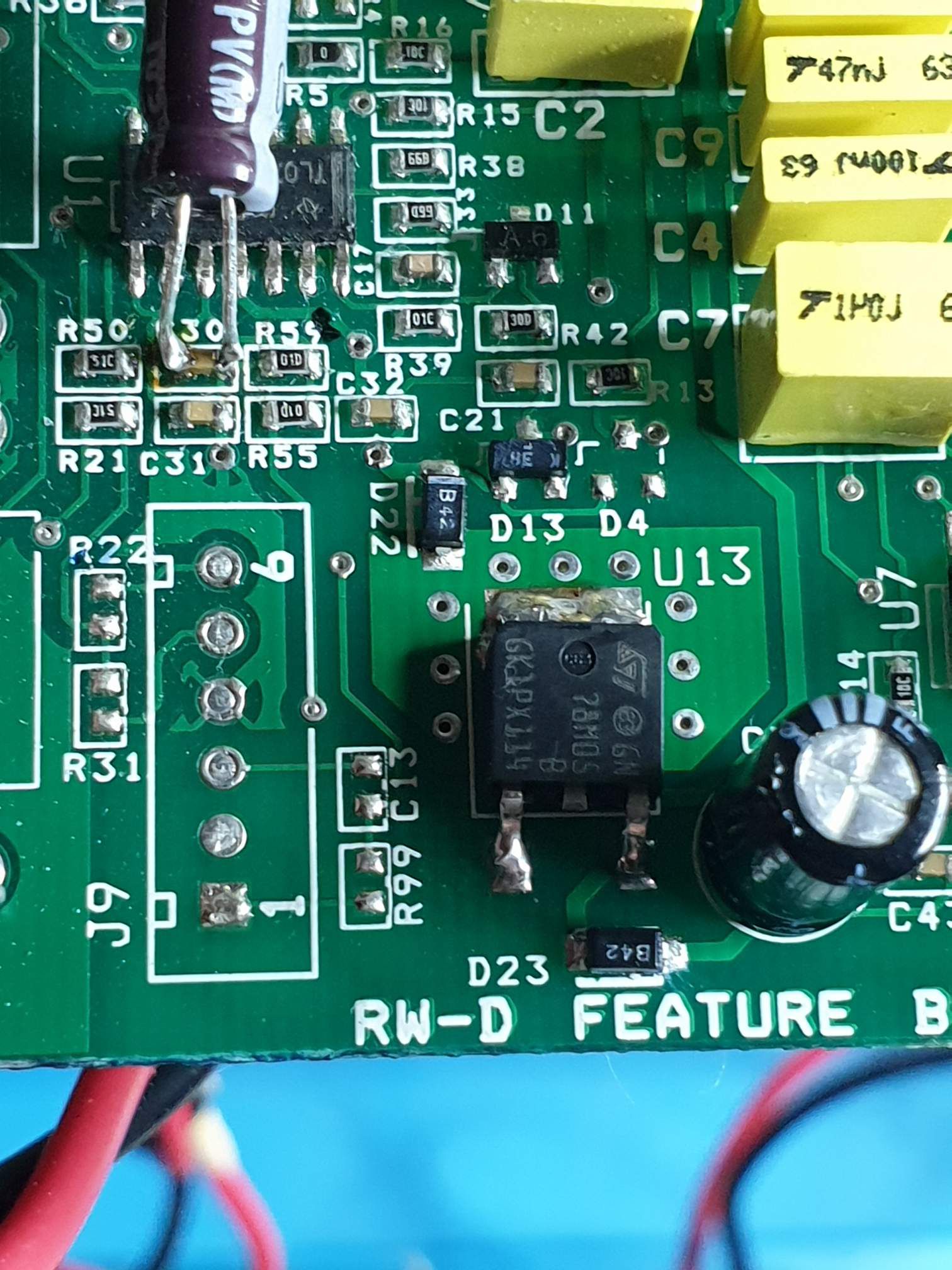
Check the 7805 regulator, U13. I had all the correct voltages. Still no display, just flashes when i turned the sub off.
-
Found at last the fault. 7805 V regulator in pre board was putting out only 1,5 V. New regulator and the display come alive and the rest followed😁

-
Hello
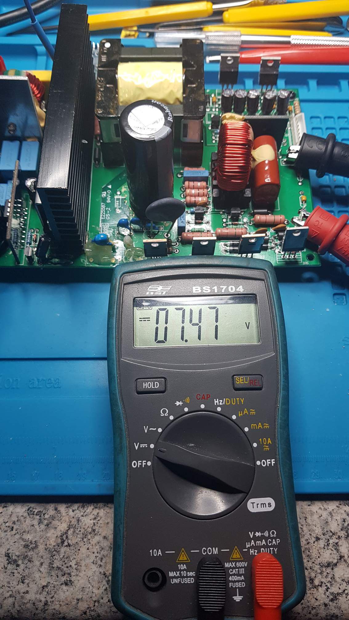
I have a klipsch rw10d with no sound or light om the display. I have changed the db6 diac and the mosfet. And now the Powerboard has 08.1 V output. I put the plateamp together. I have changed all the caps om outputboard and inputboard.
Still no light om the displayet or signal on the scoope from the outputboard.
Any idea off what else can be wrong? Bashboard maybe?
-
Getting there
-
 1
1
-
-
1 hour ago, ngen33r said:
Bash board is the next step once the primary side is stable. Might as well recap the whole board too. Never know whats under them until you pull them.I have recaped the whole secondary side of the board all ready, small caps too the big one. So next on the agenda is the bash. Not sure what kind of UC3842 i can order.
-
3 hours ago, ngen33r said:
It's never the caps!
Changed then anyway, for smd soldertraining😁. And all the diodes. I got power too the secondary side now, but have unstable 13-15 unstable volt at the CD+ and -. And the Q4 2sn4401 made some noise, and broke down.
Any idea? Bashboard?
-
1
-
-
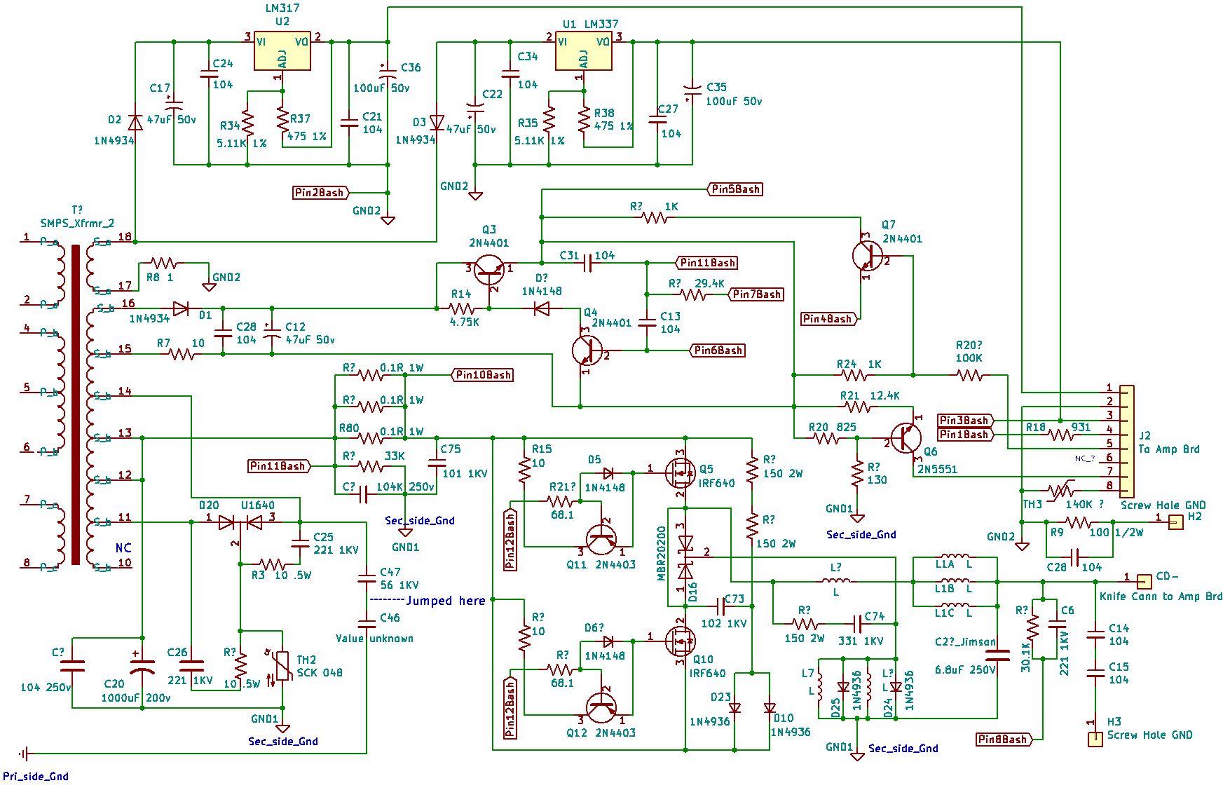
4 hours ago, ngen33r said:
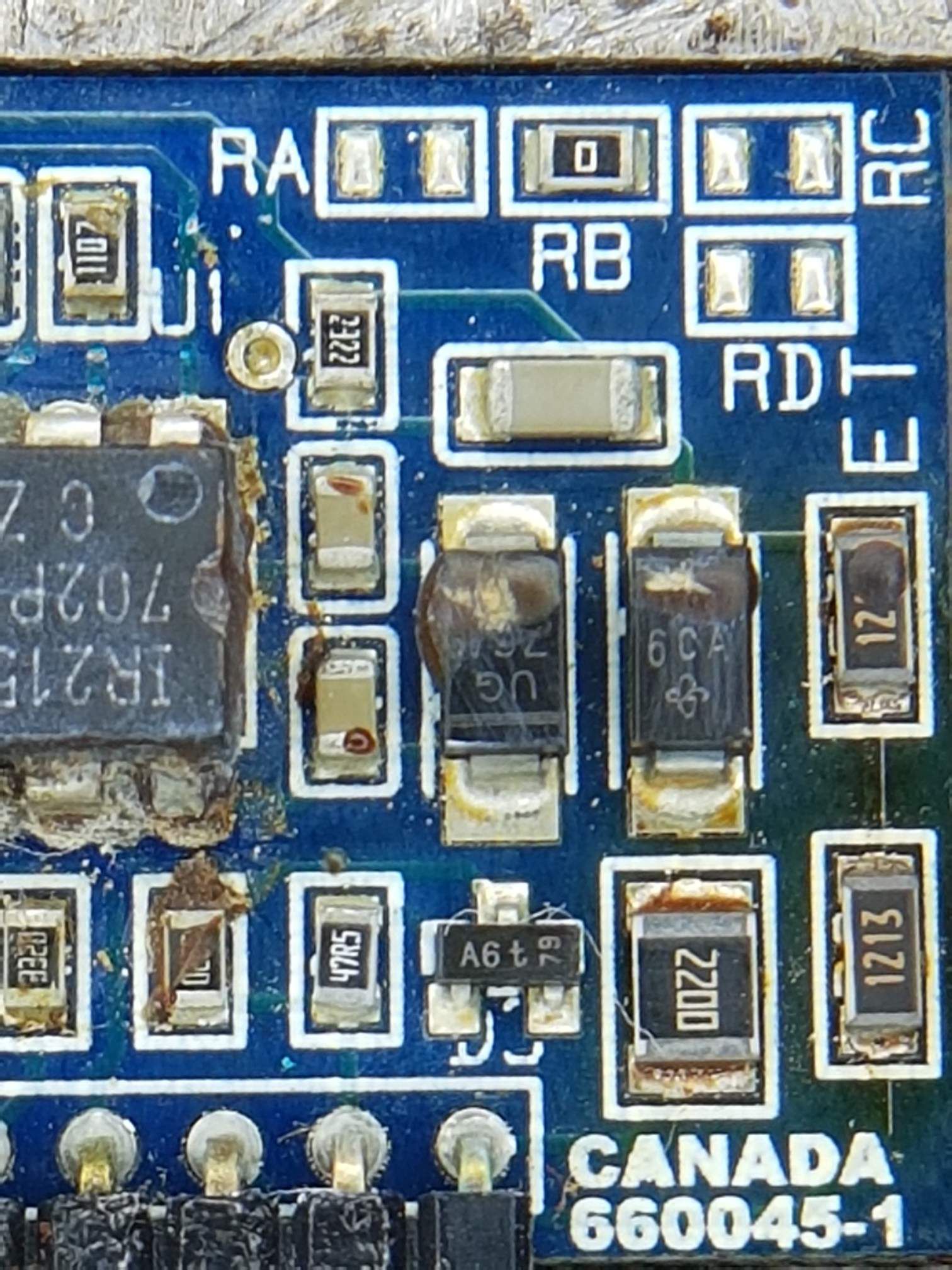
Here is what I have. It is not complete or updated. VERSION IS UNKNOWN DO NOT ASSUME RB. Looks like C6 needs to be able to handle 200V. Double check this.
Thanks.
So many different subwoofer brands used this amp, and now schematics around. Good kept secret, more secret then some gouverment documents😁
-
51 minutes ago, ngen33r said:
Look up the data sheet for the IC. I believe 50V will work for those. The ceramic caps are almost never bad. Usually just a diode and / or the IC.
I have changed the IC and the bas16 D3. Still nothing. So for the fun of it and usefully experience, i will rebuild the board. Have all the parts on hand, except the cap's and resistors.
I will check the datasheet for the IC.
-
Nobody knows the vdc on theese small caps. I can't get power too the secondary side. I think i have too rebuild the whole board. Everything else on the primary side is changed.
-
17 hours ago, ngen33r said:
The large mains? 200V 1000uFTheese small smd caps.
-
On 3/30/2021 at 8:42 PM, ngen33r said:
I will check if I have one tonight.
Any idea what the dc are on theese caps?
Glenn
-
Work in progress. I don't have fully working power supply, so take some time for a beginner like me. This belongs to a svs pc13 ultra, Bash 750w amp. Same supply as my polk dsw3000 micropro sub. Only difference is the inrushboard.
-
Anyone knows the vdc on the capacitors on the pwr board 660541-01?
-
On 3/25/2021 at 5:58 AM, Mike Gans said:
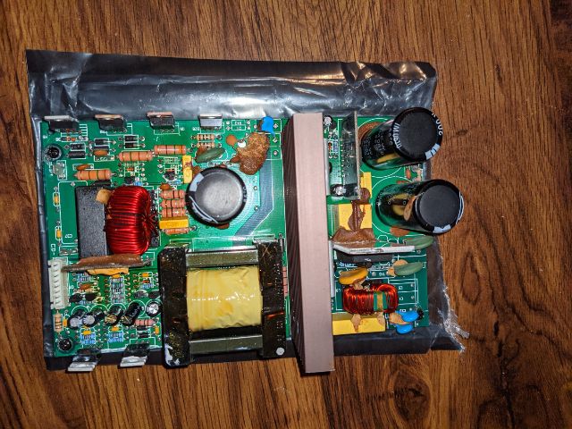
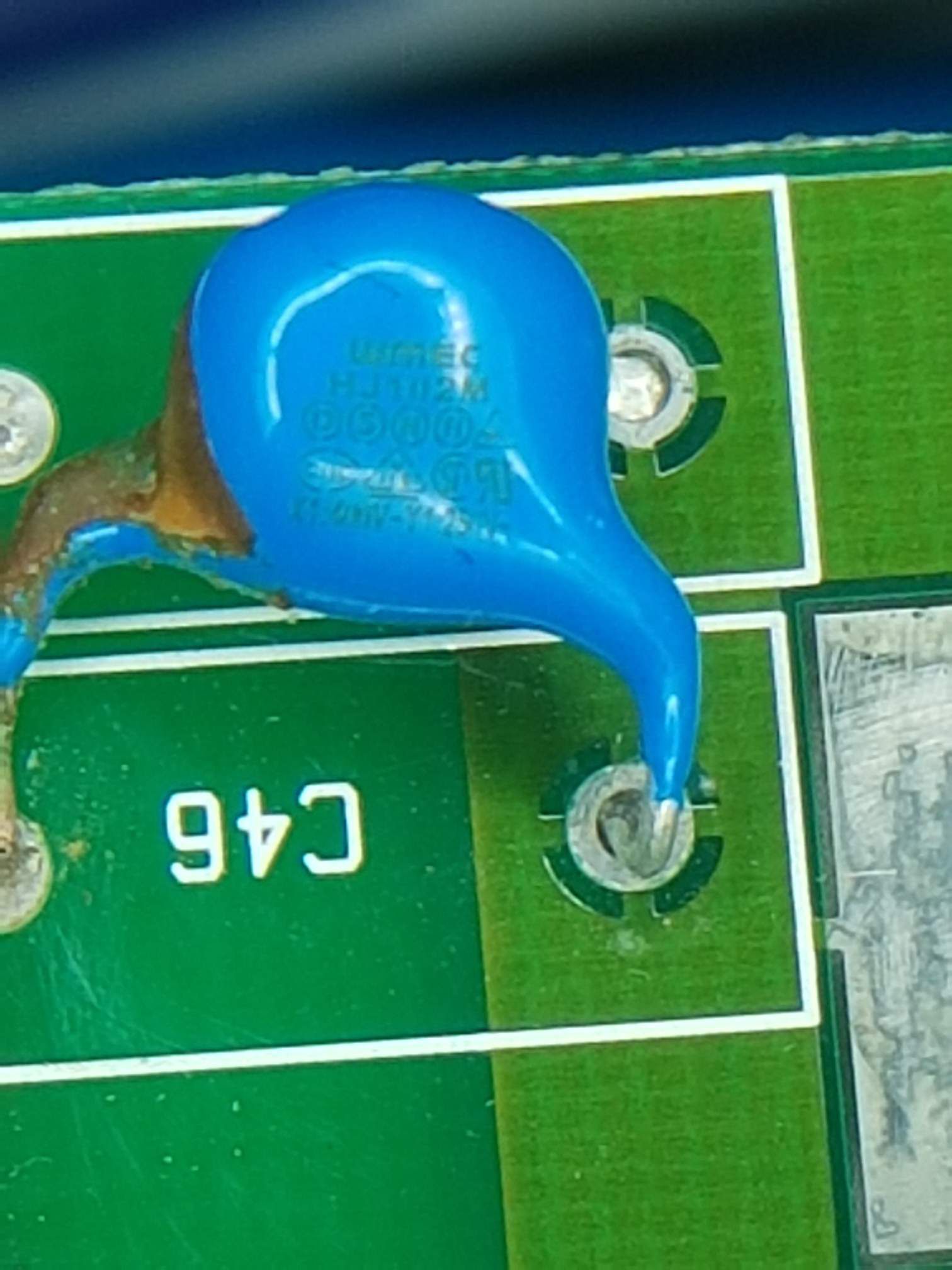
Sorry, I just attached a photo of the entire board and a close-up of the two caps soldered together.
I can't read what the blue caps are and not sure where I can get them from yet.
Looks like a lot of fun just to get rid of the browned glue.
Thank you!
Mike Gans
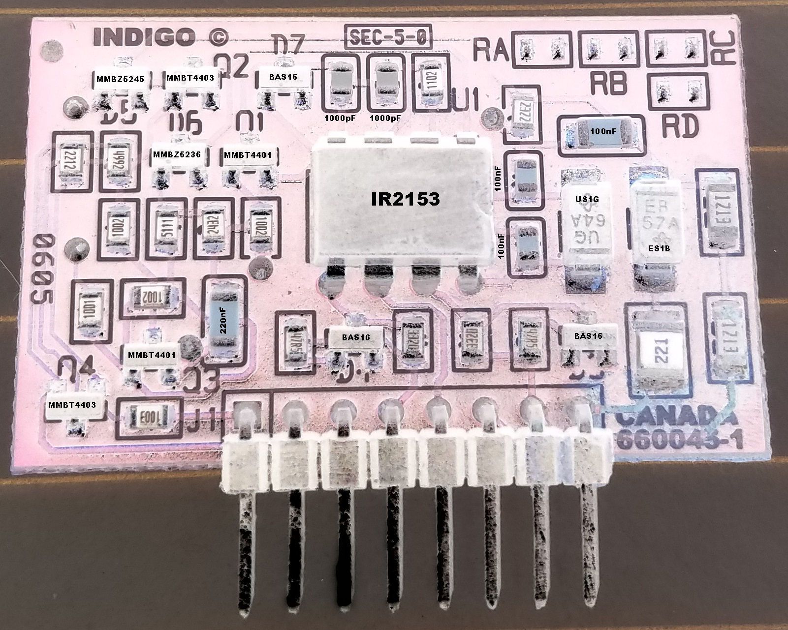
This is from my indigo 640047, rev 3 board.
Glenn
-
12 hours ago, Journey said:
Hi Gslettum ... On my PS the Bridge part number is shown in my latest schematic posting ... It is a KBU8G bridge.
I'm guessin it's at least 600V and some beefy amps ... at least 6A ... anything above this will do 8A 10A should be just fine as long as the footprint fits.
Here's the datasheet for it ...
https://pdf1.alldatasheet.com/datasheet-pdf/view/62072/GE/KBU8G.htmlGreat, thank you.
Very nice work on re-enginering👍. Way beyond my knowledge😁
-
32 minutes ago, ngen33r said:
Definitely more dedicated to this than I was. But now I have a solid reference for future videos!!!!!
This might help with some of the pin labels. Not sure if they are the same so please verify.Your videos sure help a befinner like me. I will make a current limiter and order a de-solder vacuumstation. But first i have to find out what kind of rectifier it is. Have been told that it is a generic 600v, 6A kind?
-
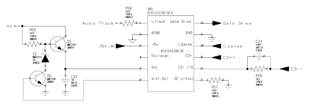
On 7.2.2021 at 3:25 PM, Journey said:
Hi There again ... well I'm back ...
I finally finished up the schematic for the secondary side of the PS.
Obviously I cannot gaurantee 100% accuracy but I'm confident it's like 99.8% close and as you will see many Component reference numbers are missing
due to being hidden ... didn't fell like desoldering so many parts to get at them. Some part numbers are also obviously unavailable.
One can deduce where the part is on the brd by just navigating the schematic and making comparitive observations.
Anyone out there ... feel free to point out any errors and let me know so I can make those corrections ... I spent many many hours doing this and triple checking and more as I built it up.
I forgot to ask you Wayne if you did up a schematic for the BASH brd ? If so could you send it so I can rework if nessecary to include it on this schematic.
One other thing I forgot to do is make a note on the page about the 2 isolated GND's .... GND1 is marked as the main secondary side ground and GND2 is for the regulator section mostly and the Bash Brd ... so they are somehow isolated ... not sure how yet but the two are distinctly separate.
Wow... Nice work
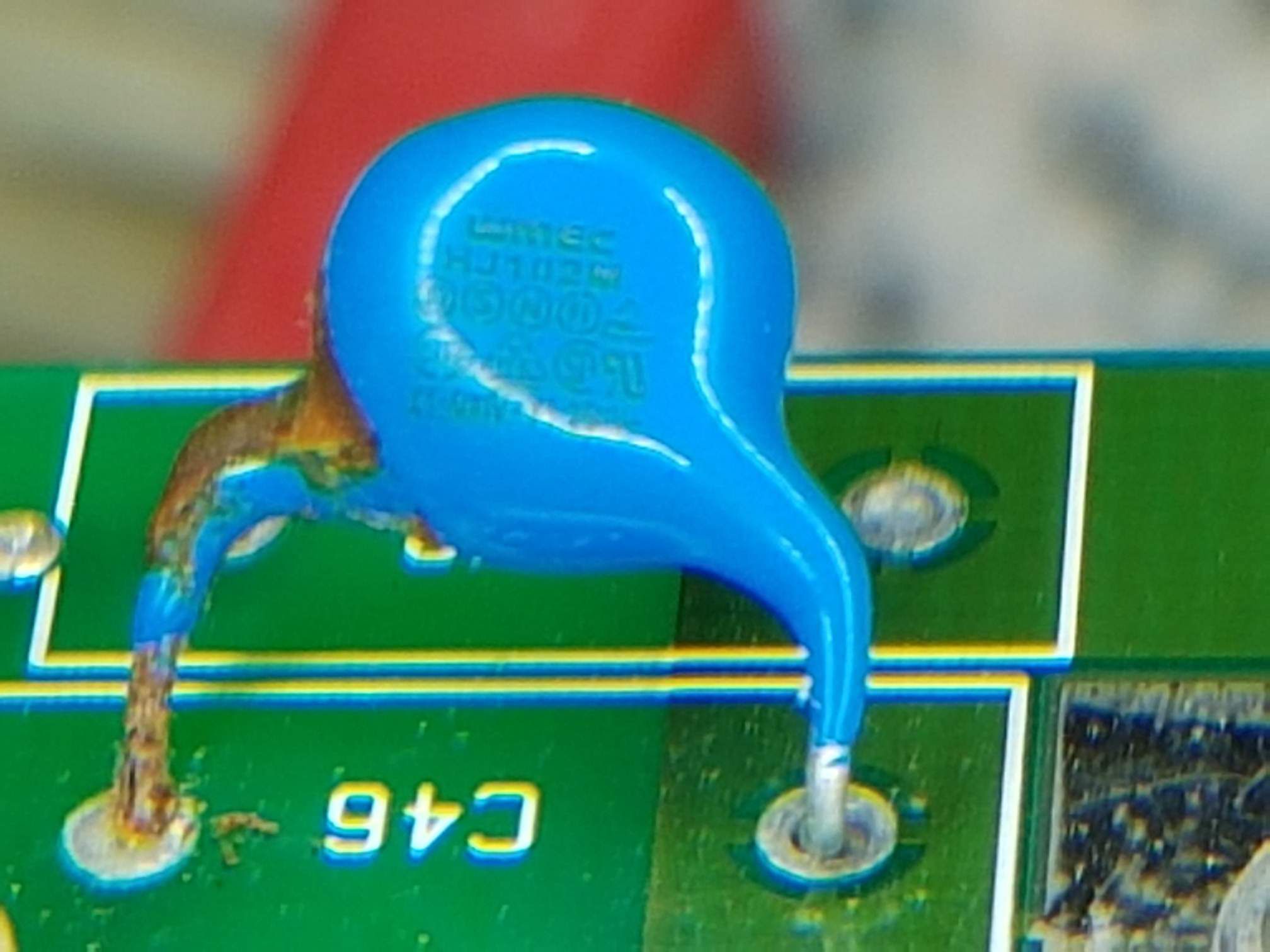
C46 on my rev 3 board is a hj102m
-
Hallo
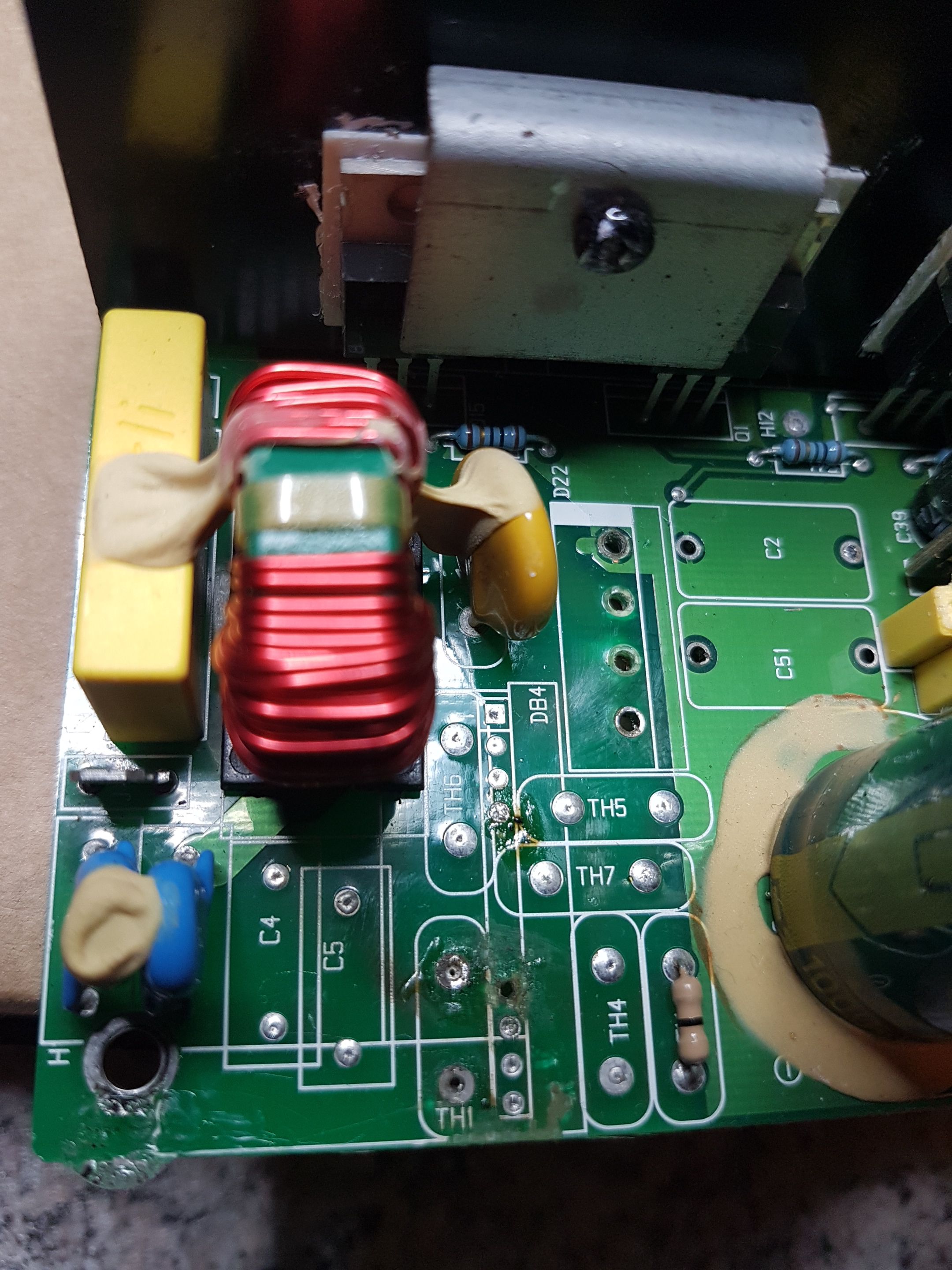
As you can see, i'm missing some parts on this indigo 640047, rev:3 board. Two thermistors, 2 caps and the rectifier. Found the caps and thermistors from this site👍.
Anyone knows type and value on the rectifier?
Great videos from ngen33r. Gives me hope too fix this powersupply.
This board belongs too polk dsw3000 micropro by the way.
Glenn
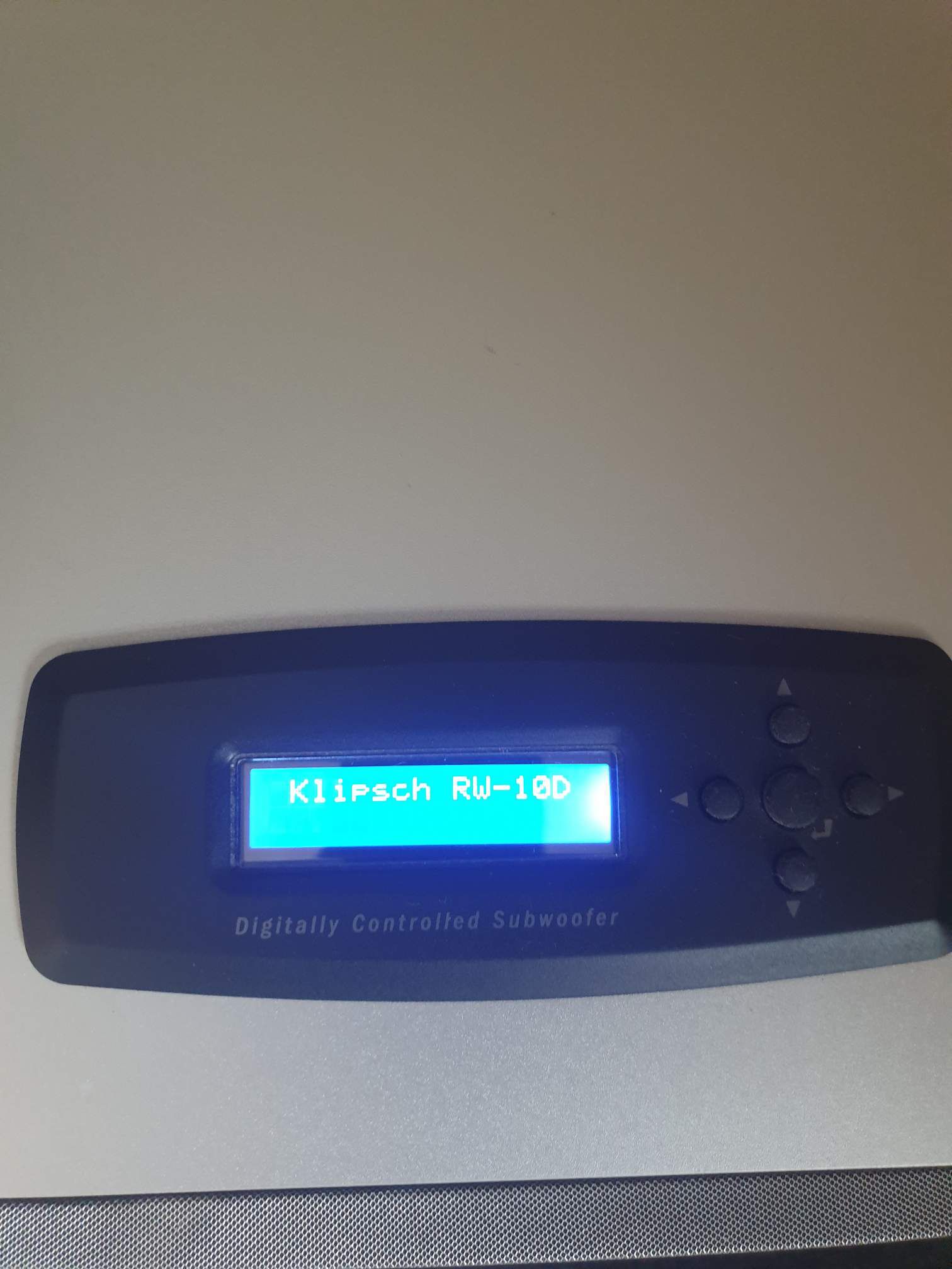
RW-10 - RW-10D / RW-12 - RW-12D REPAIR BLOG
in Technical/Restorations
Posted
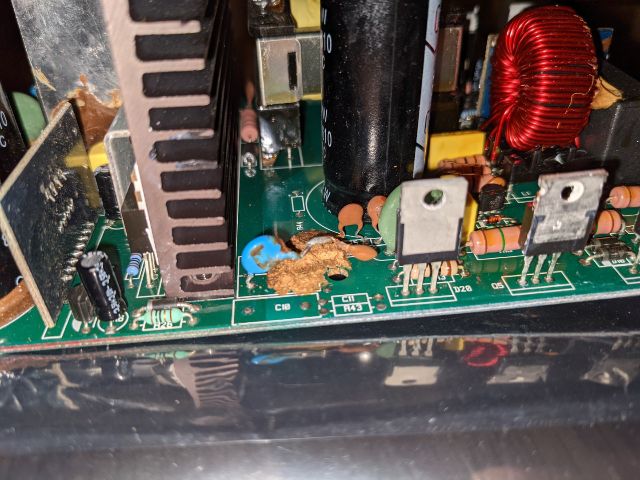
The Brown glue most come off all over the amp.
You have a pwr board next to two main capacitators?
This can also be faulty, and mayby two mosfet transistores. Located next to the main transformer.
On the pwr board you have a Black og blue db6 diac. This has been broken on a few amp's that i have worked on, an the mosfet on the primary side.
This pcb board can be tricky to work on if you don't have a good soldersucker. Best to use vacuumtype. The eylets breaks easy and it's two layer board.