

Dylanl
-
Posts
1725 -
Joined
-
Last visited
Content Type
Forums
Events
Gallery
Posts posted by Dylanl
-
-
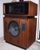
Is this what you mean

-
I have other pictures if you need them. I am having real difficulty uploading my files to this site. Sorry. Email me at Artvandelay1@peoplepc.com and I will forward them to you if you would like.
-
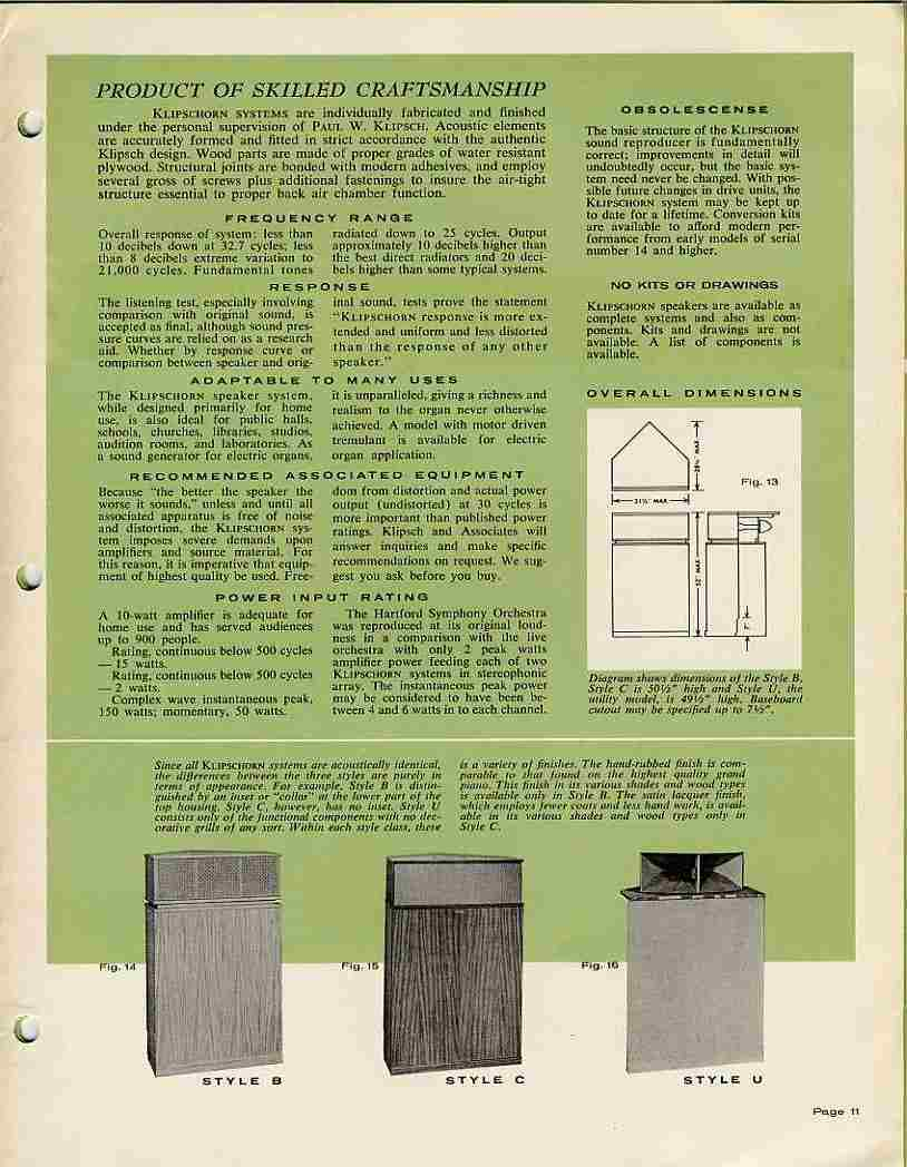
I have a pair of 1974 C version Khorns and the upper section is set back 1" to the grill cloth. I was thinking about making the B mod on my K-horns but I now enjoy the look of the C. One thing to think about is the extra inch seems to raise the sound from the 2 horns above your head. Not much but something to think about. I also think the value is somewhat changed once you alter the original. Let me know how you do with your changes.
-
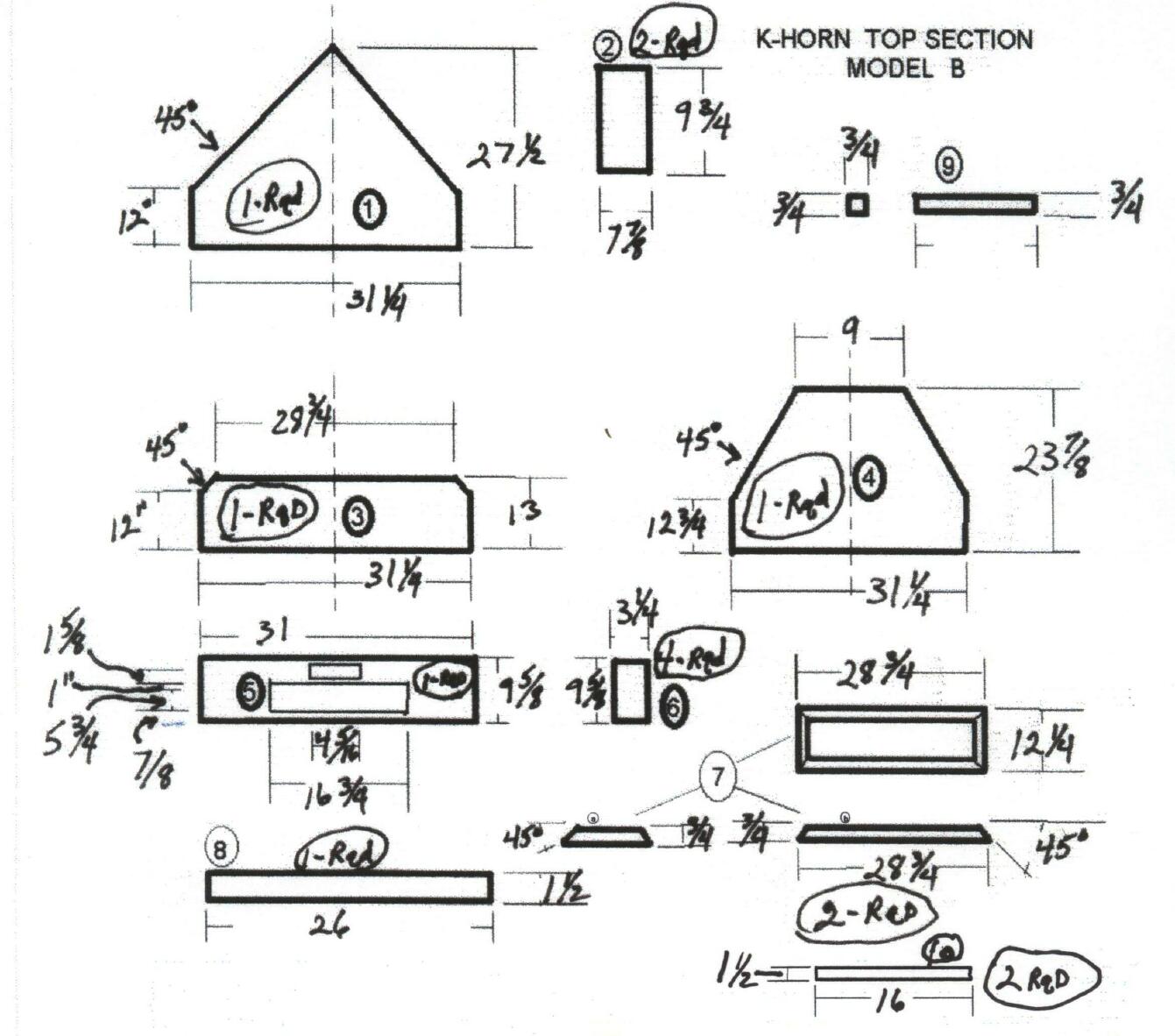
Khorn Top Section Model B
All exposed edges should be edge banded before assembly. I like to cut the pieces as I go. This will allow for any adjustments. Top section assembled out of 3/4 plywood. A few pictures of model b and c are included to assist in assembly. None of the drawings included are to scale.
Sub-assembly 1 -Assemble parts 7a (2 required) and 7b (2 required) to make part 7 and this completes the first sub-assembly. You may want to add glue block in each corner for added stability.
Sub-assembly 2 -On part 3(1 required),from the bottom drill and countersink 4 holes to except sub assembly 3,approx. 1 3/8 inches in from the outside edge.and 7 and 12 inches back from the front edge. Place a 1/4 inch bolt in each hole from the bottom side( use a small amount of epoxy around the shank just under the head of the bolt to hold it in place).
On part 4(1 required) place part 7 as far back as it will go without any overhang and equal distants from the outside edges(see fig 5). Mark the inside with witness marks. Predrill and countersink 10 holes through part 7 top to bottom(through the ply). place glue on bottom side of part 7 and attach to part4 with screws(making sure witness marks are aligned).Place part 3 on top of part7 and align with the back of part 7 and the sides of part 4(see fig.5). Place witness marks on the underside of part3 by tracing around the where part 7 and part3 come together. Drill 10 holes thru the bottom side of part3 about 3/8 inch to the inside of the witness marks and along the backside. Countersink all these holes from the topside of part3. Apply glue to the bottom side of part3 along the inside of witness marks. Realign part3 and attach with screws. This completes sub-assembly 2.
Sub-assembly 3 -On the inside of one part2, align one part 9(7inches long) along the top,butt end flush to back side of part2(glue and screw). do the same at the bottom. Align another part9(8 1/2 inches long) along the front, opposite of top and bottom. Holes need to be drilled in the bottom part9 to be attached to part3. Align to part3 and allow for a 1/16 inch shadow line on part3. Mark and drill holes. Do a mirror image assembly for the second part 2.(see fig.1)
On the underside of part1, align one part2(upright and side brace part9- 8 1/2 inch- facing forward) along the 12 inch portion leaving a 1/16 inch reveal or shadow line (see fig.3 top right)( make sure the holes to attach part3 are facing up). Move it back as far as it will go with no overhang.(see fig.1) Do a mirror image assembly on the opposite 12 inch portion. Part8 should be turned upright on it's edge, glued and screwed 4 inches from the front edge and centered from edge to edge(see fig.1and2). Parts10 should be placed face down in a V-formation 3 inches from the angle edges and 6 3/4 inches from the point (see fig.2and3). Glue and screw in place. At this point, it is a good to round over the point just a little to prevent it from causing damage to your corners.
Flip part1 assembly over and align the holes to the mounting bolts on part 3. Install nuts and tighten.(No glue). Measure between Parts1 and 4. Cut two pieces(approx. 11 5/8 for model b or 9 7/8 for model c) that length and 1 1/2 inches wide and two glue block about 2 inches long. Attach one end of the 11 5/8 inch piece to part9 with screw. Then align glue block with the bottom of the 11 5/8 piece. glue and screw block down to part 4. then attach the 11 5/8 piece to block with screw.(see fig.2and5)
Sub-assembly 4 -Glue and align two part6's face to face and use a few scerws to keep them together.Do the other two. On the back side of part5 glue,align Part6. Screw into part6 assemblies thru the front of part5. Cut out the driver holes and paint this assembly flat black. then cover with grill cloth. Install tweeter and mid-range horn lense
At this point you should drill two holes thru the forward facing part9- 8 1/2 inch piece (see fig.1). These holes will allow you to mount parts 5 and 6 from inside the overall assembly.. Support the horn lense with a metal strap once installed. Install the mid-range driver.
Mounting the top section to the bass bin is easy. You will need two L-shaped brackets, two bolts with wood threads on one end and nut type threads on the otherand two wing nuts. On the side of the bass bin measure back about 12 inches from the front and down about 3/8 inch from the top. Screw in the L-bracket so the top of the bracket is down the measured 3/8 inch. Align the top section on top of the bass bin. With a nail or an awl, mark into the bottom of the top section thru one of the holes in the L-bracket. Remove top section and drill pilot holes on each side. screw in the bolts with the wood thread ends going into the top section. Realign top section on top of the bass bin with the other ends of the bolts going thru the holes in the L-brackets. Tighten the two sections together with wing nuts.
Model C top section can be achieved by eliminating part 3 and 7. Attaching sub-assembly 3 directly to part 4. All other measurements and proceedures remain the same.
These instructions are based on my assembly experience with this project. Others may vary.
Sorry about that.I overlooked that one inch height measurement on part 7. I gave the length and thickness but no height. It is one inch.
Congrats on the amp. Gonna be a sweet set-up. I'm jealous. Now you'll have to shell out a few more bucks for a high end cd player, interconnects,etc.,etc.,etc. It never stops. Boy, you are hooked now....LOL!
Brett,
Yes, the riser is 1" tall.
I'm sure the 299 will work well with your speakers.
My speakers are KBRL.
The trim piece is 1/2"thick x 2"tall, bigger than I thought!
The riser piece is 1" tall. I think I know where you are referring to when
you say:
"From pictures it looks like the bottom plate on the upper horn only
goes back to where it meets the wall".
-
Here is a picture with measurements
-
I have a Marantz MM9000 5 x 150 and it makes a big difference. More than any HT receiver could. With a good amp you will literally feel the difference
-
D-MAN you should feel my wall shake even at moderate levels. That is why my thinking is heading toward re-enforcement. I know it was mentioned somewhere before, but there is a good book that Artto was pimpimg on room acoustics. Does anyone know the name of it and where I can buy it?
-
Anyone there?
-
So are you saying this would be a good thing to do? It would not be that much work for me to do. I also feel like the floor to my upstairs rooms are moving from the bass in the game room where the horns are. You can not feel it downstairs as well as you can upstairs. Odd huh??
-
Has anyone ever beefed up the existing corners in a room to see if performance on Klipschorns would increase? The reason I ask is that my current walls (corners) actually vibrate from the bass coming out of my horns. This has to be a loss in the speakers output. My walls are on 16" centers 2x4 with 4" of insulation & 1/2" drywall. What if I removed the 1/2 drywall, braced the existing studs, added a few more studs out to 4'away from the corner & finally replaced the existing drywall with 1/4 MDF board and covered it with 1/4 drywall. Do you feel the bass would be better?
-
Just my 2 cents. I own both RF7's & Klipschorns. I have tested both with SS & Tube amps and there is no comparison in mid range between the two. I mean not even close. I would like to try the newer crossovers for the RF7's to see if this would bring things closer. Since my Klipschorn purchase the RF7's have become movie speakers. I agree with the other posters that stated that Klipsch must have built this speaker to a price point. That is why I purchased them. I still believe "great bang for the buck" in comparison to what is out there.
-
Has anyone posted or know the true Hz results from the Dope from Hope plans (Built Correctly) vs. standard house walls. I always wondered if there was any fall off in db? You would think if the false corners were built and packed with sand the results may be better seeing that standard construction in home built in the last 15 yrs. is drywall over 2 x 4 studs on 16" centers.
-
So is it safe to use Khorns at 4 ohms or not? If so what change would be heard in sound low end and top?
-
Fedex droped and bent my face plate while the amp was in transit. Does any one have or know where I could get a faceplate?
-
The best stuff that I ever used and still do is a product called NEVR-DULL. It is a cotton wadding with some sort of oil penetrated into the cotton. Cost $3.00 a can. You can find it at any local hardware store and polishes all metals. Try it you will like it
-
So, does every one agree that I would overheat the voice coil if I tried to solder to the woofer without a heat sink?
-
If I made this mod. would using female plugs create resistance in the signal? It would make the job so much eaiser. Many however have spoke about soldering directly to the speaker terminals. What do you guys think is the best way? I am going to try this mod (gauge upgrade)to the bass bin. Just need to know which way to proceed.
-
3dzapper, that is exactley why I keep thinking of doing it. Because of posts like yours. There is a site on the web that enables you to produce your own waves and burn them to CD. I was going to test this on the lower waves 40 down to 30 with stock wire and then make the mod and test agian. I think if what you are saying is correct the slam would translate into a slightly greater SPL in those frequencies. Does anyone have any other ideas as how this wire issue could be put to bed. (Sorry 1974)
-
What! No response?
-
I was thinking of making this mod. on my horns. Many say I will hear no change others say the opposite. I was wondering if there was anyone that did make this change and documented the difference with sine waves & a SPL meter? A before and after test would be good testimony to prove one mindset or the other. Doing all the work for an imagined upgrade is not my style of fun. Anyway thanks for the help
-
Dean, why not just build the false corners. That is what I am going to do. Instead of using the traditional plans if you have some plywood around mount it to the back of the horns and see what you get. My room is very similar and as other have said the bass is much stronger at some points in my room and less in others. I did see a huge improvement in bass sealing them to the corners.
-
Thanks all. When I get my amp back I am going to give it a try.
-
Dean I purchased my horns off of Bigdnfay from the forum. Once he built his own he had no space for the Model C 74 Khorns so he sold them to me. Best purchase I ever made other than my (mail order Russian Bride). I still have the RF7's also. Since I have a very good sub (SVS) I thought I would at least try. After having a few over to listen to my system, I found that the way I had my sub set for music was way overkill. That is why I was asking where on my horns the crossover would be set. Thanks all for the help, I knew there were many hiding in the closet. Why do so many feel that a sub is like voodoo? I think it is 2 channel stigma. No speaker that fits into your home can do it all. As near to perfection as the Khorn is they will always have their limitations. That's not even taking the room into consideration. Doesn't coming out feel good!
-
Just a thought. Wow! If it is so crazy of a thought why have some tried it? I would bet more than just a few have and maybe in the end decided against ( so be it ). Myself I have never tried so why not ask?


ALK or AA
in Technical/Restorations
Posted
I have a set of 74 Khorns with AA crossovers. Would there be any benefit to switching these out for ALK's. If so what are the sonic differences?