


D-MAN
-
Posts
4413 -
Joined
-
Last visited
Content Type
Forums
Events
Gallery
Posts posted by D-MAN
-
-
Think hard-surface reflectors, like mirrors, then. Above 300Hz. Below doesn't matter due to the wavelengths involved.
DM
-
The top-exhausting concept is entirely viable, and I think the benefits outweigh the drawbacks, for a corner horn.
It is an under-rated approach. But I intend to leave no stone unturned...
Here is my top-firing patent document, you won't see it for another 2 years! (So get your copy now, heh, heh)...
That's how long it takes to just PUBLISH (not issue) on the USPTO website.
DM
-
A very early example of a top-firing horn from 1934 (BK - before Khorn - heh!) from Ephaim.
DM
-
-
-
Here is Rice's second, smaller rear-loaded design of great simplicity. This uses a 12" driver and stands approx. 36 inches tall. It is a BOTTOM-exhausting horn, a related animal.
DM
-
No comments on the 3rd design, huh? The Top-firing one? Well, it IS pretty AVANT-GARDE!
NOT! - but there are some special advantages of top-firing, first of which, you can put anything you want right up against it, furniture, cabinets, etc., unlike the type of horns you might be used to. It is also a smaller footprint than anything of a comparable low frequency cutoff. Did I mention that it has a smaller footprint than a Khorn? By about 3 inches less intrusion into the room. But I digress...
Top-exhausting renders the requirements of side-wall space (other than a certain ceiling height) a moot point.
Here are some past example of top-exhausting bass horns...
First one of my favorite inventors, Warren A. Rice who did 3 different corner horn patents, two of which are top-firing designs. Here is the earliest of his designs in pdf format. It is a rear-loaded horn.
DM
-
No, do not add filler UNLESS you specifically are attempting to filter out the higher frequencies (and/or lower efficiency, etc.).
Filler (absorptive material) is an added viscosity (loss) and slows down the soundwaves, which tend to cancel by phase and losses due to viscosity.
Viscosity is the tendancy of air to "stick" to surfaces. Fibrous material has lots of surface(s) to stick to, slowing the waveform down, enough that phase cancellation can take effect, as well as losses (i.e., motion into heat) from viscous friction. The heat is minimal and is considered adiabatic, but it is still indicative of a loss of energy.
DM
-
If you have the room for an open baffle, then think about trying this...
This looks very promising...
DM
-
Airflow over the wings is what makes it fly, and with zero air speed over the wings, zero flight.
DM
Why do you assume there is "zero air speed"? What force is exerted by the conveyor on the plane to impede the plane's forward motion?
I have to go out for a while. So you have time to think.
Are you NUTS?! the jet engines exhausting one way and the conveyor going the opposite direction at exactly the same compensating speed? Try ZERO air speed...
To think otherwise is shockingly stupid, but I see you've already signed up for that one.
I'm going out for awhile so you have time to not be as ...
DM
-
An expansion chamber? I think that is a close analogy, although the outcome is somewhat different... an expansion chamber is highly capacitive, that is, it has some of the properties of a capacitor, such as "storing and discharging" acoustic energy based on frequency. An expansion chamber DOES alter the acoustic impedance, though, but that's as far as the analogy goes, seems to me...
For our purposes, a "rubber throat" is not the same as an expansion chamber because it expressly does NOT want to store and discharge ANY energy - rather, it wants to transmit it from one end to the other altering the impedance along the way from a relatively high impedance to somewhat lower at the section "mouth". The faster flare rate (one that expands rapidly) is less restrictive to start with, and therefore the impedance seen by the driver is less than if the throat ection was a lower (slower) expansion rate. That is it in a nutshell.
It also doesn't have anything to do with turbulence, either, in a horn.
Think acoustical resistance, i.e., putting the driver "under pressure" or giving it something to push against. The flare rates can be used to control the amount of pressure applied to the driver. Some drivers operate better under alot of pressure, and others not so much, although all tend to "like" some pressure, that is, a higher than atmospheric acoustical resistance to push against.
DM
-
Think "Acoustic Transformer"... that's technically what horns are, and multiple horns of differing flare rates connected together transform or transfer the acoustic impedance from the mouth of one section to the throat of another.
The "rubber throat" is typically (but not always, as in the case of the LS) a means to reduce (or increase as desired) the throat reactance seen by the driver by effectively transferring the acoustic impedance to the "next" flare section, using a rapid flare rate at the throat followed by a slower (lower) rate. So the driver "sees" a rapid flare rate and therefore a lower overall throat reactance, due to a rapid flare rate being "easier to push air through" than a lower flare rate which has a higher reactance.
Let me define the terms "impedance" and "reactance"... impedance is "the resistance to air movement", reactance is the property of air to "compress and rebound", if you will. In essence, reactance could be described as a time-delayed "pushing back" property. Reactance has some properties of "storing" energy to a degree, somewhat like a capacitance. Resistance, on the other hand, is the impeding component presented by an enclosed column of air to the movement of air being pushed thorugh in a single direction. The "tighter" or more restrictive the passage as with a slow (low Fc) flare rate, the higher the impedance and subsequent reactance.
Since horns are acoustic impedance TRANSFERING devices, (or acoustic TRANSFORMERS) it is a natural course of events that different horns of differing flare rates can be connected to achieve a desired acoustical impredance at the throat, each respective section's MOUTH being the subsequent section's THROAT impedance.
The original concept was put forth by H.F. Olson of RCA fame in the 40's, which PWK referenced in the original 1945 Khorn patent. The values of the acoustic impedance/reactance is calculated at the mouth of the horn and then is worked backwards towards the throat, a flare-rate section at a time. The use of acoustic impedance values can allow a horn design to present the desired impedance to virtually any driver. The "rubber throat" of higher Fc shows less acoustic impedance to the driver, for instance. A throat section of lower Fc would present more impedance and subsequent reactance to the driver.
One important issue is that the SUBSEQUENT flare rate, whether an intermediate or a terminal (MOUTH) section needs to be LOWER than the preceding section's flare rate.
The Khorn and Jubilee follow this pattern as throat=rapid, intermediate=low, terminal=between the previous values.
Interestingly, it is the terminal (mouth) section that determines the overall Fc of the horn, regardless of how many intermediate flare sections are used. It is NOT an average, etc.
The differing flare rates TYPICALLY allows for a wider bandwidth than a single flare rate horn.
This gets messy like in the case of the LS which uses a low flare rate at the throat, followed by a 125Hz Fc terminal section, the result being a nominal Fc for the horn of approx. 70Hz. The slower throat flare rate is used to provide the acoustic impedance best suited for the driver (the K33). A case of purposefully designing the throat reactance for a specific driver.
The Khorn uses 3 different flare rates, the LS/BELLE uses 2 but reversed from the typical setup, and the Jubilee uses 3.
DM
-
Airflow over the wings is what makes it fly, and with zero air speed over the wings, zero flight.
DM
-
Too small of a horn mouth is called "foreshortening", meaning that you have a flare rate for Fc (low frequency cutoff) "n" and an available mouth size for "y" which is a higher frequency.
The low frequency response will therefore suffer peaks and troughs due to reflections from the mouth.
Now, whether you can live with that is up to you.
Will you get bass out of it? Yes.
Will it be consistently flat across the bandwidth? No.
DM
-
Exactly! Ooops -
Wait - you guys let me get away with that?! A gallon is 231 cu. in.
A cubic foot is 1728 cu. in!
I need a memory upgrade.
DM
-
That'll come in handy; there's lots of musical stuff out there that goes that low!
NOT!
So I wonder, aside from the "novelty" value, what is the real [commercial] point?DM
-
I was thinking that this could be a candidate for an isobaric setup, too.
Probably require some "modifications" to get drivers to fit back-to-back, but it's certainly possible. JBL's would be an instant candidate, because of their relatively "thin" profile, I would think. The front panel would probably need some "mods" to make it happen.
Without cabinet changes per se, the removable motor boards can go, giving 3/4" extra clearance, and either an 1" extension frame added to the front panel or 1" extensions added to the driver "gasket" would work, seems to me. Also the front panel could overset the top/bottom, and the back chamber sides extended to add another inch or so. It's definitely do-able.
DM

-
Done!
Any others?
Bear in mind that these plans are as of yet "untested", and are for the full height dual-15" version only. The alternative version(s) plans are not yet finished.
Your part, in exchange, is to help me to correct any mistakes in the plans (if any, although I'm comfortable with them), and to take pics of the build progression (if possible), and certainly to make helpful suggestions, comments, etc, concerning the build, plans, etc.
I have no doubt that the completed enclosures will kick your tail in a decisive manner. That's what you get out of the deal. Seems like a fair exhange to me - I get free stuff to enhance the plans, and you get your rear-end kicked! What a great deal!!
DM
-
JC, no, the dual 15' plans are finished. Send me a "real" email so I can attach them.
Actually, the cutting plans are finished, but you are on your own for the rest of the "build", but since you did the Jubilee, you have got the general order down, so I don't think you'll need any further instructions!
Dana
-
The patents won't even publish for 18 months, so this all you're going to see for quite awhile!
DM
-
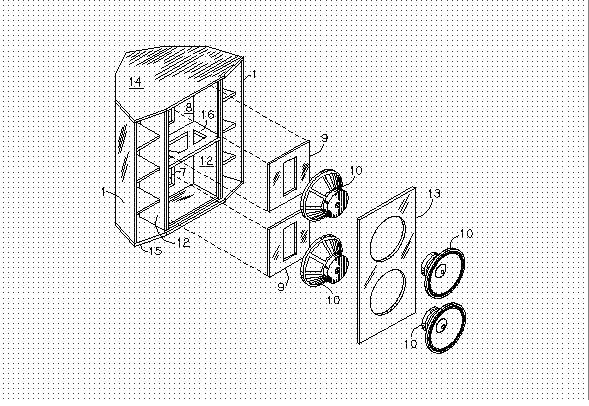
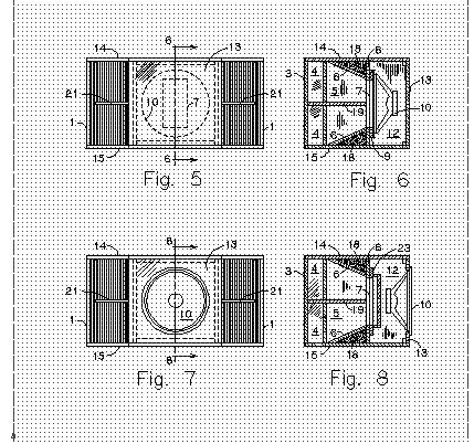
Same approx. footprint, etc. as the Jub, with couple of unique twists. Unitary throat with large throat area 154 sq. in. (combined), "adjustable" Vb, removable front panel allows different configurations. Increased versatility because you can swap drivers, etc., for extreme sensitivity or extreme power handling, depending on the application.
Single fold (benefit), large throat (benefit), overall pathlength is 5" shorter than Jub, but Jub has smaller throat area (that's basically a wash).
15" Drivers fall into 2 groups, large throat/large Vb, small(er) throat/small Vb. The large VB group is for the "standards", Bob's 15" drivers, K33E, CB15, Altec 515, JBL J-145, etc. Smaller Vb group Kappa Pro-15LF, etc. Driver sensitivity ranges from 96db to 99db ea., means minimum 2" mid generally required (high output). Naturally, I'm going with the BMS coax which is 113db-115db, which is an enabling factor in the design.
The Vb is selectively adjustable from 1.8 cu. ft per driver to a maximum of 3.2 feet per driver WITHOUT any fill in the rectangular back chamber, so if needed, more room can be had, however, I didn't find any drivers in my price range that would need more.
I included half-height versions for PA use (for portability). The 6x10" driver version is not in the drawings, but would basically follow the opposed-throat configurations seen in the 12" versions shown above.
JC, interested?
DM
-
And finally, the half-height versions of the twin 15's...
-
The "preferred" embodiment uses dual 15's.
-
Some possible alternative applications... opposed-throat configuration of 4x12" drivers shown.


Preparing for Jubilee build
in Technical/Restorations
Posted
Ha! Then WHY are there hard surface reflectors in the Jubilee?!
Yeah, I know... it depends on who you read...
DM