D-MAN
-
Posts
4413 -
Joined
-
Last visited
Content Type
Forums
Events
Gallery
Everything posted by D-MAN
-
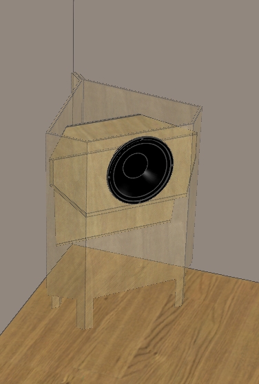
Duke, yeah, I've got my design finished, it just needs to be built. It is roughly around the size you suggest. Comes out approx. 41" tall x 25 w x 18 d with a single 15. I just want to share some of the thinking that went into it with others who might be interested. There is alot to think about. DM
-
Pretty complicated for what it does, of course, but the full-range crowd is pretty devoted to a different sort of audio if I may say so, i.e, these are NOT going to thump you. That isn't what they do. These are not going to be "rockers". Most of the designs are clearly geared towards extreme WAF rather than response, seems to me. Still very nice to look at regardless. I don't necessarily have a problem with that, but think "better than CW" means rocking when desired, which I don't think any of the Lowther-types can actually do. So I think somewhere between the large rear horns of the past and the small-signal types as seen above is an appropriate size to fit between the 40Hz corner horns and the "small-mouth bass" variety seen above. DM

-
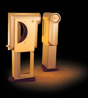
These are Lowther/Fostex, etc. full-range driver rear-loaders... There is a great deal of new horn design activity in this particular market niche.
-
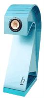
We have barely scratched the surface of the small-signal variety... Here is an example.
-
John, I wouldn't expect them to go any deeper, the horn flare rate is still the same regardless of the overall doubled mouth size. The LF cutoff is fixed regardless. Since the LS mouth size is already appropriate for the flare rate, doubling it has no effect on the frequency cutoff. The efficiency would effectively double, but that's it. DM
-
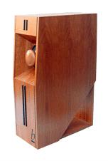
This unusual device is the Helffrich Catenary rear-loaded wall horn in what appears to be a push-pull (isobaric) LF driver configuration... This is a 1/4 space horn (wall), somewhat unusual, as is its expansion type. The picture is shown sideways. DM
-
A related rear-loaded application...
-
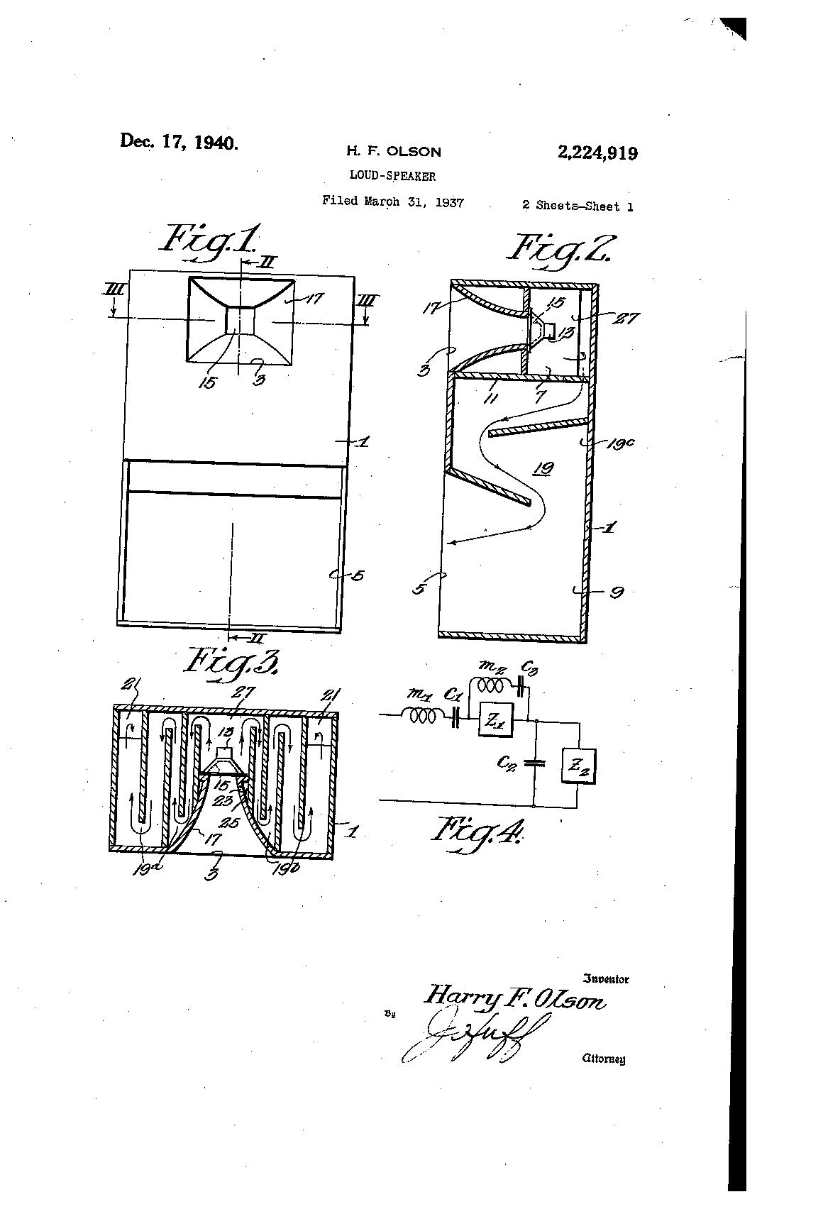
Do you have any pics or plans to post? As an aside, note in all of the above plans and such that there are no folding treatments employed; this is because you specifically don't want the high frequencies going through the horn. The tortuous folds are used as upper frequency limiters, the more the better. In particular, as seen in the Olsen patent, the use of extra capacitance and losses due to viscosity are purposely employed to limit the upper frequency band pass through the horn. Some employ a felt lining in the horn, as did the JBL Hartsfield in the rear-loaded embodiment (attached). DM
-
Duke, that's exactly what I said a ways back - the PUNCH of a cone-in-your-face combined with the LF efficiency of a bass horn! Bass players seem to love the scoops for exactly that reason - well that, and a reasonable SPL+performance-to-footprint ratio! But for domestic use, a scoop design of an appropriately low Fc is likely to be a bit large and will therefore most likely lack the appropriate WAF that a smaller enclosure MIGHT. I guess what I'm saying is that alot of very smart people spent their time designing rear-loaded horns instead of front-loaded designs, ranging from very complicated to the extremely simple, and there must be a reason beyond the historical time-and-place. Evidence points to the fact that the performance is better with a horn hanging off the back than a port, duct, or laborynth, etc. I understand the goal of enhanced horn-loading on the LF response in a smaller package than required for a front-loaded design. The trend towards smaller cabinetry has always been a driving force behind loudspeaker development, and the rear-loaded designs seem to dominate the horn portion of the market, both historically and presently. This is most likely due to the smaller footprint size. I tend to regard the footprint as being the all-important feature rather than the enclosure volume, due to the trend towards the "tall and skinny" direct radiators that abound in the present loudspeaker market. Nobody seems to care how tall they are, they are more concerned with the footprint, in particular with 1/2 or 1/4 space placement currently in vogue. I think that Klipsch-fans tend to ignore the rear-loaders as being some sort of a poor-step-child of the front-loaders, being that the Khorn has apparently outlived all of the large commercial DOMESTIC horn enclosures (with the notable exception being the Altec A7). I think we are needlessly dismissing a whole avenue of potentially good audio if we don't explore the rear-loaded bass horn designs too. Frankly, I have never heard one. Not even one! As far as summarily dismissing horn enclosures due to their large size, I'm already well beyond that consideration, having front-loaded corner horns. So I'm ready to explore the bare-faced cone side of things as long as there is a horn attached! One exciting ascpect is that the modern small-Vas driver available today open up some design possibilities not available in the past. A revisit of some of the better designs of the past seems to be in order... I'm excited about my new design because it is has a footprint of 18x25 - that's slightly larger than the CW. It's alot taller though, but I personally think taller is a good thing. I also show the driver mounted high on the baffle for a 15" coaxial driver, another thing that I have no experience with, but I like the simplicity. DM
-
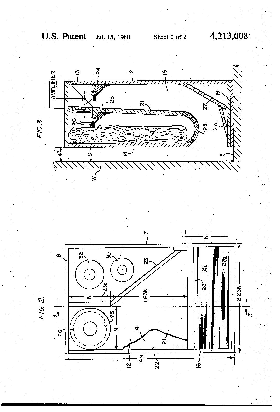
H. F. Olson's 1940 patent compound horn...
-
One of the drawbacks of a LF scoop is the footprint tends to be large being that it is a PA-type design, and for domestic use, if it is larger in footprint (say 24x24) than the La Scala, again, is the extra 10Hz of LF extension worth the size and trouble? Here's another of the smaller footprint variety, which I call "full-range small-signal" types, rightly or wrongly... I am very suspicious of the actual LF response of this type of design.
-
There are a bunch of scoop designs, but I find them to be limited to around 50Hz due to horn mouth size and exhaust route (1/4 placement is typical). Here's one...
-
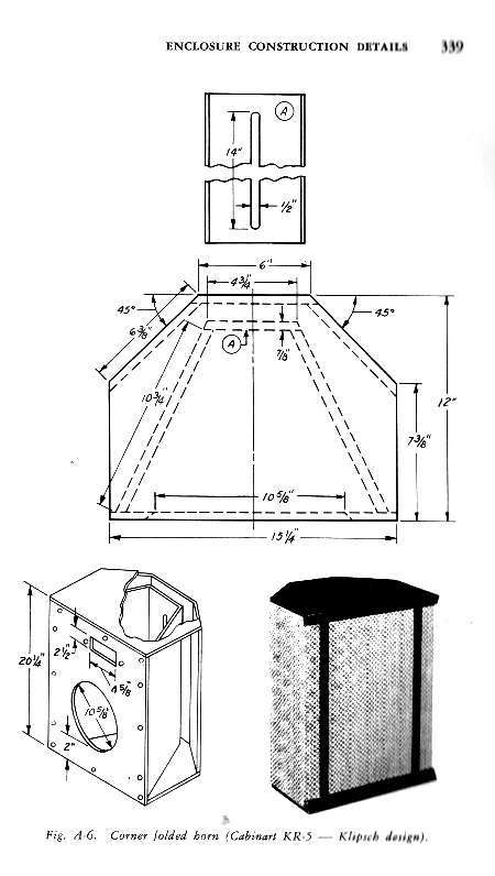
It's says 14" x 1/2" or 7 sq. inches total as seen in Fig. A (it's only a 12" driver). Interesting, the Klipsch Shorthorn uses a 36 sq. in. slot! Didn't it also use a 12" driver? Something's fishy! Well, not really, this is a much smaller cabinet than the Shorthorn. However, the drawback to the "shorthorn-type" corner rear-loaded enclosures is that the horn itself is very short compared to LF wavelengths, so naturally, it was not as good as some of the other designs that used a longer horn pathway. This isn't altogether bad, though, as mentioned previously, peaky LF response can be exploited or controlled usefully. Unfortunately not in this type of design which cannot take any channel "stuffing" to lessen the reactance.
-
Ah! back to simplicity, and an ability to free-stand or fit into a corner... This is a 1950's Jensen/Cabinart "shorthorn-type" cab licensed by Klipsch. Unfortunately, this won't go very low. However, it was determined to be competitive enough to warrant its existance AND a license agreement!
-
Like I said, at a certain point, it crosses a line - for all that size, weight and effort, wouldn't you rather build a Khorn instead? This Jensen enclosure is approaching that point, but I think it is probably still and easier build than the Khorn. Remember the Khorn has a top cabinet to make, too! But this is getting complicated! DM
-
Like I said, at a certain point, wouldn't you rather just build a Khorn? DM
-
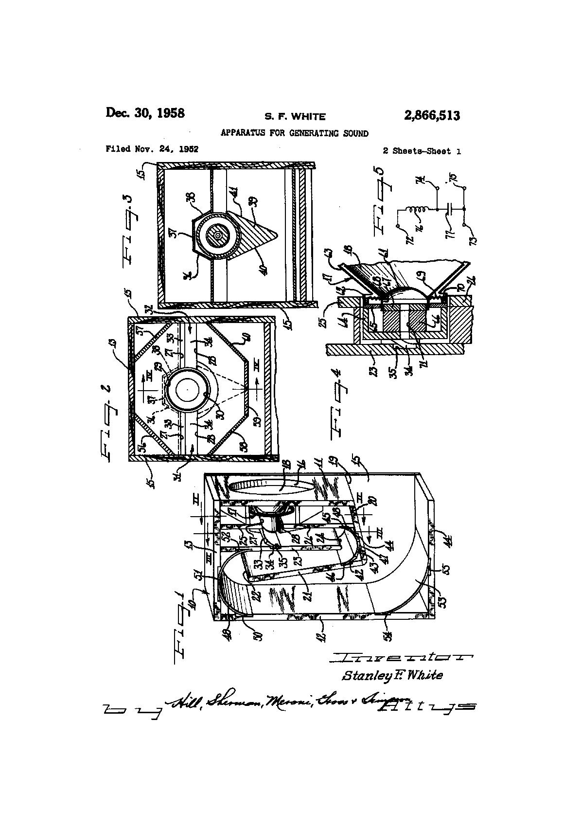
This Olson design (RCA) is reputed to do 94db at 27Hz, according to Bill Woods...
-
For free-standing use - they are all going to end up being "scoops" - that is the most viable "smallest" footprint design IMO. However my criteria is NO PA! If I wanted that, I'd have one already! I suppose you could call my design a "partial scoop" anyway. There is nothing new under the sun. There is a fine line between acceptable complexity and increased performance, and simply not worth it when other designs would work better - somewhere between just a box with holes in it and a front-loaded corner horn. Where that exact point is, I just don't know. DM
-
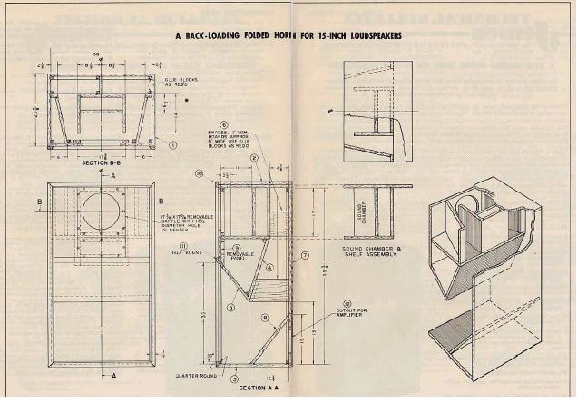
Alot has been said about the issue of time-delay and comb-filter distortion as being part and parcel of a rear-loaded horn. The same issues are there for a front-loaded horn, too, perhaps even more, as the front-loaded horn of some quality is typically 1/4 wavelength in overall pathway length. For a bass horn, that is likely to be a given that there is going to be phasing issues because of it. Probably less in the rear-loaded variety, as the pathlength is typically shorter. That comes with its own problems, of course. I'm just thinking... Rear-loading allows for a wider bandwidth (albeit lower efficiency) than a front-loaded horn all things being equal. Rear-loading requires physical limiting rather than electrical limiting in upper frequency response. Rear-loading promotes the use of higher Fs drivers, i.e., cheaper. Rear-loading is a wider bandwidth device than a reflex port, more efficient than a drone cone. Combinations of all of the above are possible.
-
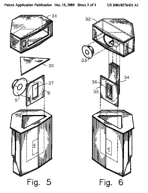
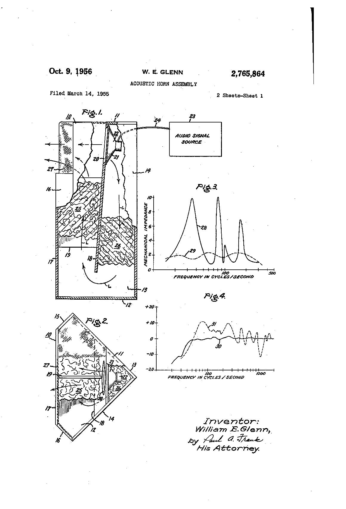
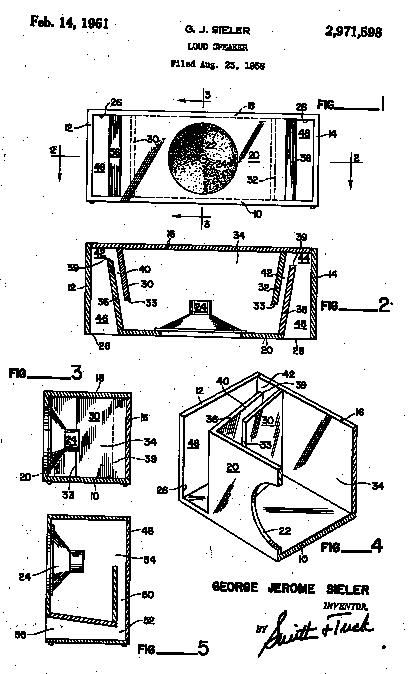
Which brings us to this, the 1950's patent to Glenn of General Electric. A "must read". DM
-
The Tannoy GRF is far more work to build than the Khorn! It could be that it was intended as a show-horse for the Tannoy Gold-15 coaxial driver, etc. but it stands 60" tall as a single unit and must also weigh a ton! That is a lot of work to build and ship, so if it doesn't compete with the Khorn and its ilk, then I have to wonder, why bother? The answer (apparently) is that it PROBABLY does actually compete effectively. It may not be economically viable, of course, but sonically I suspect that it has its own set of attributes which could make it an somewhat "equal" contender. Anyway, I'm not going to do a full 1/4 wavelength rear-horn, as there are already front-loaded designs that do that quite well. If I was going to do that much work, I'd build a front-loader for that reason - its a sure thing. But it seems that there is an area between the full-size monsters of the past and the too-small modern full-range 1/4 w pipe-types that seems not to be fully explored in the case of modern small Vas drivers specifically for domestic use. I'm not talking PA designs, I am talking about strictly domestic designs, and a different set of issues. DM {edit} The cabinet shown above is what I'm talking about - the full-range driver (Lowther, etc) type with the typically too-small mouth size for an effective non-peaky response. Now, it needs to be understood that peaky response is OK in certain cases, and this MIGHT be one of them. However, I have a couple of tricks up my sleeve to experiment with that issue. If the reactance peak(s) is lined up just right, you've got a wider-bandwidth device instead of a port, with the added efficiency of a horn (if it stays horn loaded across the bandwidth, which in most cases of too small/too short, it won't and will instead act like a 1/4 wavelength transmission line/pipe instead). That particular behavior COULD be purposefully exploited, but that would take some very careful attention, which I think most designers avoid. Look for absorptive material (damping) in the pathway in such a case. Even 1/8th space placement isn't going to give enough boundary reinforcment to even approach a legitimate mouth size in the case of the above horn, IMO. Back to the too-small horn mouth with too-short pathway, it is "acceptable" if only a small "section" of available bandwidth is horn-loaded, especially the case for low-SPL applications like the "lone girl with the guitar"-types, exactly NOT one of my criteria! This is the realm of the small-signal full-range driver (which really doesn't put out alot of low frequencies anyway), certainly not my cup of tea.
-
The large Tannoy rear-loader...
-
The better the LF response, the large the horn... as an example, the Jensen Corner Imperial.
-
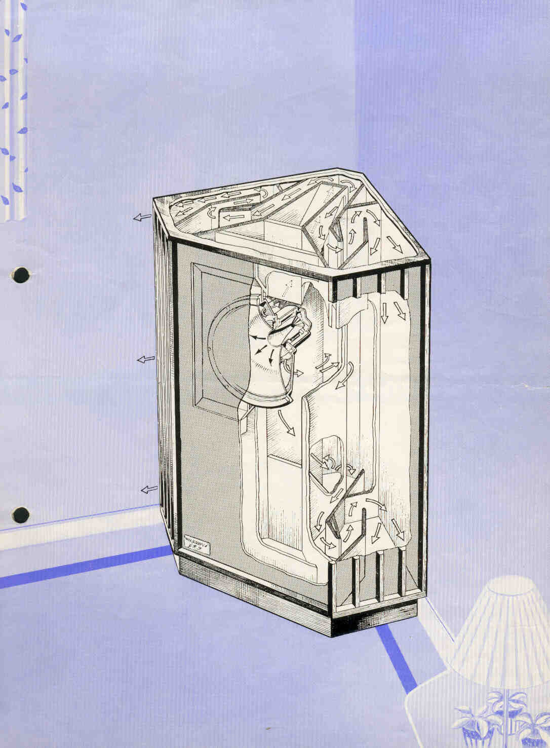
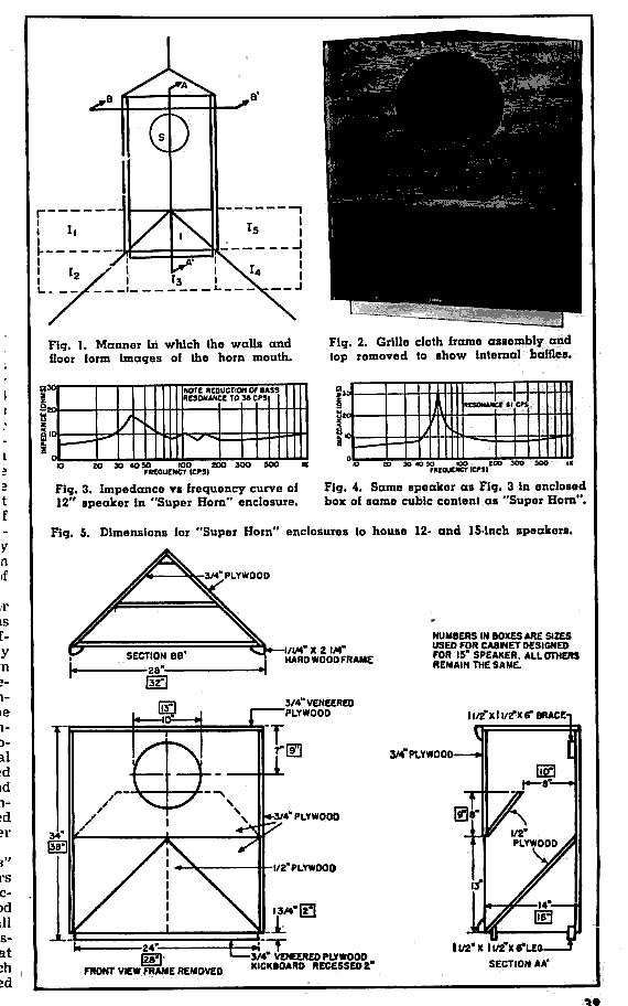
The famous Gately "Super-horn" even mentioned by PWK (in a humorous manner as representing a "new breakthrough in horn design", along with his own Shorthorn)...
-
More examples...