


radiogram
-
Posts
142 -
Joined
-
Last visited
Content Type
Forums
Events
Gallery
Posts posted by radiogram
-
-
Loudspeaker sensitivity ratings are specified based on Power and (@ 1 Watt/meter) and not Voltage. This would imply that the SPL will increase with increased power into the speaker and decrease with decreased power into the speaker.
This would mean that two different speakers with same SPL rating but different impedences will have the same SPL at different voltages across the speakers for the same wattage.
So here is my confusion. If this is indeed the case then would not a speaker’s acoustic frequency response be the inverse of the impedence curve? Let us assume we a have high current solid state amplifier with high damping factor (voltage source) capable of supplying enough current at the lowest impedence and can maintain same voltage.
Now, wherever the impedence is lower, the amplifier is going to supply enough current so as to maintain the same voltage. Thus, the lower the impedence more the power and if SPL is based on Watts then, consequently more SPL. This again would then imply an acoustic frequency response that cannot be flat but one that will track the inverse of the impedence curve.
If the SPL sensitivity were instead based on Voltage and not power, then it will result in same SPL at any impedence.
So here are my confusion questions:
1. If the above is true then it would seem that an amplifier that actually lowers the voltage to maintain same power at lower impedence is preferable so as to have the same acoustic output since SPL is Watt based? – Totally against well established design that a low impedence voltage source is the way to go.
2. Is any of my above analysis correct if we base SPL as dependent on Wattage ? If not, then where did my understanding or application going wrong?
-
You are thinking like someone who understands filters to some degree!
Al - You are quite right. While I do have some background in these, but as you have rightly preceived only to some extent. While I did formal courses in Filter Networks (I believe we used book by Van Valkenberg!, among others), Signals & Systems etc, as part of my EE, I never really practised that discipline, having swithced to computer Networking & Telecom Software as my Career. Looking back I regret having strayed off from my passion - Analog, RF, Phased arrays, etc.
Anyway, thanks for your explanation. It confirms my guess that klipsch had their own definition in mind (and that too not seemigly a consisent one), when they specified the crossover frequencies.
I also did not think about the component losses you mentioned. Appreciate your time and feedback.
BTW: I did some measurements today and I found that I have a 10% loss in signal voltage in the range 12000Hz and above (very much in full passband) with a 4uF Sonicap in series compared to without.
Amp Out ------8 Ohm Resistor - Voltage @ 12000Hz = 1 Volt
Amp Out ------|| 4uF------- 8 Ohm Resistor - Voltage @ 12000 Hz = 0.9 volts
Is this acceptable?
Thanks
-
In Klsipch Hertiage speakers what does the crossover frequency really stand for? Is it the frequency at which the electrical outputs of the different sections actually cross OVER (i.e. the point at which the plots of the two sections meet, as is normally defined in classic theory) or is it based on -3db or -6dB point of just one section taking over from another section ? The reason I have this confusion is because, first of all, for the older heritage speakers, the mid sections are run full out in the highs (no bandpass) and its electrical response will never cross the high section and secondly due to the following:
Take the following examples:
1. Circuit 1 (Type AA). - ----II (13uF)-------Tap5---T2A---Tap4-----K55 - The crossover frequency is specified as 400Hz. Now assuming an average impedence of 14Ohms for k55 (effective impedence 2* 14 = 28) , the -3dB point is 437Hz. So the 400Hz roughly corresponds to -3dB point.
2. Circuit 3. (BEC's cornscala) ------4 uF--------CT125 - Specified crossover frequency is 4500 Hz. Taking 8 Ohms for CT125, -3dB point is 4973Hz. Here the specified freq seems to about the -3dB Point.
3. Circuit 2 (Heresy). ------|| (2 uF)------K77 - The crossover frequecy is specified to be 6000Hz. Taking 8 Ohms for K77, the -3dB point is 9947Hz and -6dB point is about 5800Hz. Here the 6000Hz specified corresponds to about the -6dB point not -3dB.
Now classical theory dictates that for first order crossovers the ideal crossover point is the summation point of -6dB of both the sections for flat electrical output at and around the crossover frequency. Of course, this is purely based on eclecrical output only without any regards to acoustic output and such theory will work only if all the drivers have flat acoustic output at that crossover frequency and ideally even an octave beyond.In reality of course this is not the case.
In any case, can someone throw some light on the what the specified crossover frequencies is supposed to really mean?
Thanks
-
IB Slammin:
If you look at my original post under Experiences, you will see the following statement from me:
“Please note that whatever impressions I have given are purely my subjective experience based on my preference. I do recognize and respect that fact that others have different experience and preferences and that you may not agree with my experiences."
I do recognize that everyone has his/her own preference and rightfully so and also as you said that at times one may not be able to really explain objectively why so. Ultimately the proof is in the pudding and it does not really matter why. However, many of us have this academic curiosity as to understand why, in such situations. And then there are even times when I am not fully confident of my ears, I look for a scientific reason to see if I can use it to help decide.
So it is mainly in this light of such academic curiosity that I have pondered upon my questions on “To Cornscala or Not” and it is mostly on objective issues only and as we know only objective issues can be discussed or argued meaningfully. Being in this hobby myself, with my own opinions and preferences, there is no way I can throw stones from a glass house by questioning or criticizing others choices. I hereby clarify that it is not my intent.
When I prefer something over the other, I try to find out 'why so' objectively, sometimes I succeed, sometimes not, sometimes do not know what to or how to measure and sometimes I see if others have an answer. Similarly when many people seem to have a consistent preference of one over another, I would like to know if there is any objective explanation for that to appease my academic curiosity only to understand and learn and clearly not a demand for justification. I recall similarly JWC at some point asking why is the Cornwall III better when somebody reported so. If one can come up with an objective reasoning – great – it is an added bonus for me and can serve to educate me further – If not and one says I am unable to explain, but this is what I prefer – Fair Enough - as I am no exception to this myself in certain cases! Nevertheless, I may continue to probe to see if someone else has an answer.
( If you ask me scientific explanation why is it that the Yamaha preamp does primary duty in my system and not the NAD - My answer - “Can’t explain”!! This unanswered curiosity has nagged me for quite some time. At times I wonder if it is all only in my head ).
Thanks for your feedback & Cheers
BTW: 110 dB!! Wow! I doubt if I ever exceed 100dB.
-
JWC:
Thanks for your feedback. Your Cornscala project is yours and whatever choices you made as long as your are convinced, it is justified no mater what I think.
In any case, my conclusion that Cornscala may sound different but not necessarily better, is not just based on my subjective preference. It is also based on objective and scientific aspects that I have put forth in my pdf. Besides, my measurements (although I have to admit, my measurement tools are rather basic and far from being professional) did not show anything to the contrary nor have I seen any objective and scientific proof from anyone so far showing why Cornscala is better than Cornwall. If anyone would provide one and enlighten me with objective & scientific proof why a K55/K400 mated to a Cornwall bass bin, is better than a K53/K701 or a K52/K601, I will be happy to correct myself and accept that my impression is purely based on my subjective preferences alone.
Anyway, while BEC provided me the inspiration it was your project and your cs4.pdf that actaully motivated me and made me beleive I can actually build something like this and if not for your project I doubt if I would have dared embark on this.
As far as Cornscala over La Scala - I am already in agreement with you in my conclusions I have already posted.
Thanks & Cheers
-
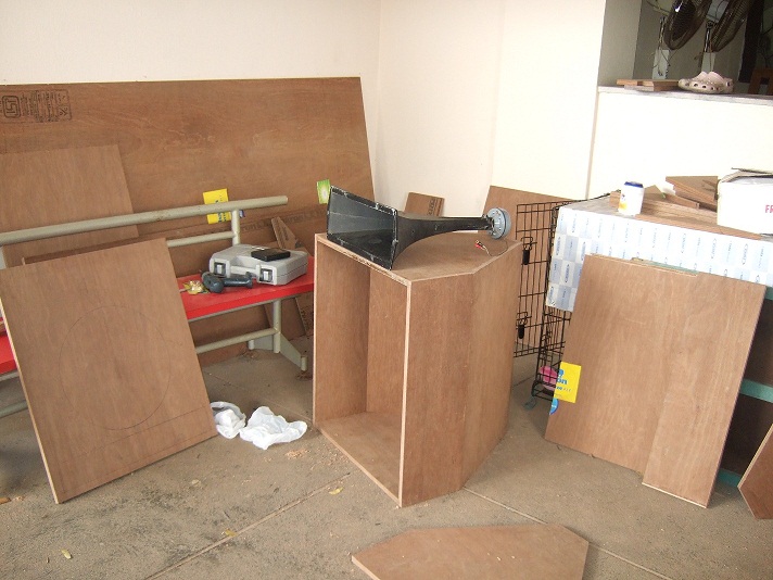
Early Stage of Cabinet in progress

-
-
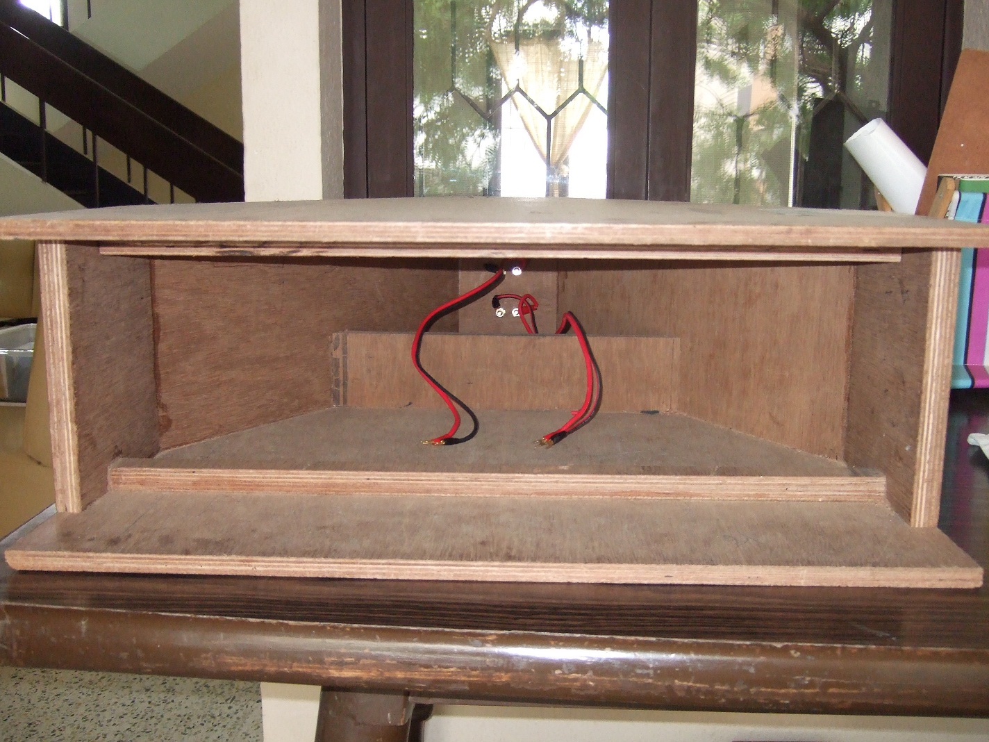
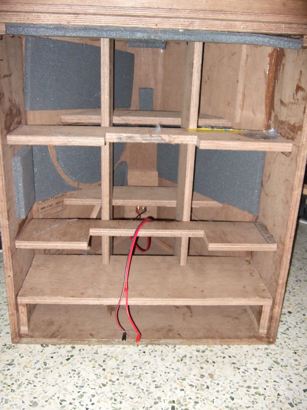
Bass Bin Inside.
-
-
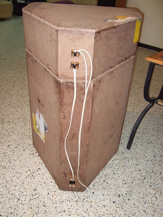
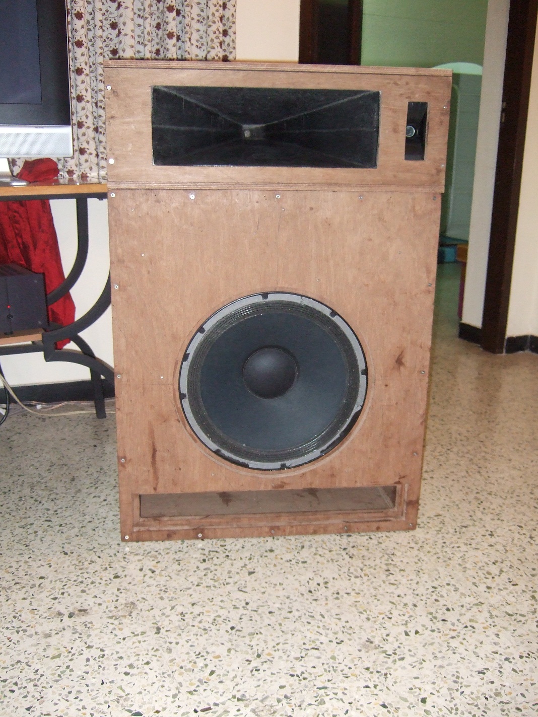
Front View - The speaker is yet to be cosmetically finished.
-
Attached here is a pdf with my cornscala & cornsey expereince.
Please note that whatever impressions I have given are purely my subjective experience based on my own preferences. I do recognize and respect the fact that others have different experience and preferences and that you may not agree with my experiences.
-
Deleting this Post.
-
Deleting this Post
-
Thanks Dave. I accidently ran into your website yesterday. You seem to have a lot of interesting options there. Keep it going.
Regards
-
I am new to the forum as a registered member but really not knew in terms of reading and following a lot of posts & threads. I want to first thank all the members for sharing their Klipsch experiences and providing a lot of knowledge and help to other members. I have been resisting joining any audio forums for years, but I would like to share my Cornscala (or Hornwall as I would like to call it since its physical form is similar to that of Klipschorn rather than La Scala) experience and hence here I am.
I wanted to build a custom cabinet for my Heresys to extend the bass response. That’s when I contacted Bob Crites for his suggestions. He instead suggested that I build a Cornscala. I went through his project and also JWC’s work posted in the Klipsch forum. Thus my Cornscala project started.I have attached here documents that show my objective and goals.


SPL Ratings & Power Response - In the Land of Confusion Again
in Technical/Restorations
Posted
Deleting post due to issues with line feed.