

ToolShedAmps
-
Posts
207 -
Joined
Content Type
Forums
Events
Gallery
Posts posted by ToolShedAmps
-
-
KT120? I have never seen a KT160.
If you like tube aesthetics I recommend checking out the gas regulators. I have changed my mind on my latest build about a million times and I finally have decided on using gas regulators in an over the top external power supply. That purple glow is intoxicating!

Sorry, Type-o, KT-150, here is the data sheet.
-
Yeah I am the last person that should bring up efficiency. I guess what I should have said is I would save the type 83 for a high powered class AB power amp. But they do look pretty cool, I wish my Hickok tube tester had it on the exterior so I could look at it while testing tubes.
I think it's best attribute is the 15v drop. You can design excellent "choke" loaded power supplies with it and get away with using a minuscule input cap as a "shock absorber" to be able to use open-frame chokes. It really is a wonderful piece of equipment. In the case of using it at max current and high voltage, you would normally have to use 2X 5U4G's Paralleled to do the same thing.
I have on my drawing board the design for Mono-blocs based on my Transcendence12 stereo amp that uses paralleled KT-160's, theoretically, output is in the neighborhood of 32 watts single-ended that uses the 83. -
Yes sir gas rectifiers look cool for sure!
The 83 rectifier is a pretty heavy duty rectifier. It will only drop 15 volts no matter the load up until the point of saturation. My opinion is it's kind of overkill and inefficient for the application. Since you aren't building guitar amps and compression from sag isn't a design goal, and still it's class A so no sag anyway. The only other reasons for tube rectification is slow B+ ramp up which isn't going to happen with directly heated rectifiers, that leaves noise. SS rectifier noise can be mitigated by the use of fast diodes and or snubber networks across them, I like UF4007's. You can then use two OD3 gas regulator tubes in series to regulate the B+, you still get the cool gas tube look but they are also functional, unlike a directly heated rectifier tube for a preamp
Or have your cake and eat it too, go with a transformer with a 5V 2A winding and use an indirectly heated tube for slow B+ ramp up and then use the gas regulator tubes for looks and regulation. You need to shunt the regulators with a small value cap, 100nF max I believe. Just my 2 pennies. This is your build, I just like to help give options.Ahh....I don't believe in efficiency anyway, if I did I'd probably start designing CCS loaded transistors with FET followers, or something....
I'll just do it the empirical way, I'll build the PS and the circuit, load it, then use my variac at several voltages from 118v to 125v with each rectifier, find the "best" average voltage drop with each Rec., and let everyone know.
This solution will then also allow for individuals at the extreme ends of the scale to adjust accordingly. Sound good?
Thanks,
Matt.
-
So if one of you has the ability to run a sim with that 115v input rating (assuming MOST of us actually have 118v at the wall)
The power company is allowed to run 114v to 126v (ie: +/-5%).
It is very common to see 120v to 124v at the wall in my area.
miketn
Wow, thanks for the info....now THAT must really play havok with all of the excellent vintage guitar amps in your area! Or ANY old power transformer for that matter.
-
....really isn't necessary when you run get yourself another beer (or get rid of the one you just had......
Hold the phone here did someone mention beer?
I think I will have a Troeg's Perpetual IPA right about now. I usually reserve my beer drinking night for Wednesday at band practice but I skipped out last night because my stooopid back is killing me. Yeah I know I am a wimp. So here I am drinking while my better half is at work (I feel no guilt).Back to your amp. The filament transformer might be a bit tricky to do from paper since I can't find published winding resistance specs. I could extrapolate it from load data but I need two data points to calculate. So where we stand is if you use the type 83 you know that w/ the primary voltage @ 120 your heater voltage will be 5.2V, no big deal if you ask me. How high will it get with the type 80? That's the million dollar question I guess. The 5U4 pulls 3A, maybe use that instead of the type 80?
Unfortunately we can't use the 5U4G, it uses the standard Octal base while the 80 and 83 share the same pin-out on the UX-4 base. I think honestly, part of the "fun" of this Line-Stage is that guys (even the ones with SS amps and have never owned a "tube" anything) will get the chance to play with valves that are literally "a Gas".
Come-on, you know that running a Mercury Vape or a "huge" Globe gits' you grinning every time you look at it. Mo' beers = mo' grins! -
 1
1
-
-
I fear the standby switch might cause a popping sound through the power amp. It could be easy to add a 555 timer and a relay to mute the outputs until things are warmed up but that's probably overkill. Or the easiest route is switch to an indirectly heated tube rectifier so things ramp up slowly. Sorry I know I am a pain in the butt
Switching to the 300 series might be easier but sticking with what you have isn't too tought to work the bugs out, I know Maynard uses the 200 series all the time, he is a wealth of knowledge and won't mind helping I don't think. The 83 pulls 3A and the 80 pulls 2A, I say pick one and design specifcally for that because with the type 80 and the 115 primary you will be way over the 5v.
Matt, have you considered simplifying things and using something like a 270CAX or 270X which have a 5V/2A winding and the dual primary voltage options? That would be less costly than using the 269JX and additional filament xfmr for the rectifier. As far as a standby function goes, you could put around a 47k resistor between the high voltage CT and ground with a switch across it, or put one between the rectifier and input cap. That would keep the caps somewhat charged and should eliminate any concerns about popping when going in or out of standby. If it were my decision, I'd forget about a standby switch altogether. The 6J5s are running well below their rated plate dissipation and should, with controlled filament voltage, last "forever" anyway even if never turned off.
Maynard
Hi Maynard,
Yes, I have considered using the 200 Series (as evidenced by this initial PS design), however, although it would alleviate the need for the 5v tranny (but not really unless the design is limited to the 80 Rec) it still has the non-dual primary problem (what I mean is, "actual separate windings that are either put in parallel for 120v or series for 240v input) these are the only Hammonds that I know for sure don't "Buzz". Like I said, I normally either use the 300 Series or (with enough lead-time) the dual-primary Edcor's.
Also, to clarify, you are suggesting a 47K resistor in "series" with the standby switch to ground? Or, "Parallel" with the switch to ground?
As for limiting the rectifier choice, I think it would be pretty "neat" if we could figure it out using the 5v filament tranny, I'm guessing as it is only 5v @ either 2 or 3A, a nice Carling DPDT ought to be able to switch in the required dropping resistor for each? So if one of you has the ability to run a sim with that 115v input rating (assuming MOST of us actually have 118v at the wall) the value of the dropping resistors could be realized. I think that the extra $15 or so in parts would be worth the ability to "show off" a Merc and shift the O.P. (If JPM would be so kind to run the distortion sim again with the 320v supply voltage we should see a difference in the distortion plot, all other things being equal).
I will change the Power Transformer to the Hammond 369JX, as it has the "real" dual-primaries and it is less than $20 more than the 200 Series PT in the original schematic.
Thanks gents,
Matt.
-
The voltage output of the Hammond power xfmrs tends to run fairly high, especially if wired for 115V. I recommend using the 125V primary of the 269JX in any situation where the line voltage is above 117 or so. Even doing that, the 6J5 filaments are likely to be presented with over 7V necessitating a higher value dropping resistor than JP suggested above. Same for the rectifier filament xfmr which has a primary designed for 115-117V- voltage will have to be dropped for that tube as well. The resistors should be installed in a way which allows the generated heat to escape. I'm not a fan of heat build-up under the chassis. And, as JP pointed out, a bleeder should absolutely be installed for safety. The 6J5s are not going to draw enough current to allow for even a moderate bleed as their cathodes cool off.
Maynard
Hi Maynard,
Thanks so much for pointing out the 5v transformer is rated at 115v at input as well. This is a great catch, perhaps what we should do is focus our attention on dropping the voltage on the 5v tranny and switch to the 379JX (although it's a bit more money) on the PT for the reason stated by JPM and so that we aren't bothered by that nasty electro-mechanical buzzing that single-primary Hammonds are known for. Great, this ought to work well then.
Thanks again,
Matt.
-
The standby switch is pointless unless the power supply caps are not rated for the higher no load voltage condition, other than that these voltages are not high enough to produce cathode stripping. Also most people use electrolytic capacitors which have a high dielectric absorption so instead of the caps bleeding off on their own they actually do quite the opposite. That power transformer's high voltage secondary winding is rated for something like 4x the current you are using it for, I hardly doubt it will notice the 1mA of extra current draw a 330k bleed resistor will add.
I don't mind helping with the remote control power supply, let me know it's power requirements and I will do my best to assist you.
Excellent! Let it be known that I don't want to be considered "un-coach-able", we will add the 330K Bleed-Down Resistor to the schematic.
However, we will still maintain the "Standby" switch for those of us who prefer to leave our Line-Stages "Cookin' and Ready to Roll" at a moments notice.
Thanks again,
Matt.
-
Good afternoon Matt, First thing I would like to comment on is that there is no safety bleed resistor. Not necessary but a good idea to add one.
That power transformer's 6.3 winding is rated for 2.5A and you will be only pulling 600mA. I calculate that the voltage will be 6.6V across the heaters, IMHO that's too much and will shorten the life of the tubes. I personally like to keep it under 6.3V and above 6V. To get 6.2V across the heaters I suggest using a .6 ohm resistor in series to drop .4V.
The HV secondary winding resistance of that transformer is 175 ohms from red to center tap, you could up the capacitance to a max 100uF without stressing the rectifier but the ripple is already low enough it might not matter.
-JP
Howdy JPM,
Now this is the kind of "discussion" I think most forum members can learn something from.
I have not added a "bleed" resistor in the Power Supply for a couple of reasons, as I normally like to include a "Standby" switch, I have found that dumping the voltage in the caps really isn't necessary when you run get yourself another beer (or get rid of the one you just had
), additionally the capacitance is so low that they will naturally "bleed-down" after a listening session in less than an hour. Furthermore, if you have ever measured the temp. of a PT (under load) with and without bleed-resistors you will find the PS runs hotter "with" them.Great catch on the filament voltage!
Wow, what a waste of perfectly good current. , As this PS was designed this morning (and has yet to be built for practical application and Empirical study), along with the decision to include a 6.3v power indicator lamp or not to include one. As well as still trying to decide (and YOU would be an awesome help for this), using a large portion of this winding (perhaps through a voltage-doubler) to provide the power to a motorized volume control. (It seems as though EVERYONE wants one these days!) Also, I have to apologize, I normally use the Hammond 300 Series PT's which have dual-primaries and have taps for 120v/60Hz instead of the 115v/60Hz primary on this PT. Anyway, NORMALLY what I do with a new design is this: Build it, then measure voltage "under load", do the math and then add the series resistor (even if the current draw puts the heater voltage at exactly 6.3v I will add a resistor anyway as I think the tube "sounds" better running them slightly "starved" at approx. 6.1-6.2v).The reason that I am not running MAX capacitance is for the reason I stated when I posted the schematic. I have designed an excellent power supply with LOW capacitance so that DIY'ers (And MYSELF) can use either Film and/or ASC Oil Filled caps instead without having to build a separate chassis for the power supply. Also, I really didn't want "rise-time" to be impacted negatively by the increase in unnecessary capacitance, this Power Supply is LIGHTNING FAST, coming up in 0.5ms So, If someone (DIY'ers or MYSELF) wanted a Line-Stage they could live with indefinitely (provided there are enough inputs, two pair of outputs, AND a motorized volume control), this is a pretty good candidate.
Anyway, I am waiting on the TKD motorized pot and Glasshouse IR Controller kit to arrive from the UK that I will be using in this build, so if you have any ideas on how to power it with the unused current in the 6.3v winding it would be much appreciated.
If not, I'll just have to order up the 12v DC "wall-wart" and add the connector to the back panel.Thanks,
Matt.
-
Howdy All,
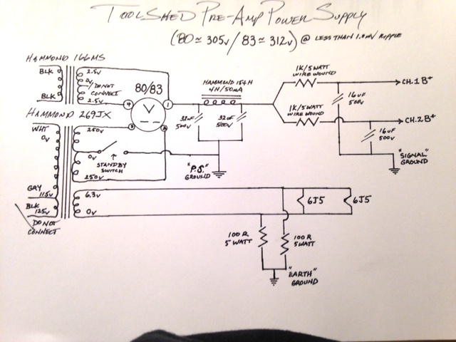
My initial plan had been to offer two different versions of Power Supply to drive this circuit. The less expensive supply offering economy and a more expensive supply featuring ultimate performance. Well......to avoid confusion, I have decided to design a Power Supply from scratch to drive this Pre-Amplifier. This supply offers FANTASTIC performance at LESS THAN 1.0mV ripple at stated current and voltage, AND, I have "upped the ante" in terms of "Cool-Factor" (especially for those "getting their feet wet") in that the rectifier will be either an 80 or for those of you who think that a "DeForest Audion CX-280 Large Globe from the 20's" isn't "cool enough", the PS will also accept the 83 Mercury Vapor Rectifier.
Yep, super cool, super performing, AND....if built with 'Lytics, it won't break the bank. However, because the capacitor values are so low, if you would like to go "Whole-HOG" and dump the electrolytics in favor of film or oil, have at it!
Take a peek.
]We'll open it up for comments and questions (if any).
Matt.
-
Good Morning All,
For those of you who are interested in building the "low-distortion" version of the pre-amp (which is the version I would suggest for pairing with any of my amplifiers, SET's in general, OR many of Nelson Pass's Solid State S.E. Designs) see the schematic attached below.
I will draft the two different Power Supplies at some point today and attach them as well.
Cheers!
Matt.
-
Just an idea since you are doing two octal sockets. I messed around with a 6V6 for a linestage in the past. You could also offer a brute force linestage. Less gain and plenty of current to drive heavy capacitive loads, lower rp than the 6J5 too. With 1Vrms input you get 8.5Vrms out @ .2% THD. Not too shabby. Also if your cheap like me you could even use some cheap tv sweep tubes.
Edit: R1 and R2 is my model of a volume pot so use appropriate grid leak and volume pot.
That looks pretty interesting, I may stick one together at some point and give her a listen, but, for now we will go with the linestage I have designed. The 6J5 is a very "musical" tube that has yet to hit the "endangered species" list, in fact, in addition to using it in a linestage, I use it as a cathode follower in my 45 amp.
-
I never sweat low powered tube amps with an open load even under signal conditions. I don't practice it; i.e. i always have a load hooked up but in theory most windings insulation are rated for over 1kV, anything with a plate voltage of under 500v can't swing that high to cause shorting.
Good practice is good practice, you never know when someone in the DIY community is going to salvage a paper and shellac tranny out of some old console and "forget" to hook up the speakers.
-
1
-
-
Alright, here we go again, I guess I just like a certain amount of "SAG" in my PS.
What are you measuring for a current change in the PS during signal? Class A operation generally doesn't sag since the average current draw doesn't change.
And thanks for the schematic!! Any valve choice is better than the 12AU7 IMHO
And, you are absolutely correct. ALL Class-A, Single-Ended designs draw "constant current" regardless of load, that's why forum members should be informed to NEVER turn on a Single-Ended Class A amplifier without speakers attached as you may damage your output transformers.
Matt.
Matt, I need to take exception to your statement as I don't want users of single ended amps to have any undue concerns. The constant current drawn by class A single ended amps is a dc condition only. Under zero signal conditions (i.e. no music playing) it is of no consequence whatsoever whether the speakers are connected or disconnected. Both SETs and SEPs can be open circuited with no damage to either the tubes or opts. Under signal conditions (such as someone accidentally forgetting to reconnect their speakers), a triode and its opt is very unlikely to be hurt, and pentode amps using voltage feedback "should" be able to handle it as well. Obviously, one should always check things over before firing up an amp. But if, as we all occasionally do, we forget to connect the speakers, there's really no need to panic.
Maynard
Hi Maynard,
We can agree to disagree.
I've seen a couple of OT's go "open" in my time, that's why many old timers still put an 8 Ohm/12 Watter across the outputs "internally". Matt.
-
That's cool, this isn't a phono pre, we don't want it too linear/sterile and a CCS plate load might do just that. I think the distortion level and spectrum look good now.
As far as setting bias goes here is how I look at it. Transconductance and plate resistance vary from tube to tube, mu is the most consistent parameter. If you set current through the device you will still have different voltages at the plate and cathode due to the slight differences in plate resistances from tube to tube. The plate load resistor and internal plate resistance form a potential divider, the current set by the CCS will develop different voltages due to the different plate resistance. So to summarize current will remain constant (it does anyway because it's class A) but voltage will change due to plate resistance differences. I think I did some experiments with this by setting up a test jig. I set current at cathode via CCS, and set a fixed plate resistor. I then placed different tubes in and measured different plate voltages at quiescent operation. This was on a regulated bench power supply. If anyone wants to try this too that would help to make sure I am not crazy. I will try and set up a test jig later this evening.
Matt, I think Mike and William bring up a good point in that someone with a very sterile SS setup might actually want 1-2% THD added. Others who run SET like amps w/ 5% THD might want the preamp to be cleaner. Maybe as a prerequisite they could inform you of their setup and maybe they can build or buy it either way, volume control in the rear or in the front. Both circuits are fine but have different characteristics.
I COMPLETELY agree with everything you just said. That is why I presented the design the way I did, Version #1 is the design that would pair best with SS amplifiers (Higher distortion, mostly 2nd order), and the "Revision" which, to be honest, is actually MY Pre-amp design (actually revised for Version #1 to be more compatible with SS Amps). So, no more "funny business". DIY'ers can build the Pre as either V1 for use with SS Amps or V2 for use with S.E. Tube amps (During the build, we will allow for connection points that the DIY'ers can use to CHANGE their build from V1 to V2 in the event they buy or build a Tube Amp).
As for the comment about the voltage change depending on a "specific" tubes' plate resistance, I agree, however, we as designers (just like voters) have to make informed decisions and select the topology (or candidate) that most closely relates to our Utopian ideals. What I have stated regarding non-matching tubes has been proven by my own empirical data over the course of many years now. I started using the lowly LM317 as a current sink several years ago, and in fact, they still exist in several of my old builds, none the worse for wear.
So, we will get on to the Power Supply discussion shortly, perhaps later this afternoon.
Matt.
-
1
-
-
So, over the next couple of days, we will put together a "Bill Of Materials" for those of you who would like to build this Pre-Amplifier. The "BOM" will be divided into three different parts: 1) Circuit, 2) Less Expensive Power Supply (Tweaked supply from the original project) and 3) More Expensive Power Supply (my own design, typical of my amplifiers). Additionally, some suggestions will be provided for the other necessary hardware and chassis parts.
Cheers!
Matt.
-
FWIW the CCS in the cathode doesn't really help or hurt things. If you want to linearize it you would have to CCS the plate. I actually like LED's at the cathode, they are cheaper than capacitors.
I like the "sound" of a purely resistive load. And, I'm pretty sure everyone else will too.
By "forcing" the quiescent operating current out of the tube, we can then "tweak" the supply voltage till we achieve the most "pleasing" operating point. Additionally, because I'm not a "rich" guy by any stretch of the imagination, by using a current "sink" to bias the tube we have the added benefit of NOT HAVING TO BUY "MATCHED" TUBES. That's right, as long as the tubes are of the same construction and known to be "good", we can just stick them in there and enjoy. This will be a "Killer" preamp. One that I'm sure everyone will really take satisfaction in owning/building. Matt.
-
1
-
-
So current source the cathode at 5.2mA, fully AC bypassed. Volume moved to front end. Same gain 22db. 1kHz sine wave input. Output 1Vrms is < .2% THD.
Now this is the pre-amp we are going to build.
I think there are a fair number of DIY'ers who can handle this build without too many problems. If they have any, hopefully everyone here is willing to give them a hand. I will modify the existing Power Supply design to increase voltage to an acceptable level for this circuit. Additionally, I will provide a 2nd Power Supply design of my own (for those DIY'ers who would like to extract every iota of performance from this circuit) which offers approx. 0.4mV of ripple at stated current. -
Looks like up to 22db gain. I ran some quick simulations using the same parameters. Average source input of 1Vrms, 1kHz sine wave. The distortion spectrum looks better, mainly 2H, but still rather high at 1.8%.
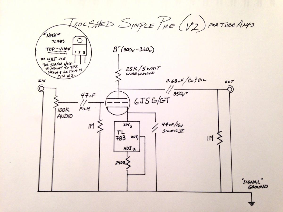
Ok then, this is Version #1, straightforward while still retaining the pot outboard of the gain-stage. Now lets rub it a hair.
Move the pot to the input, hang a 1 Meg resistor off the output to ground, throw out the 1K bias resistor and replace it with a TL783 (keep the bypass cap as it provides a good AC path to ground) use a 1/2 watt 240 Ohm resistor to set the quiescent current draw @ 5.2mA........Now what do you have?Matt.
-
Alright, here we go again, I guess I just like a certain amount of "SAG" in my PS.
What are you measuring for a current change in the PS during signal? Class A operation generally doesn't sag since the average current draw doesn't change.
And thanks for the schematic!! Any valve choice is better than the 12AU7 IMHO
You wanted an answer for why I don't like SS rectifiers, so, I provided one, actually, I believe there to be a difference in sound beyond the "scientific" breakdown of any power supply, if you don't believe me, build the circuit with both then do a "listening" test and judge for yourself. And, you are absolutely correct. ALL Class-A, Single-Ended designs draw "constant current" regardless of load, that's why forum members should be informed to NEVER turn on a Single-Ended Class A amplifier without speakers attached as you may damage your output transformers.
Matt.
-
Alright, here we go again, I guess I just like a certain amount of "SAG" in my PS.
The 1st thing you will notice about my "revision" is that there isn't a 12AU7 in sight. In fact, this tube isn't a "Dual-Triode" at all. It IS however approximately the same as 1/2 of a 6SN7 in it's own envelope. I've done this for a couple of reasons which I'll get into after you all take a look at this.
Ok, lets talk about this then.
Matt.
-
Good Morning William, Good Morning All,
My last post started to describe what I thought was interesting about the design. This post I will continue with another item that I find interesting and beneficial about the original design.
The "Ground Lift Switch", after reading through much of the associative feedback from the original build, many who had built this pre-amp had a bit of difficulty "wrapping their head" around this in terms of how it was actually done. In this build thread I will describe in great detail how to do this. Additionally, many DIY'ers can benefit from some of the grounding methodology that I employ as a "rule", many of my amplifiers are used on speakers that exceed 102db efficiency and are "dead" quiet.
We will talk about "Earth" ground, "Chassis" ground, and, "Signal" ground. This will be a great primer for those of you who wish to minimize noise in your own builds. I will not talk about grounding "theory" but rather, I will simply describe and execute the methodology that I have found to be successful regardless of application.
Secondly, the original project uses a power supply design that I find to be an excellent example of a "Tube Rectified" design in keeping with my own power supply design ideals. Those of you who want to design your own SS bridge or voltage doubler to employ a less expensive solution or perhaps use a power transformer you already have, please feel free. However, if you do this, please keep in mind that a SS rectifier imparts its own signature to the sonic "footprint" and therefore will no longer represent what the original designer intended.
My next post will provide a revised schematic (based on what the designer intended) of the circuit. Additionally, I will follow that up with changes to the power supply to support the changes to the basic circuit.
The last thing of note; if DIY'ers intend to employ (at some point) a "motorized" volume control, the value of the Stereo pot MUST be changed from 250K (per the original schematic) to 100K as there are no motorized 250K Stereo pots available. In an effort to maintain the "sweep" of the original designed in volume pot, we can detail how to "strap" a fixed resistor to the Stereo 100K pot for those of you who wish to build the pre-amp "straight".
Until the next post, Cheers!
Matt.
-
Y'all get on in here and we'll talk about this a bit.
The things that interest me about this design include; the use of a volume control "outboard" of the gain-stage. I will freely admit that I have NEVER done this before. However, from a purely pragmatic perspective, it is an interesting idea and it will be retained (unless of course there is some absolutely compelling reason it should not.) What is interesting is that it is not only attenuating "volume" but, also shifting the output impedance. AND, any "noise" being generated or induced by the control itself is not being "amplified", and only becomes a minor contributor to the sonic puzzle.
I VERY much like the simplicity of the design, in my experience "less stuff" in the signal path the better. However, I will side with a few individuals who concur with the idea that "universality precludes optimization". SO, this build will NOT be universal. If anyone out there thinks they need a pre-amp with nearly 35db of gain, please chime in and state your case. (You "Low Output Moving Coil" guys/gals need a phono-stage any way you dice it.
)Anyway, this ought to get the party started.
Cheers!
Matt.
-
Kirk, please restrict vendor type sales questions to PM, thank you. TSA, if you would reply in like, that would be good as well.
Thanks, Carl.
Sorry Carl,
Feeling "beat up on lately"
-
2
-


ToolShedAmps Modified 4S Tube Pre-Amp Build
in Talkin' Tubes
Posted
Good Morning Corey
I will state this for the benefit of all. I PREFER to use Edcor POWER transformers because they can be ordered with a 120v input rating primary. This alleviates the need for dropping resistors on the filaments (unless you, like me, intentionally like to run small-signal tubes "slightly" starved.) However, as 90%+ of my sales are "custom" amplifiers, the lead-time from Edcor (which can be as much as 8-weeks) generally prohibits their use as my customers rarely want to wait that long. I will be revising the PS schematic at some point this weekend to reflect the changes that forum members; Maynard, xxJPMxx, and myself have worked through. As part of these PS changes, I will note which Hammond part #'s to order, as well as (for those of you who can wait) the preferred Edcor part #'s.]
Corey, to answer your question, the XPWR001 @ $46 "could" be used IF you limit your rectifier choice to the 80. In my estimation, most members (whether DIY'ers or purchasers) would LOVE the option of a Mercury Vapor rectifier (83), I would recommend instead the XPWR136 @ $32, select the "dual-primary" option for another $5, and add the $20 LVP5-3-120 (5v/3A filament Tranny) to your order for a total of $57 So, for a cost difference of less than the price of a decent burger and fries you have the option of running the Merc
Matt.