Gints
-
Posts
26 -
Joined
-
Last visited
Gints's Achievements
Member (2/9)
2
Reputation
-
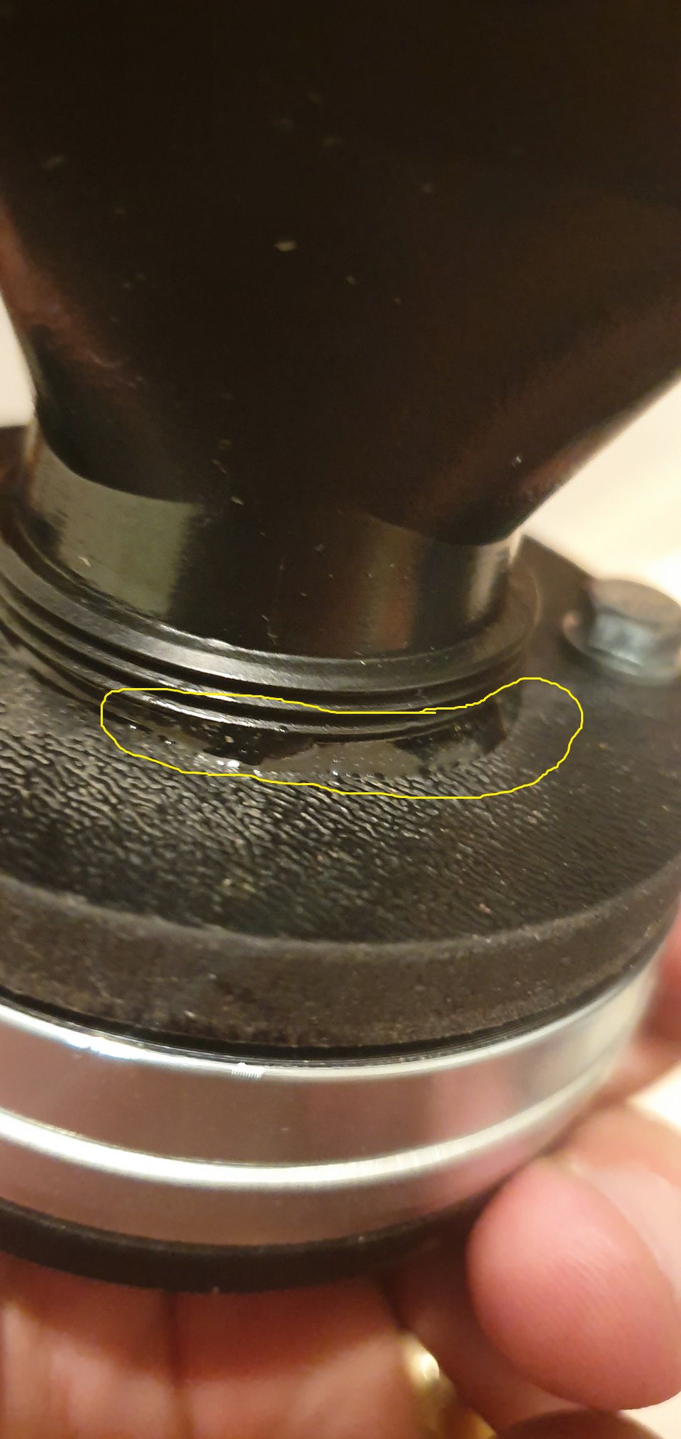
Okay. That worked. CT125 is now out. The 'Glue' I referred to is on the CT120 to go in, as displayed. These are brand new so I don't want to over-force things - looks like some kind of threadlock?

-
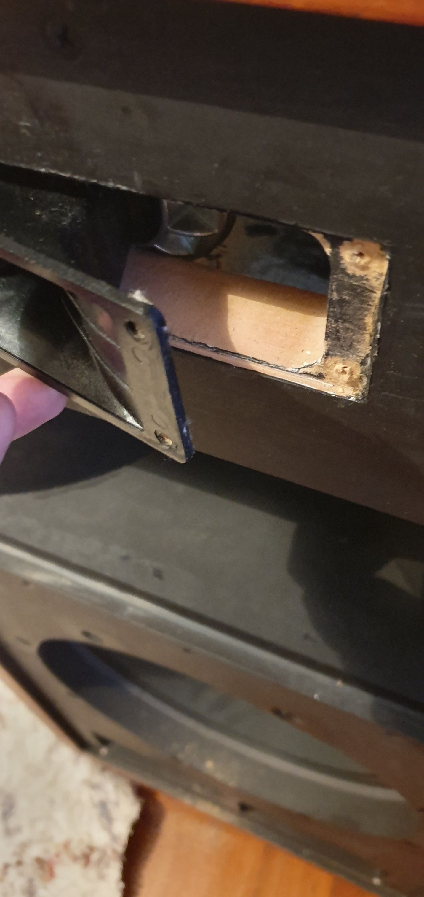
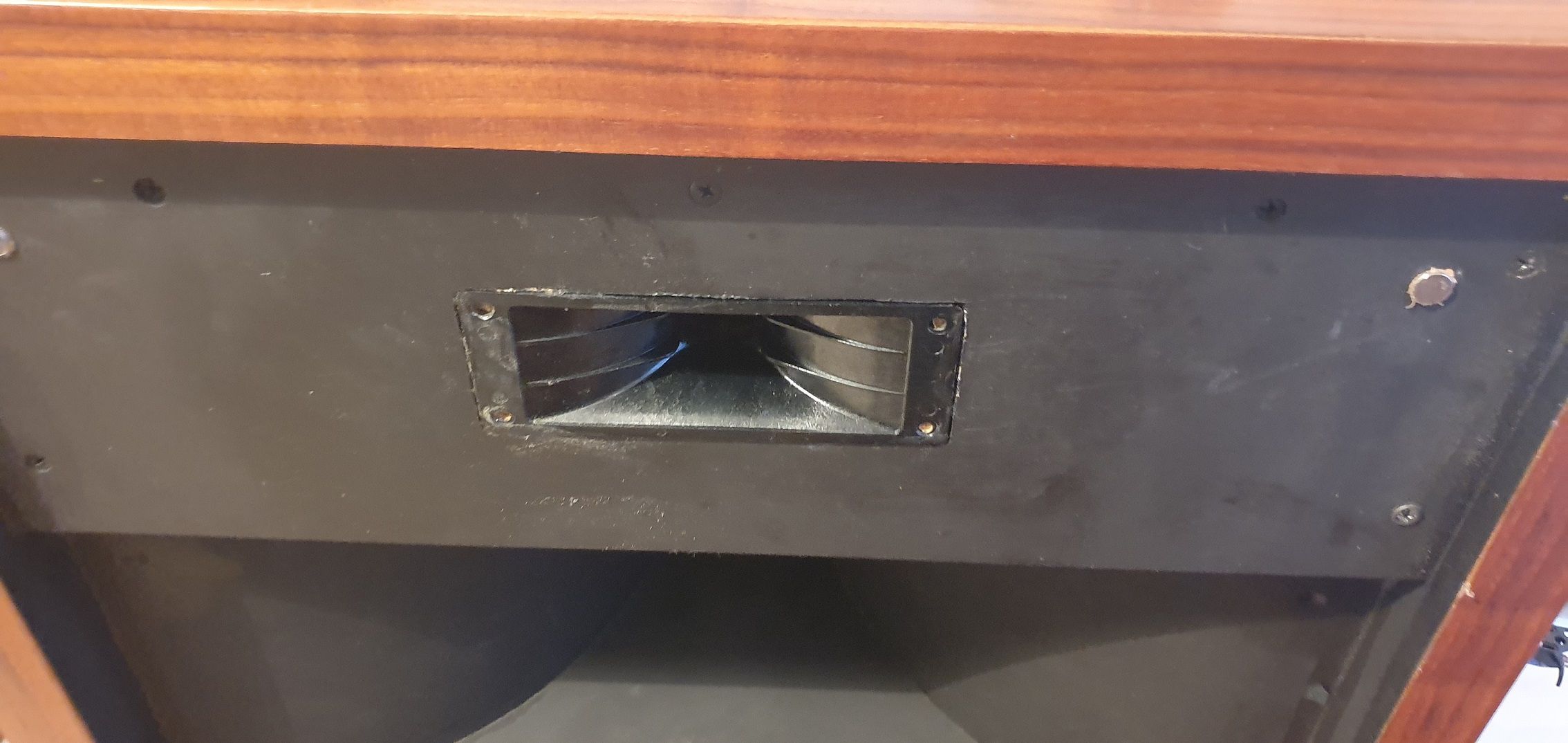
Hey - likely a silly question incoming here. I have a set of Cornscala. I am in the process of making some improvements (bi-amping, new ALK ES5800T high crossover, and replace CT125 with CT120 tweeter). The problem is, whoever made these was a bit of a woodworking genius, and I cannot for the life of me get the tweeter and throat out. Panel is perfectly recessed to match the throat, same throat on CT120. However on both the CT125 in the speaker, and the CT120 I want to put in, the throat seems firmly affixed to the circular driver (threaded with glue). Even the with magnet removed, I cannot get it through the recessed area which is quite thick, frontwards or backwards. Am I an idiot? How do these things get in there?
-
What is Fc? What would recommend with those particular drivers?
-
thanks Chris. Insightful as always.
-
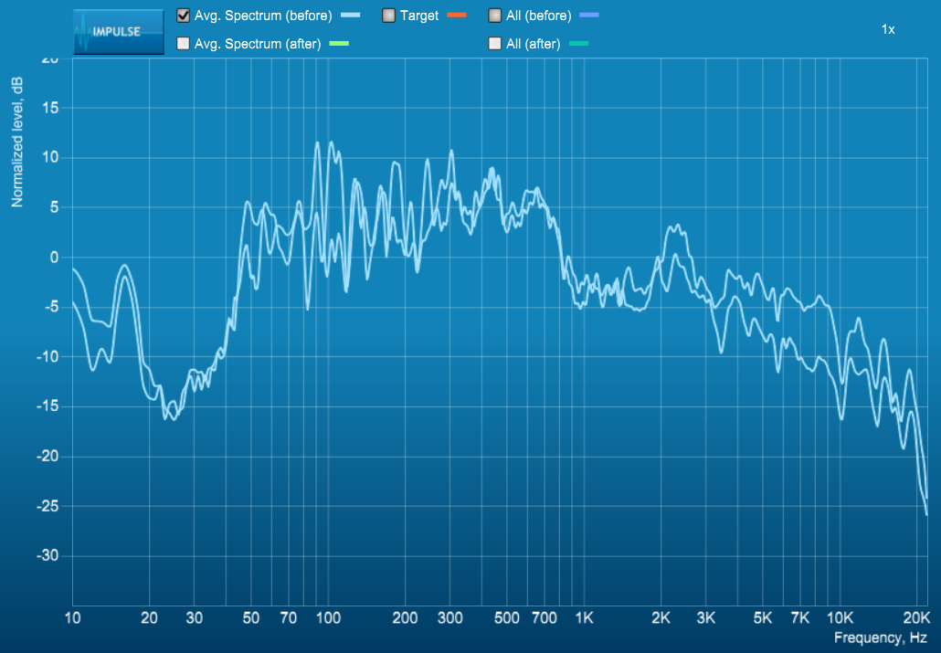
Sorry mate, what do you mean I've decided what the solution is? Do you mean 'I have assumed the solution is to make my speakers perfectly flat out of the box' as the solution. Obviously they will never be flat, but I am interested in exploring how they could be improved (aside from DIRAC) "and that the tweeters appear to have drooping response above 10 kHz." Is this fixable or is this just a hard fact of the tweeter? While I understand tri-amping will allow individual level control and timing control - would that fix the roll-off problem I have with the highs? Or would it just life the droopy response upward? I suppose you could correct that with EQ etc.
-
Thank you Chris. Plenty to think about. For me, it is not necessarily about doing something more... just trying to see if there are any clues as to why it is occurring, which you have helped. I agree the 3 levels are out. The woofer I can correct via the active crossover. The squawker/tweeter I currently only have the active crossover and relative autoformer attentuation. My concern however was that while I could increase the tweeter power (remove autoformer/different tap etc.) it would still not amend the 'droop' you describe - presumably it will lift relatively evenly across the spectrum. Why would the tweeter have such droop? Is that normal for this device? Tri-amping sounds interesting. Presumably this allows great levels of correction (frequency/power/timing). Whilst DIRAC may be frowned upon, what is has done to this system under bi-amping is absolutelu incredible.
-
Ok i will measure. You are correct regarding shape... they are normally shorter and wider. Took a quick measurement: 540 depth 510 width 1050 height Adjusting for around 35mm of panel thickness (these boys are thick and heavy) leaves about .202cubic m or 7.0777777777 cubic feet. Less some volume occupied by horns. So an unconventional shape, but the size seems fine. Note there is no separation in compartment (I have seen some implementations where the bass bin is separate.
-
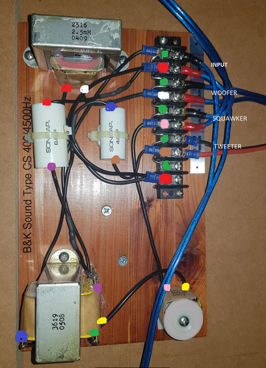
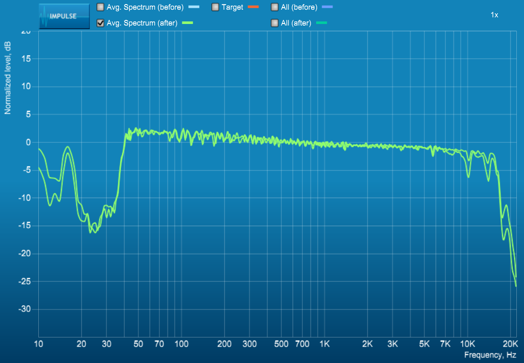
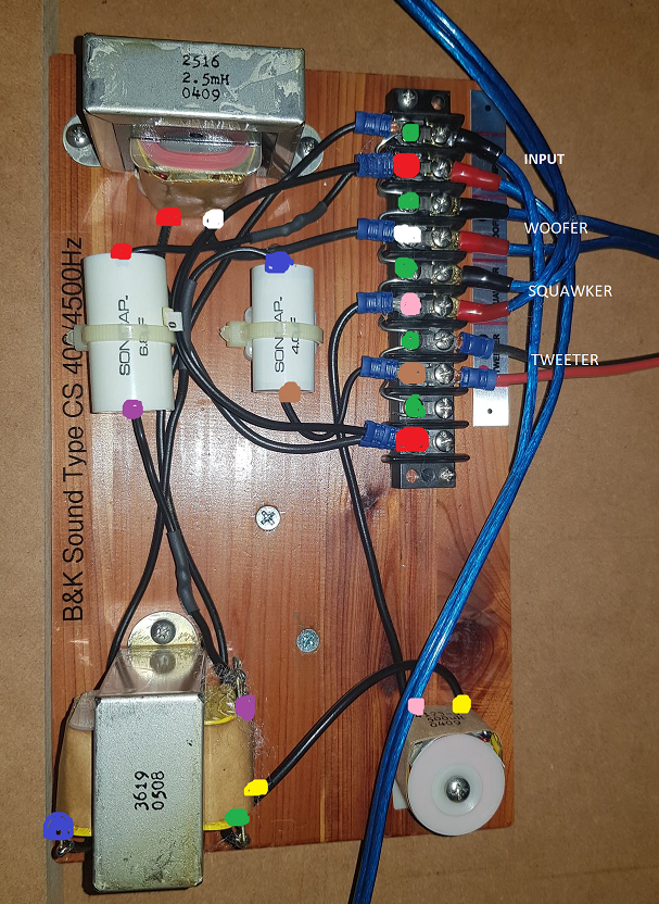
Team, I am seeking some advice here. Some background is avilable here (first struggling with overpowering mids, then bi-amping and active EQ), though I have since moved house and things have moved on: Cliffs notes: - Bought cornscala, found them muddy - very overpowering around 300-400hz, not much down very low, not much up top - Started using Dirac and a MiniDSP 2x4 DDRC to EQ this better, and use a more powerful solid state amp to push the additional boost down low. - System sounds great, good imaging, balanced, quite happy. However, I would like to minimise the amount of correction that DIRAC is required to do. Ideally 0. It is doing an amazing job and I get alot of enjoyment from it, but I would like to understand root cause given this is decent gear. I am trying to understand what could be causing this poor high-end frequency response, and what steps I could take to ascertain it? Since Cornscala is not a real model, this particular build consists of: Midrange Driver is a PD-5VH mated to a wooden horn (see pics) Tweeter is a CT125 Woofer is a CW1526C Crossover is B&K Sound Type CS 400/4500Hz Amps are a 15W Transcendant Son of Beast for the Highs, AMPower SA1 200W Solid State for the woofer. Low amp attentuated in the active corssover to compensate. MiniDSP is providing active crossover at 450Hz. Low is directly wired to amp (crossover bypassed). Existing crossover is maintained and components bypassed to still provide the 4500Hz crossover point between Squawker/Tweeter (details in other post). Speakers themselves sound great when corrected, but I want to understand why the response might be so bad. I do not know who originally built them, but the wood, workmanship, heft, quality, attention is amazing - so I would like to get these to their potential. 1. Could the crossover be busted and maybe look to ALK or similar for a new one? 2. I still have the Squawker/Tweeter coming off the -6db and -3db pins of the autoformer - any issue there (besides wasting some power...but power is not my issue)? 3. Could my crossover modification have created an impedance issue (though this symptom existed even when they were single-amped) Note these problems were the same before I bi-amped. Ideas/Tips/Advice from those far smarter than I. Happy to supply any more info as required. There are pics of the units in the Bi-Amping thread linked. This is the pre-read from DIRAC (9 full spectrum sweeps in various positions, averaged) Below is the response (supposedly) after the filter is applied. Crossover pre-modification/bypass:
-
Well I modified the crossover to remove the top inductor and squawker capacitor, heat shrieked them off and added a new wire to pin 5. Woofers now wired direct. Worked a treat. Used MiniDDP DDRC24 to put in active crossover. Bass driver driven by Solid State with 240W into 4Ohms, so I padded 12dB. Defeinitly far more drive down low. Mids and highs now clearer too. I think at 15W OTL was struggling at high volume. Great success. I have managed to create a 50Hz hum, so will review all my power this weekend. Thanks for the help. This thing really thumps and sings now.
-
Brilliant, thanks mate! Off to the US for 2 weeks, when I return the MiniDSP should be there and I'll test it all out!
-
okay. @mboxler does this sound right based on your feedback? So my understanding of what I would need is: - Remove 2.5mH Inductor from circuit which is acting as low pass for Woofer. Crossover to be implemented in MiniDSP. - Remove 6.8uF capacitor filtering the Input+ before the autoformer. This is acting as High Pass at 400Hz. Crossover to be implemented in MiniDSP. - Feed Input+ to Pin 5 of 3619 Autoformer and out of pin 4 (-3dB), into 500uH inductor to act as low pass to Squaker+ (4500Hz) - Feed Input+ to 4.0uF Cap to act as 4500Hz high pass This would re-arrange the autoformer, which currently has the Squawker on Pin 3 (-6dB) and Tweeter on Pin 4 (-3dB). This is because I would do the first -3dB attenuation in MiniDSP crossover, so only the incremental -3dB to the Squawker is required. Or I could leave it as-is and have the passive crossover/autoformer handle this. Would this woofer removal cause any load issues? I presume the load presented to the upper amp would increase, likely a good thing for the valve amp.
-
DIY skills are okay. I built the amps, so the crossover should be fine. I just need to be sure of the circuit etc.
-
Color coded all the connections if this might help decipher:
-
Yes thanks, they are definitely a mixed bag and not standard. Attached is a clearer picture of the crossover, and some notes (no time to draw full circuit yet): - Single set of inputs (top-most pair) - Second set from top is woofer, with Input + running into the 2.5mH inductor top left, then out to Woofer + - 3rd set from top is Squawker, with + fed by 500uH inductor bottom right, which is fed by Pin 3 of Bottom left Unit - 4th from Top is Tweeter, fed from output of 4.0uF smaller cap, which is fed from Pin 4 on Bottom Left Unit - The botttom left unit is wired as follows: - Pin 4 to 4.0uF cap - Pin 5 to 6.8uF cap, fed by Input + - Pin 0 fed to Input - - Pin 3 to 500uH inductor Let me know thoughts. I believe I can feed the woofer directly, but I am unsure of the load and crossover characteristics presented to the other amplifier once the woofer is removed. Plan was to separe incoming signal: 400Hz Low Pass to woofer, 400Hz High Pass into existing crossover network (pending viability)
-
Team, I am the 3rd owner of a set of Cornscala's here in Australia. Very well built, very solid, very nice. I am considering bi-amping, with my 15W Tube OTL for the Mids/Tops, and a Solid State for the bass driver. This is to get additional headroom to allow me to EQ for my room which I have trialled with good results to accompany my room treatments. Midrange Driver is a PD-5VH (16 Ohm) mated to a wooden horn Tweeter is a CT125 (8Ohms) Woofer is a CW1526C (4 Ohm i believe) Crossover is B&K Sound Type CS 400/4500Hz My plan to achieve this was to use a MiniDSP as an active crossover, set around 400Hz. Couple of questions: How/can I modify the passive-crossover to allow for this? Do I need to? My hope was to feed the woofer directly (active crossover), and still use the passive crossover to handle the Mid/Tweeter crossover. Would this approach (3 way crossover with no load hanging off the Woofer) cause issues? Would the load presented to the Valve amp change? What would need to be done to allow this bi-amping? Any advice would be greatly appreciated.